ActivO SPIN PRO-81.3 User manual


User Manual
All the information is correct at the time of print

IMPORTANT!
Please read all instructions carefully before using this product.
Retain this manual for future reference.
The specifications of this product may vary slightly from the illustrations and are
subject to change without notice.
CONTENT
Safety Instructions 01
Warranty Claim 03
Product Parts 04
Product Installation 08
Exercise Guide 11
Product Operation Guide 13
Trouble Shooting 14
Product Maintenance 14
Product Specification 15
Contact Us 16
Thank you for purchasing the Activo Spin Pro B1.3.
Before operating this unit, please read this manual carefully to
ensure optimum performance and safety.
This manual should be kept available for future reference.

User Manual 1
Safety Instructions
Caution
Read this user manual carefully before use.
Follow the assembly instructions carefully.
It is important to read the entire manual before assembling and using the equipment.
Safe and efficient use can only be achieved if the equipment is assembled, maintained
and used properly. It is your responsibility to ensure that all users of the equipment
are informed of all warnings and precautions.
1.Before starting any exercise program you should consult your doctor to
determine if you have any physical or health conditions that could create a risk to
your health and safety, or prevent you from using the equipment properly. Your
doctor's advice is essential if you are taking medication that affects your heart rate,
blood pressure or cholesterol level.
2.Be aware of your body's signals. Incorrect or excessive exercise can damage
your health. Stop exercising if you experience any of the following symptoms: Pain,
tightness in your chest, irregular heartbeat, extreme shortness of breath, feeling
light headed, dizzy or nauseous. If you do experience any of these conditions you
should consult your doctor before continuing with your exercise program.
3.Keep children and pets away from the equipment. The equipment is designed
for adult use only.
4.Use the equipment on a solid, flat level surface with a protective cover for your
floor or carpet. For safety, the equipment should have at least 0.6 meter of free
space all around it.
5.Before using the equipment, check the nuts and bolts are securely tightened.
Some parts like pedals etc.
6.The safety level of the equipment can only be maintained if it is regularly
examined for damage and/or wear and tear.
User Manual 2
Safety Instructions
7. Always use the equipment as indicated. If you find any defective components
whilst assembling or checking the equipment, or if you hear any unusual noise
coming from the equipment during use, stop. Do not use the equipment until the
problem has been rectified.
8. Wear suitable clothing whilst using the equipment. Avoid wearing loose clothing
which may get caught in the equipment or that may restrict or prevent movement.
Please cycle it slowly in the beginning. Please hold the handlebar tightly and do
not let your body leave the seat when exercise.
9. The equipment has been tested and certified to EN957 under class H.C.
Suitable for domestic, home use only. Maximum weight of user, 100kg. Breaking
is speed independent. Keep clothes, jewelry or loose items away from moving
parts.
10. The equipment is not suitable for therapeutic use.
11. Care must be taken when lifting or moving the equipment so as not to injure
your back. Always use proper lifting techniques and/or use assistance.
Please note:
Maximum weight capacity for the Activo Spin Pro B1.3 is 100 kg.
WARNING
WARNING
BEFORE BEGINNING ANY EXERCISE PROGRAM CONSULT YOUR
PHYSICIAN. THIS IS ESPECIALLY IMPORTANT FOR INDIVIDUALS WITH
PRE-EXISTING HEALTH PROBLEMS. READ ALL INSTRUCTIONS BEFORE
USING THIS FITNESS EQUIPMENT. WE ASSUME NO RESPONSIBILITY FOR
PERSONAL INJURY OR PROPERTY DAMAGE SUSTAINED BY OR
THROUGH THE USE OF THIS PRODUCT.
This marking indicates that this product should not be disposed with other
household wastes throughout the EU. To prevent possible harm to the
environment or human health from uncontrolled waste disposal, recycle it
responsibly to promote the sustainable reuse of material resources.
Caution: Read this user manual carefully before use.

User Manual 3
Warranty Claim
1.Warranty is not transferable.
2.This warranty is effective only if the product is purchased from ACTIVO or its
authorized dealers.
3.Proof of purchase (original receipt) is required for all warranty repairs.
4. AII implied warranties, including but not limited to these implied warranties of
fitness and merchantability, are limited to one (1) year from the date of purchase.
5.Damage due to misuse, improper treatment and unauthorized modification
and repairs are not covered by this warranty.
6.Warranty does not cover accessories and add-ons, which do not belong to this
product.
7. Warranty is not effective to rental, business, commercial, institutional, or other
non-residential users.
8.
AII services covered by this warranty must be approved by ACTIVO and
repaired by authorized technicians only.
9.
lf replacement parts for defective materials are not available, ACTIVO
reserves the right to make substitutions in lieu of repair or replacement.
User Manual 4
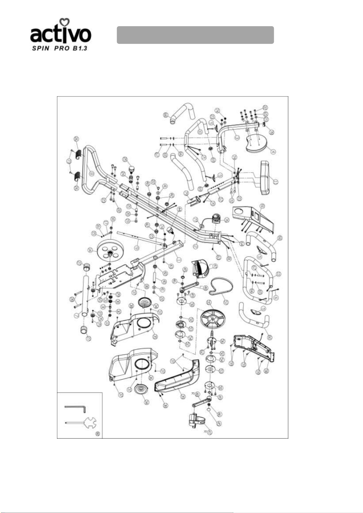
Product Parts
Before you begin assembly, please take a moment to review the Hardware and
Parts List on the following pages. Each part has been illustrated and numbered for
easy identification.

User Manual 5
Product Parts
ASSEMBLY TOOLS AND NECESSARY PARTS
1. #82 Spanner
2. #82 Hex wrench
×4sets
1. #22 Hex head Allen screw M18×1.25×16L
2. #23 Flat washer Φ8.2×Φ20×1.5
1. #22 Hex head Allen screw M8×1.25×16L
2. #65 Spring washer M8
3. #23 Flat washer Φ8.2×Φ20×1.5
1. #28 Square neck bolts M8×1.25×50L
2. #51 Dome nut M8×1.25
3. #65 Spring washer M8
×4sets
×2sets
×1pc
×1pc
User Manual 6
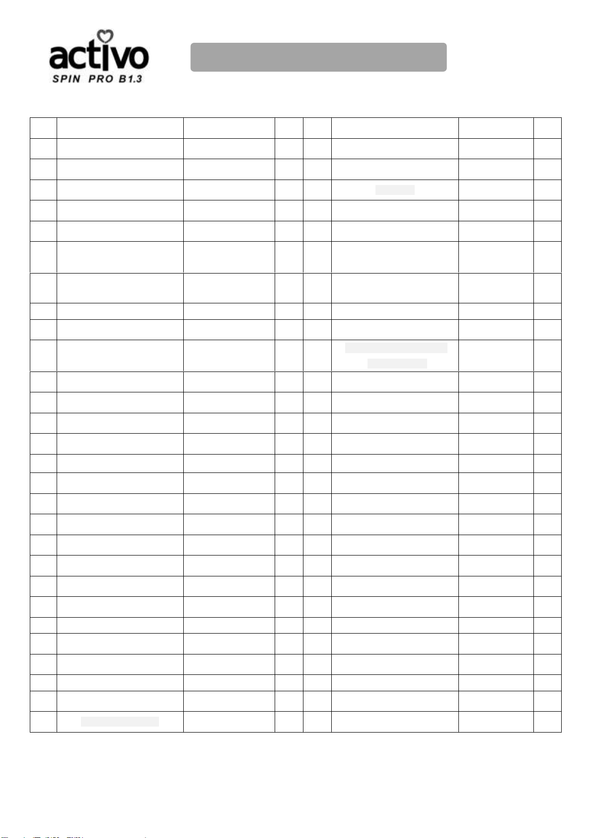
Product Parts
NO
NAME
Specification
Qty.
NO.
NAME
Specification
Qty.
1
Main frame (1)
1
29
circlip
Φ10
1
2
Main frame (2)
1
30
bearing
6000RS
2
3
Back rest support tube
1
31
Idler shaft
1
4
Back rest
1
32
Flat washer
Φ10.2×Φ25×1.5
1
5
Pulse sensor
4
33
Nylon nut
M10×1.5
1
6
Front handle bar pulse
sensor wire
2
34
Small cover
2
7
Front stabilizer
1
35
Left cover
1
8
Rear stabilizer
1
36
Right cover
1
9
Support& adjusting tube
1
37
Cross recess head screw
M4×0.7×10L
9
10
Rear handle bar
1
38
cross recessed pan head
tapping screw
ST4.2×16L
4
11
saddle
1
39
Front cover
1
12
Saddle support post
1
40
Axle of rotation
1
13
Front Handle bar
1
41
Flat washer
Φ8.2×Φ26×1.5
2
14
flywheel
1
42
Bushing
6
15
Nylon nut
M6×1.0
4
43
Flat head Allen screw
M8×1.25×35
3
16
Flat washer
Φ6.1×Φ12×1.5
2
44
Adjusting knob
M16×1.5×30L
1
17
bolt
M6×1.0×40L
2
45
Crank cover
2
18
Hex nut
M10×1.0
2
46
Flange nut
M10×1.25
2
19
Hex head Allen screw
M10×1.5×40L
2
47L
Left Pedal
JD-16A
1
20
Flat washer
Φ10.2×Φ20×1.5
2
47R
Right Pedal
JD-16A
1
21
Rotating casing
Φ10.2×Φ14×28L
2
48L
Left Crank
1/2×127L
1
22
Hex head Allen screw
M8×1.25×16L
10
48R
Right Crank
1/2×127L
1
23
Flat washer
Φ8.2×Φ20×1.5
14
49
Cross recess head screw
M6×1.0×14 L
6
24
Adjusting support bracket
1
50
Bearing inner seat plate
2
25
Adjusting knob
M16×1.5×20L
1
51
Dome nut
M8×1.25
2
26
Plastic pad
2
52
circlip
Φ17
4
27
Adjusting foot tube end
2
53
Bearing bush seat
2
28
Square neck bolts
M8×1.25×50L
2
54
Bearing outer seat plate
T=1.2
2

User Manual 7
Product Parts
NO.
NAME
Specification
Qty.
NO.
NAME
Specification
Qty.
55
Belt pulley
1
69
Round tube end plug
Φ25
2
56
Pulley axle
Φ17
1
70
Rear handle bar pulse
sensor wire(middle)
2
57
belt
1
71
Rear handle bar pulse
sensor wire(top)
2
58
Console bottom cover
1
72
Square neck bolts
M8×1.25×45
L20
2
59
Round head cross
screws
M5×0.8×10 L
6
73
Flat taper cross tapping
screw
ST4.2×16L
2
60
Front handle bar foam
2
74
Nylon nut
M8×1.25
6
61
Console top cover
1
75
Round head cross screw
M6×1.0
2
62
cross recessed
countersunk head screw
M6×1.0×14L
4
76
Transportation wheel
2
63
cross recessed
countersunk head screw
M5×0.8×10 L
1
77
elliptical protective plug
1
64
Rear handle bar pulse
sensor wire(bottom)
2
78
elliptical tube end plug
1
65
Spring washer
M8
8
79
bushing
1
66
Curved washer
Φ8.2×Φ20×1.5×R13
6
80
Speed sensor
wire(bottom)
1
67
Hex head Allen screw
M8×1.25×40 L25
4
81
Speed sensor wire(top)
1
68
Rear handle bar foam
2
82
tools
2

User Manual 8
Product Installation
Step 1:
--Pull out the Adjusting knob (25) on the Supporting &
adjusting tube (9) while opening the bike's main frame, then
select a proper hole and fix in . (Note: you can adjust
the height accordingly if necessary.)
--Unscrew the dome nut (51)by Spanner (82), remove the
metal tube, but must keep the dome nut(51), spring
washer(65) and square neck bolt (28).
Step 2:
--Attach the front Stabilizer(7)to the Main frame (1),
Tighten it with the dome nut(51) , spring washer(65)
and square neck bolt (28)by spanner(82).
--Then fix the rear stabilizer ( 8 ) to the main frame ( 2 )
properly with hex head allen screw (22) and Flat washer
(23) by hex wrench
Step 3:
--Fix the pedal(47L) which is marked "L" on the
crank(48L) marked "L" with spanner tightly by
anticlockwise, then fix the pedal (47R) which is
marked "R" on the crank(48R) marked "R" with
spanner tightly by clockwise.
If you find it not leveled on the floor, you can adjust it
by the adjusting foot tube end (27).

User Manual 9
Product Installation
Step 5:
--Loosen the spring washer (65), Curved washer (66)
and Hex head Allen screw (67) by hex wrench.
Fix the Front Handle bar (13) with spring washer (65),
Curved washer (66) and Hex head allen screw (67)
by hex wrench.
Step 6 :
--Attach the Console top cover (61) to the Front Handle bar (13)
first , then match the Console bottom cover (58) to the console
top cover (61) after connected all the wires properly. tighten the
whole console with Round head cross screw (59) by spanner.
(Note: the wires must be connected correctly by the
remarks on the wires, such as L1-L1, R1-R1, etc. Please
double check to make sure the equipments has been
assembled properly before use it . )
Step 4:
--Screw down the Flat washer (23) and Nylon nut (74)
on the saddle (11) by the spanner. Then fix the saddle (11)
to the saddle support post (12) with Flat washer (23) and
Nylon nut (74) by the spanner.
--Connect all the wires properly first, then loosen the
adjusting knob (44)and pull it out first before sliding the
saddle support post (12) into the saddle support post
housing on the Main Frame (1), and align holes for your
desired height, then release the adjusting knob and tighten
it properly.(Note : the wires must be connected correctly
by the remarks on the wires, according to L2-L2, R2-R2 )
--Fix the back rest (4) to the Back rest support tube (3) with hex head allen screw (22), Spring washer(65) and Flat
washer (23) by hex wrench. Then attach the Back rest support tube (3) to the Saddle support post (12) with
square neck bolts (72), nylon nut (74) and flat washer (23) by hex wrench
--Fix the rear handle bar (10) to the Back rest support tube (3) with spring washer (65), Curved washer (66) and
Hex head allen screw (67) by hex wrench, then connect all the wires properly. (Note : the wires must be
connected correctly by the remarks on the wires, according to L2-L2, R2-R2 )

User Manual 10
Product Installation
Caution:
This bike
is
foldable. You can fold
it
up and put aside.
NOTE: Do watch your hand while unfolding and folding the bike.
User Manual 11
Exercise Guide
Using your EXERCISE BIKE will provide you with several benefits,
it
will
improve your physical fitness, tone muscle and in conjunction with calorie
controlled diet help you lose weight.
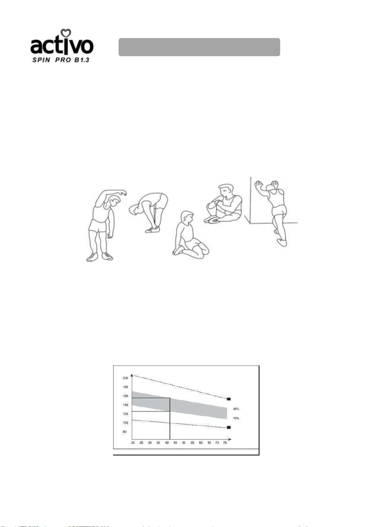
1. The Warm Up Phase
This stage helps get the blood flowing around the body and the muscles working properly.
It
will also reduce the risk of cramp and muscle injury.
It
is advisable to do a few stretching
exercises as shown below. Each stretch should be held for approximately 30 seconds, do
not force or jerk your muscles into a stretch -
ifit
hurts, STOP.
2. The Exercise Phase
This isthe stage where you put the effort in.After regular use
,
the muscles in your legs
will become more flexible. Work to your own pace but it is very important to maintain a
steady tempo throughout. The rate of work should be sufficient to raise yourheartbeat
intothetargetzoneshownonthegraphbelow.
This stage should last for a minimum of 12 minutes though most people start at about 15-20minutes

User Manual 12
Exercise Guide
3.
The Cool Down Phase
This stage isto letyourCardio-vascular System and muscleswinddown.This isa repeat
ofthewarmupexercisee.g.reduceyourtempo,continueforapproximately5
minutes.The
stretching exercises should now be repeated, again remembering not to
force orjerk your
muscles intothe stretch. As you get fitter you may need to train longer and harder.
It
is
advisable to train at least three times aweek, and if possible
space your workouts evenly
throughout theweek.
4. Fault Finder
If you do not receive numbers appearingonyour computer,please ensure all
connections arecorrect.
Muscle Toning
To tone muscle while on your EXERCISE BIKEyou will need to have the resistance set quite
high. This will put more strain on your leg muscles and may mean you cannot train for as
long as you would like. If you are also trying to improve your fitness you need to alter your
training program. You should train as normal during the warm up and cool down phases,
buttowards the end of the exercise phase you should increase resistance making your legs
work harder.You will have to reduce your speed to keep your heart rate inthetarget zone.
Weight Loss
The important factor here
is
the amount of effort you put in.The harder and longer you work
the more caloriesyou will burn. Effectively this
is
the same as ifyouwere training to improve
your fitness, the difference
is
the goal.
Use
The seat height can be adjusted by removing the adjustment knob and ra1smg or lowering
the seat. There are 7 holes in the seat post allowing for a range of heights. Once the correct
height has been chosen, refit the adjustment knob and tighten. The tension control knob
allows you to alter the resistance of the pedals.A high resistance makes it more difficult to
pedal, a low resistance makes it easier. For the best results set the tension while the bike
is
in
use.

User Manual 13
Product Operation Guide
CONSOLE INSTRUCTION
SPECIFICATIONS:
TIME …………………………………………………………………………00:00-99:59
SPEED(SPD)…………………………………………………………0-99.9KM/H(ML/H)
DISTANCE(DIST)…………………………………………………………0-999.9KM(ML)
CALORIE(CAL)………………………………………………………………0-9999KCAL
ODOMETER(ODO)………………………………………………………0-999.9KM(ML)
PULSE(PUL)........................................................................................40-240BPM
KEYFUNCTIONS:
MODE(SELECT/RESET):This key lets you to select and lock on to a particular function you want.
SET(IF HAVE):Can to proceed the data establish for “TIME” “DISTANCE” “CALORIES”.
CLEAR(RESET):The key to reset the value to zero by pressing the key.
OPERATION PROCEDURES:
1. AUTO ON/OFF
The system turns on when any key is pressed or when it sensor an input from the speed sensor.
The system turns off automatically when the speed has no signal input or on key are pressed for
approximately 4 minutes.
2. RESET
The unit can be reset by either changing battery or pressing the MODE key for 3 seconds.
3. MODE
To choose the SCAN or LOCK if you do not want the scan mode, press the MODE key when the
pointer on the function you want which begins blinking.
FUNCTIONS:
1. TIME: Press the MODE key until pointer lock on to TIME. The total working me will be shown
when starting exercise.
2. SPEED: Press the MODE key until the pointer advanced to SPEED. The current speed will be
shown.
3. DISTANCE: Press the MODE key until the pointer advanced to DISTANCE. The distance of each
workout will be displayed.
4. CALORIE: Press the MODE key until pointer lock on to CALORIE. The calorie burned will be
displayed when displayed will be shown.
5. ODOMETER (IF HAVE): Press the MODE key until the pointer advanced to ODEMETER. The
total accumulated distance will be shown.
6.PULSE(IF HAVE):Press the MODE key until the pointer advance to PULSE, User’s current heart
rate will be displayed in beats per minute. Place the palms of your hands on both of the contact
parts(or put ear-clip to ear), and wait for 30 seconds for the most accurate reading.
SCAN: Automatically display changes every 4 seconds.
BATTERY:
If improper display on monitor, please reinstall the batteries to have a good result.

User Manual 14
Trouble Shooting
PRODUCT MAINTENANCE
1.
When you don't use the exercise bike for a long time, please take out the
computer battery to avoid running out of battery.
2.Often clean the exercise bike with clean cloth to keep the clean appearance.
3.
Please payattentiontothe connection parts, screws, nuts looseor not,
frayed or not, broken or not.And often wipe the oil to improve the flexibility of
bike.
4.
Please set up bike
in
a dry level place and keep
it
away from moisture and water.
When you finished exercise, please don't forget to wipethe sweat from biketo
avoid
theappearancerusting.
Trouble
Reasons
Solution
Remark
Without sensor
Sensor wire didn't
connected well or broken
re-connected th sensor
wire or replace with new
sensor wire
Computer
without display
Computer battery runs
outor batterynegative
andpositive in reverse
Replace new battery or
check the battery negative
and positive side correct
or not
Noisy
Movingpartsislooseor
lack of lubricatingoil
Tightentheloosepartsor
wipelubricatingoil

User Manual 15
Product Specification
Product name
ACTIVO Spin Pro B1.3
Model
AC3200
Packing dimension (cm)
116L x 40W x 22H
Product dimension (cm)
108.5L x 51W x 100.5H
Net weight
21kg
Gross weight
23.5kg
Max load
100kg
Colour
Grey
Material
Steel, ABS, PP

User Manual 16
Contact Us
MALAYSIA
Healthy World Lifestyle Sdn Bhd
No. 22 Jalan Anggerik Mokara 31/47
Kota Kemuning, 40460 Shah Alam
Selangor Darul Ehsan, Malaysia.
Tel: +603-5121 4286
Fax: +603-5121 4386

目录
安全说明 01
保修说明 03
产品配件 04
产品安装 08
训练指导 12
产品使用说明 13
疑难解答 14
产品保养 14
产品规格 15
联系我们 16
ACTIVO 真心感谢您选择 Spin Pro B l.3,使用前请阅读此说明书,
特别是安全说明部分。并保留此说明书予以备用。
备注:
本公司将保留修改设计和产品最终解释权。
产品颜色以实物为准。
Table of contents
Popular Fitness Equipment manuals by other brands


G-FITNESS
G-FITNESS AIR ROWER user manual

CAPITAL SPORTS
CAPITAL SPORTS Dominate Edition 10028796 manual

Martin System
Martin System TT4FK user guide

CIRCLE FITNESS
CIRCLE FITNESS E7 owner's manual

G-FITNESS
G-FITNESS TZ-6017 user manual

Accelerated Care Plus
Accelerated Care Plus OMNISTIM FX2 CYCLE/WALK user manual


