G-FITNESS AIR ROWER User manual

AIR ROWER
USER MANUAL
IMPORTANT !
Please read all instructions carefully before using this product.
Retain this manual for future reference.
The specifications of this product may vary slightly from the
illustrations and are subject to change without notice.

2
TABLE OF CONTENTS
SAFETY INSTRUCTIONS
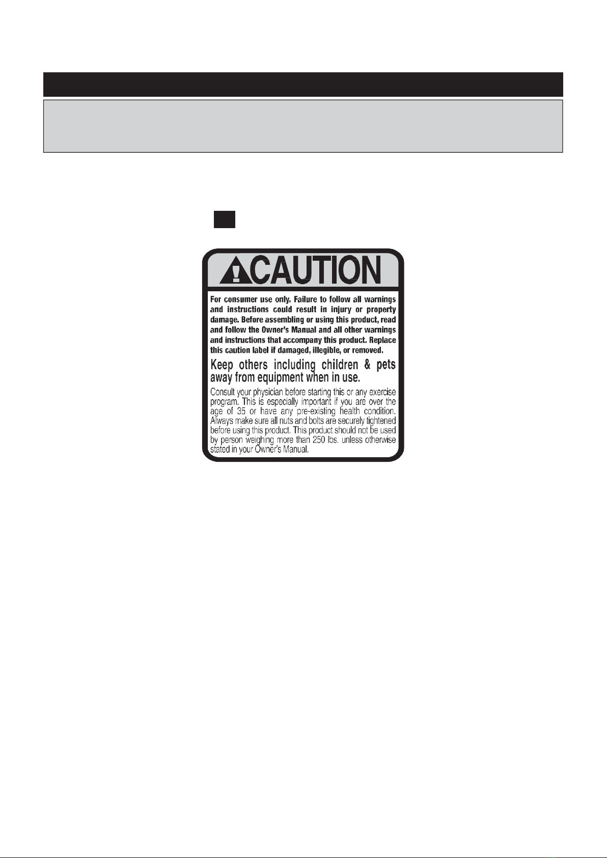
!WARNING Cancer and Reproductive Harm www.P65Warnings.ca.gov
!WARNING
!WARNING
Consult your physician before starting this or any exercise program. This is
especially important if you are over the age of 35, have never exercised before,
only. Do not use in institutional or commercial applications. Failure to follow all
warnings and instructions could result in serious injury or death.
To reduce the risk of serious injury, read the following Safety Instructions
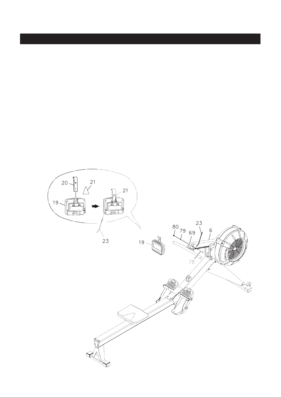
before using the FAN ROWER.
1.
Save these instructions and ensure that other exercisers read this manual prior to using the
FAN
ROWER
2.
Read all warnings and cautions posted on the
FAN ROWER.
3.
The
FAN ROWER
should only be used after a thorough review of the Owner’s Manual. Make
sure that it is properly assembled and tightened before use.
4.
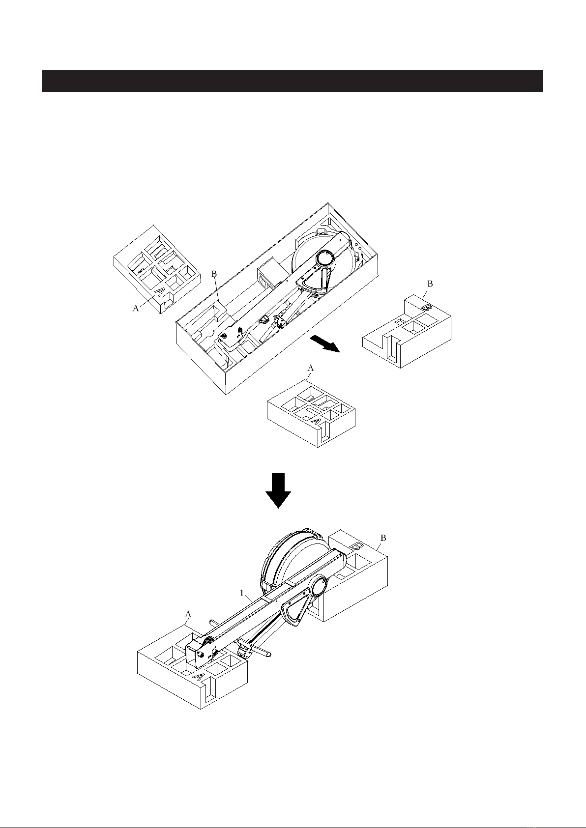
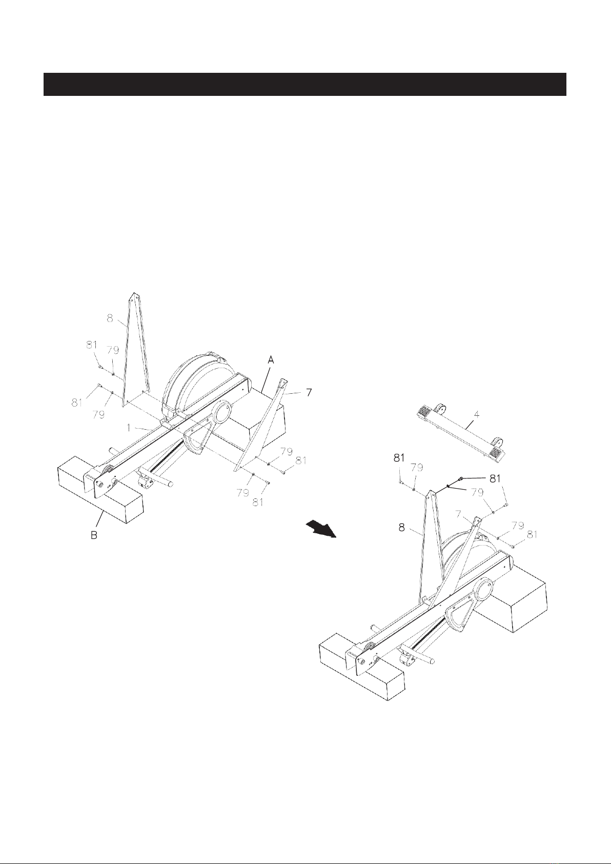
We recommend that two people be available for assembly of this product.
5.
Keep children away from the
FAN ROWER.
Do not allow children to use or play on the
FAN ROWER.
Keep children and pets away from the
FAN ROWER
when it is in use.
6.
It is recommended that you place this exercise equipment on an equipment mat.
7.
Set up and operate the
FAN ROWER
on a solid level surface. Do not position the
FAN ROWER
on loose rugs or uneven surfaces.
8.
Make sure that adequate space is available for access to and around the
FAN ROWER.
9.
Before using, inspect the
FAN ROWER
for worn or loose components, and securely tighten or
replace any worn or loose components prior to use.
10.
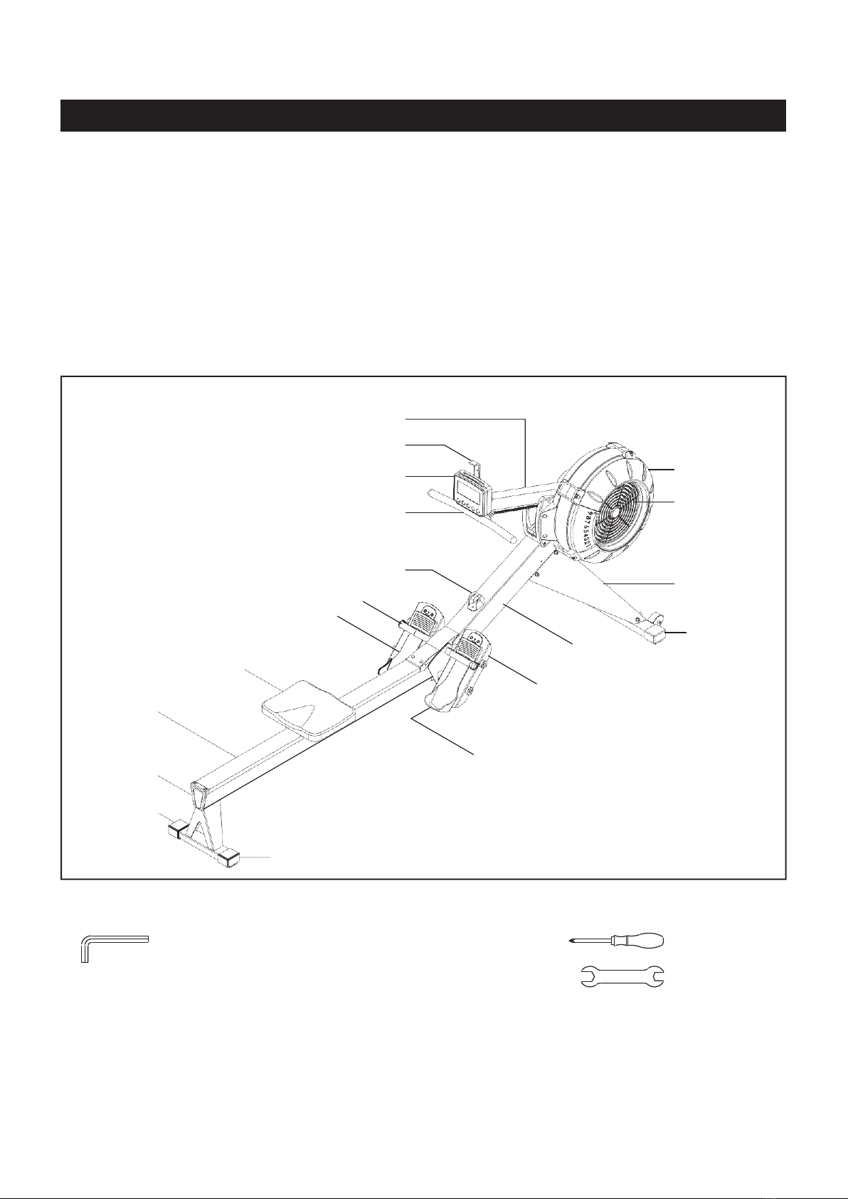
Before using, check the condition of the CHAIN(36). Replace the CHAIN(36) if it is cracked or broken.
11.
Consult a physician prior to commencing an exercise program and follow his/her recommendations in developing
physician.
12.
Always
within them. Always use common sense when exercising.
13.
Do not wear loose or dangling clothing while using the
FAN ROWER.
14.
Never exercise in bare feet or socks; always wear proper footwear such as running, walking, or cross training
15.
Be careful to maintain your balance while using, mounting, dismounting, or assembling the
FAN
ROWER,
loss of balance may result in a fall and bodily injury.
16.
Do not use the SEAT(51) to move the
FAN ROWER .
The SEAT(51) will move and the SEAT and
make sure your hands are clear of any pinch point.
17.
The
FAN ROWER
should not be used by persons weighing over 300 pounds.
18.
The
FAN ROWER
should be used by only one person at a time.
19.
The
FAN ROWER
is for consumer use only. It is not for use in public or semipublic facilities.

3
BEFORE YOU BEGIN
Thank you for choosing the FAN ROWER . We take great pride in producing this quality product
and hope it will provide many hours of quality exercise to make you feel better, look better, and enjoy
life to its fullest.
It's a proven fact that a regular exercise program can improve your physical and mental health.
Too often, our busy lifestyles limit our time and opportunity to exercise. The FAN ROWER provides
a convenient and simple method to begin your journey of getting your body in shape and achieving a
happier and healthier lifestyle.
B efore reading further, plea s e review th e drawing below and familiarize yourself with the
parts that are labeled.
Read this manual carefully before using the
FAN ROWER .
Computer Post
Cell Phone Bracket
Computer
Handlebar
Right
Fan Cage
Damper
Rail Frame
Seat
Handlebar Holder
Pedal Strap
Pedal Cap
Main Frame
Pedal Support
Right
Support Leg
Endcap
Rail Cap
Pedal Cap
Endcap
Endcap
THE FOLLOWING TOOLS ARE INCLUDED FOR ASSEMBLY :
Allen Wrench (6mm) Screwdriver
Allen Wrench (5mm)
Wrench

4
EQUIPMENT WARNING, CAUTION & NOTICE LABELS
This chart is provided to help identify the warning, caution, and notice labels on the FAN
ROWER. Please take a moment to familiarize yourself with all of the warning, caution, and notice
labels.
Label is larger than actual size
C1 CAUTION LABEL(115)

5
HARDWARE IDENTIFICATION CHART
This chart is provided to help identify the fasteners used in the assembly process. Place the washers or
the ends of the bolts or screws on the circles to check for the correct diameter. Use the small scale to
check the length of the bolts and screws.
3/16" 1/4" 5/16" 3/8" 1/2"
INCHES
0 1/2 1 1/2 2 1/2 3 1/2 4 1/2 5 1/2 6
in.
0 10 20 30 40 50 60 70 80 90 100 110 120 130 140 150
mm.
MILLIMETERS
length
6 8 10 12
NOTICE: The length of all bolts and screws, except those with flat
heads, is measured from below the head to the end of the bolt
or screw. Flat head bolts and screws are measured from the
top of the head to the end of the bolt or screw.
length
After unpacking the unit, open the hardware bag and make sure that you have all the following
fasteners. Some fasteners may be already attached to the parts.
Part Number and Description Qty
72 Philips Head Screw,M6x10mm 2
78 Butto 78 Button Head Cap Screw, M8x75mm 1
79 Flat Washer,M8 1
76 Flat Washer, M6 8
80 NylonLock Nut, M8 1
81 Socket Head Cap Screw, M6x16mm 8
84 Socket Head Cap Screw, M8x160mm 4
9 9 Foot Pedal End Cap 4
98 Pull Pin 1

6
ASSEMBLY INSTRUCTIONS
STEP 1
Take out the packing materials Styrofoam (A) , Styrofam (B). Take the main frame(1) out and put it on
the Styrofoam(A) and Styrofoam(B).The chain cover should be place in the groove of Styrofoam(B).
(Please note the the product can not be placed directly on the ground ,otherwise the chain cover will be
easily crushed or scratched.)

7
ASSEMBLY INSTRUCTIONS
STEP 2
Refer to illustration 1. Turn the main assembly of the FAN ROWER upside down and place
it in the packing material styrofoam(A) and (B) to avoid breaking the chain covers. Attach the LEFT and
RIGHT SUPPORT LEGS(7, 8) to the MAIN FRAME(1) with SOCKET HEAD BOLTS(M8x1.25x12mm)
(81) and WASHERS(M8)(79). Do not tighten all bolts until Step 2.
STEP 3
Refer to illustration 2. Attach the FRONT STABILIZER(4) to the LEFT and RIGHT SUPPORT LEGS
(7, 8) with SOCKET HEAD BOLTS(M8x1.25x12mm)(81) and WASHERS(M8)(79). Then tighten all bolts.
Turn the assembly over.
NOTE: Do not fully tighten bolts until instructed.
1.
2.

8
ASSEMBLY INSTRUCTIONS
STEP 4
Refer to illustration 3. Lift up the MAIN FRAME(1) and RAIL FRAME(2) to insert the RAIL FRAME(2) into
the MAIN FRAME(1). Make the SHAFT(24) on the MAIN FRAME(1) fit into the gap in the RAIL FRAME(2).
Then put the MAIN FRAME(1) and RAIL FRAME(2) down. Refer to illustration 4. Lock the MAIN FRAME(1)
and RAIL FRAME(2) together with the PULL PIN(98).
STEP 5
Refer to illustration 4. Swing up the COMPUTER POST(6), and attach it to the LEFT and RIGHT COVERS
(57, 58) with ROUND HEAD BOLTS(M6x1x10mm)(72).
3.
4.

9
ASSEMBLY INSTRUCTIONS
STEP 6
There is an “L” decal on the left PEDAL CAP(45L), and an “R” decal on the right PEDAL CAP(45R).
Attach the right PEDAL CAP ASSEMBLY(45R) to the right side of the MAIN FRAME(1) with SOCKET
HEAD BOLTS(M8x1.25x160mm)(84) and SECURING CAPS(9). Repeat on other side.
L
R

10
ASSEMBLY INSTRUCTIONS
STEP 7
Refer to the detail view. Insert the CELL PHONE BRACKET(20) into the slot in the COMPUTER(19). Hang
the RUBBER BAND(21) onto the CELL PHONE BRACKET(20) and the COMPUTER(19) as shown.
STEP 8
Install two size C batteries into the COMPUTER(19), the batteries are not included. See page 18 for
detailed battery installation instructions. Attach the COMPUTER(19) to the COMPUTER POST(6) with
BUTTON HEAD BOLT(M8x1.25x75mm)(78), WASHER(M8)(79), and NYLOCK NUT(M8x1.25)(80). Plug
the SENSOR WIRE(23) into the back of the COMPUTER(19).

MAINTENANCE
BUNGEE CORD ADJUSTMENT
Over time, about 250,000 strokes on HANDLEBAR(3),
your BUNGEE CORD(38) may stretch. Follow the
following process to adjust:
1.
Position the MAIN FRAME ASSEMBLY(1) as
shown in the illustration. Remove the MAIN FRAME
CAP(68) from the MAIN FRAME(1). Slid out the
BOTTOM COVER(70) from the MAIN FRAME(1).
2.
Position the MAIN FRAME ASSEMBLY(1) as shown in the below illustration. Unhook the LEFT
BUNGEE CORD HOOK(12L) from the MAIN FRAME(1). Make a mark on the BUNGEE CORD(38)
to move the hook forward 2 inches. Refer to View 1 to View 3 to untie the BUNGEE CORD(38) from
the LEFT BUNGEE CORD HOOK(12L), and move the hook forward 2 inches. Refer to View 4 to
View 6 to retie the BUNGEE CORD(38) to the LEFT BUNGEE CORD HOOK(12L). Hook the LEFT
BUNGEE CORD HOOK(12L) back into the MAIN FRAME(1) and push the hook to the left side to
touch the inner wall of the MAIN FRAME(1). CAUTION: Always use two hands with a secure grip
when re-attaching the BUNGEE CORD HOOKS(12L & 12R).
Unhook the RIGHT BUNGEE CORD HOOK(12R) from the MAIN FRAME(1). Do the same as above
to adjust the BUNGEE CORD(38) on the right side.
1. 2. 3.
4. 5. 6.
3.
Position the MAIN FRAME ASSEMBLY(1) as shown
in the illustration. Slid the BOTTOM COVER(70)
back into the MAIN FRAME(1).Press the MAIN
FRAME CAP(68) into the MAIN FRAME(1).
11

COMPUTERINSTRUCTIONS
12
COMPUTER INSTRUCTIONS
Your FAN ROWER utilizes an air fan system to create resistance for your workout. We
recommend that you use this computer console to vary your workout from session to session and
note your important
source of motivation and interest which will help keep you on track. Meter Function
I. INITIAL SETUP
POWER ON:
- Move the handlebar to start exercising in Quick start program or press any button to go into IDEL mode.
POWER OFF:
-In IDLE mode, automatically shuts off after 20 seconds of inactivity.
-When running an Interval Program, automatically shuts off after 2 minutes of inactivity
-In all other programs, automatically shuts off after 30 seconds of inactivity.
METRIC & STANDARD UNIT:
-The initial factory setting is in “KM”. To toggle between Miles and Kilometers, press and hold “UP” and
DOWN” buttons when console in IDLE mode, it will display flashing “KM”&“MILE”. Press “UP” or
“DOWN” arrows to select “KM” or “MILE” and then press “ENTER” to confirm.
BATTERY INSTALLATION:
-Console operates on 2 Size C batteries. The battery compartment is on the back of the console.
Battery is included.
-When there’s no batteries installed, console can still work in Quick start program.
-

COMPUTERINSTRUCTIONS
13
COMPUTER INSTRUCTIONS
II.FUNCTION BUTTONS
SELECT BUTTON:
-In IDLE mode, press and release SELECT to cycle through each program option. Stopon the program of
your choosing. You can preset target values for DISTANCE, TIME, andCALORIES, GAME, or select an
Interval Program of 20/10, 10/20, or 10/10.
NOTE: Default exercising mode is Quick start program.
(UP BUTTON):
-Press to increase the preset values. Press the button and hold it down, the presetting valuewill go
faster, release the button to stop.
-
(DOWN BUTTON):
-Press to decrease the preset values. Press the button and hold it down, the presetting valuewill go
faster, release the button to stop.
BACK BUTTON:
-When selecting the programs, press the button to return to the previous program.
-When you finish a running program, press the button to jump into the IDEL mode.
ENTER/STOP BUTTON:
-When selecting the programs and presetting target values, press the button to confirm.
-Press the button and hold it down for three seconds to reset all functions to zero and restart the
computer.
-During exercise, when back light is turned off, the first pressing of this button will turn on the back light.
When the back light is still lit, press the button a second time to pause the counting of all function
values. Press the button a third time to restart the workout and continue of the counting of all function
values.

COMPUTERINSTRUCTIONS
14
COMPUTER INSTRUCTIONS
III. CONSOLE DISPLAY
STROKE RATE:
-Display the current stroke per minute during exercise.
-The lightened up semi-circle equals to the stroke rate that displayed in numbers. The more grids it
shows, the higher your stroke rate is.
PULSE:
-Display the heart rate from 40 to 220 beats per minute during exercise. To use this function, the user
must wear Heart Rate Chest Strap.
TIME & TIME/500m AVG:
-Display range: 00:00 ~ 99:59 minutes.
-The workout time is accumulated when under any workout mode.
-Display flashing “00:00” for presetting the TIME (countdown) program. Time can be set from 1:00 to
99:00 minutes.
-Time cannot be saved under10/10 INTERVAL program. Setting range is 10 ~ 99.
-The time/500m is the average time per hour for reaching distance of 500 meters.
WATTS:
-Display range: 0 ~ 999 watts.
-Display the amount of power generated at any moment during the workout.
DISTANCE& DIST/30MIN:
-Display range: 0 ~ 9999 meters. It’s accumulated in cycle mode that numbers go back to 0 if the
distance exceeds 9999 meters.
-The workout distance is accumulated when under any workout mode.
-Display flashing “500” for presetting DISTACNE (countdown) program. The target distance value can
be set from 500 to 9999 meters.
-The distance/30min is the estimated distance for 30 minutes with the current stroke rate.

COMPUTERINSTRUCTIONS
15
COMPUTER INSTRUCTIONS
CALORIES/HOUR:
-Display range: 0 ~ 9999 meters. It’s accumulated in cycle mode that numbers go back to 0 if the
distance exceeds 9999 meters.
-The workout distance is accumulated when under any workout mode.
-Display flashing “500” for presetting DISTACNE (countdown) program. The target distance value can
be set from 500 to 9999 meters.
-The distance/30min is the estimated distance for 30 minutes with the current stroke rate.
WATTS AVG:
-Display the average watts during the exercise.
CYCLE:
-Display only in INTERVAL program.
-Display flashing “8” for presetting the target rounds of exercise in INTERVAL program. The target cycle
value can be set from 1 to 99 rounds.
LOW BATTERY REMINDER:
-Display battery symbol only when the battery is low.
IV.PROGRAMS
The Console Monitor has eight programs: QUICK START, TIME (countdown), DISTANCE (countdown),
CALORIES (countdown), GAME, and INTERVAL PROGRAMS of 20/10, 10/20, & 10/10.
Press “Select” to change workout programaccording to the following sequence:Quick StartDistance Time
Calories Game 20/10 Interval10/20Interval10/10 User Setting Interval
1. QUICK START PROGRAM
-To Quick Start the program, you can pull on the Handlebar(3) to start. All function values for the
console will count up.
-Press “STOP” button once to temporarily stop counting all values (Pause function). Pull the Handlebar
(3) again to continue the counting. Long press “STOP” button to delete all counting data.
-For Quick Start and all three countdown programs, press “SELECT” button to choose the data
displayed in the same display window, including Time & Time/500m AVG.
-For the other seven programs, press “BACK” button to enter IDLE mode. Or press and hold
“ENTER/STOP” button for over 3 seconds to re-start the console. Use “SELECT” button to toggle
between programs. Use “UP” and “DOWN” buttons to adjust the value and press “ENTER/STOP” to
confirm.
-

COMPUTERINSTRUCTIONS
16
COMPUTER INSTRUCTIONS
2. DISTANCE(Countdown)PROGRAM
-During the workout, the “DISTANCE” program will count down from preset value.
-The program will start once the user pulls the Handlebar(3). When the program is finished, the monitor
will show “WINNER” with an audible alarm. Press the “BACK” button to go to the IDLE mode.
3. TIME (Countdown) PROGRAM
-During the workout, the “TIME” program will count down from preset value. The program will start once
the user pulls the Handlebar(3). When the program is finished, the monitor will end with an audible
alarm. Press “BACK” button to go to the IDLE mode.
4. CALORIES (Countdown) PROGRAM
-During the workout, the “CALORIES” program will count down from preset value. The program will start
once the user pulls the Handlebar(3). When the program is finished, the monitor will show “END” with
an audible alarm. Press “BACK” button to go to the IDLE mode.
5. GAME PROGRAM
-When the “GAME” program is selected, the program will start once the user pulls the Handlebar. There
is no presetting value to be entered. When the program is finished, the monitor will show your score
with an audible alarm. Press the “BACK” button to go to the IDLE mode.
-
6. 20/10 INTERVAL PROGRAM
-When it is in the “20/10 INTERVAL” program, the console monitor will display flashing “8” for presetting
value of cycle. “20” is 20 seconds for exercising, and “10” is 10 seconds for resting. Then user can use
“UP” and “DOWN” buttons to input the value from 1 to 99. The user willworkout for 20 seconds and
then rest for 10 seconds. When the program is finished, the monitor will end with an audible alarm.
Press the “BACK” button to go to the IDLE mode.

COMPUTERINSTRUCTIONS
17
COMPUTER INSTRUCTIONS
7. 10/20 INTERVAL PROGRAM
-When it is in the “10/20 INTERVAL” program, the console monitor will display flashing “8” for presetting
value of cycle. Then user can user “UP” and “DOWN” buttons to input the value from 1 to 99. User
willworkout for 10 seconds and then rest for 20 seconds. The program will start once the user pulls the
Handlebar(3). When the program is finished, the monitor will end with an audible alarm. Press the
“BACK” button to go to the IDLE mode.
8. 10/10 INTERVAL PROGRAM
-When it is in the “10/10” INTERVAL” program, the console monitor will display flashing “8” for
presetting value of cycle. Then user can use “UP” and “DOWN” buttons to input the value from 1 to 99
for number of cycle, workout time, and rest time. The program will start once the user pulls the
Handlebar(3). When the program is finished, the monitor will end with an audible alarm. Press the
“BACK” button to go to the IDLE mode.

COMPUTER INSTRUCTIONS
18
-OPERATION DESCRIPTIONS
OPERATION DESCRIPTIONS
1.
The back light of the LCD display will stay on for 10 seconds after the last pressing of any button, then
it will turn off. You can press any button to turn it on again.
2.
To stop a running program, press the ENTER/STOP button. During exercise, when back light is turned
off, the first pressing of this button will turn on the back light. When the back light is still lit, press the
button a second time to pause the counting of all function values. Press the button a third time to restart
the workout and continue the counting of all function values.
3.
If you want to restart with a new program, press and hold the ENTER/STOP button down for three seconds
to reset all of the function values to zero and restart the computer. Use SELECT button to select a new
program.
4.
The units of DISTANCE can be switched between mile to kilometer. Press the and buttons at the
same time. The matrix display will display flashing "KM" or "MILE". Press the or button to change
to "KM" or "MILE", and press ENTER/STOP button to confirm.
HOW TO INSTALL AND REPLACE BATTERIES:
1. Open the Battery Door on the back of the COMPUTER(19).
2. The COMPUTER(19) operates with two C batteries (1.5V each),
the batteries are included. Refer to the illustration to install or
replace the batteries.
C Batteries
NOTE:
1. Do not mix a new battery with an old battery.
2. Use the same type of battery. Do not mix an alkaline battery with
another type of battery.
3. Rechargeable batteries are not recommended.
4. Ultimate disposal of battery should be handled according to
all state and federal laws and regulations.
5. Do not dispose of batteries in fire.

OPERATIONAL INSTRUCTIONS
19
LOAD ADJUSTMENT
There is a DAMPER(42) built into the RIGHT FAN CAGE(43).
Move the Indicator in the DAMPER(42) to point to the numbers on
the RIGHT FAN CAGE(43) to adjust the load. There are settings
from 1 to 9. Setting #1 will provide the lowest resistance. Setting
#9 will provide the highest resistance.
Indicator
Damper(42)
HANDLEBAR POSITION
The HANDLEBAR(3) can be placed on the hook in the COMPUTER POST(6), refer to illustration A. Or,
you can place the HANDLEBAR(3) on the HANDLEBAR HOLDER(52) as shown in illustration B.
A.
PEDAL CAP ADJUSTMENT
The position of the PEDAL CAPS(45) can be adjusted. Refer to
the illustration. Pull the PEDAL CAP(45) out from the two bulges
in the PEDAL SUPPORT(5), then lower or raise the PEDAL
CAPS(45) to the desired position. Lock the PEDAL CAPS(45) in
position by pressing the adjustment holes of the desired position
onto the two bulges.
Refer to the numbers on the PEDAL CAPS(45) to make sure that
PEDAL CAPS(45) are adjusted on the same position on both
sides.
B.
Bulges

OPERATIONAL INSTRUCTIONS
20
USING THE CELL PHONE BRACKET
The CELL PHONE BRACKET(20) can move up and down. Move up the CELL PHONE BRACKET(20),
then slide the Cell Phone into the gap between the CELL P HONE BRACK ET(20) and t he
COMPUTER(19). Move down the CELL PHONE BRACKET(20) to clip the Cell Phone in position.
Cell Phone
MAINTENANCE
The safety and integrity designed into the FAN ROWER can only be maintained when the FAN
ROWER is regularly examined for damage and wear. Special attention should be given to the
following:
1.
Pull on the HANDLEBAR(3) and verify that the Magnetic System provides tension and the seat travel
is smooth and stable.
2.
Clean the roller tracks in the RAIL(14) with an absorbent cloth.
3.
Verify that all nuts and bolts are present and properly tightened. Replace missing nuts and bolts.
Tighten loose nuts and bolts.
4.
Check the condition of the CHAIN(36). Replace the CHAIN(36) if it is cracked or broken.
Table of contents
Other G-FITNESS Fitness Equipment manuals