Actron Global OBD II Scan Tool 9620 User manual
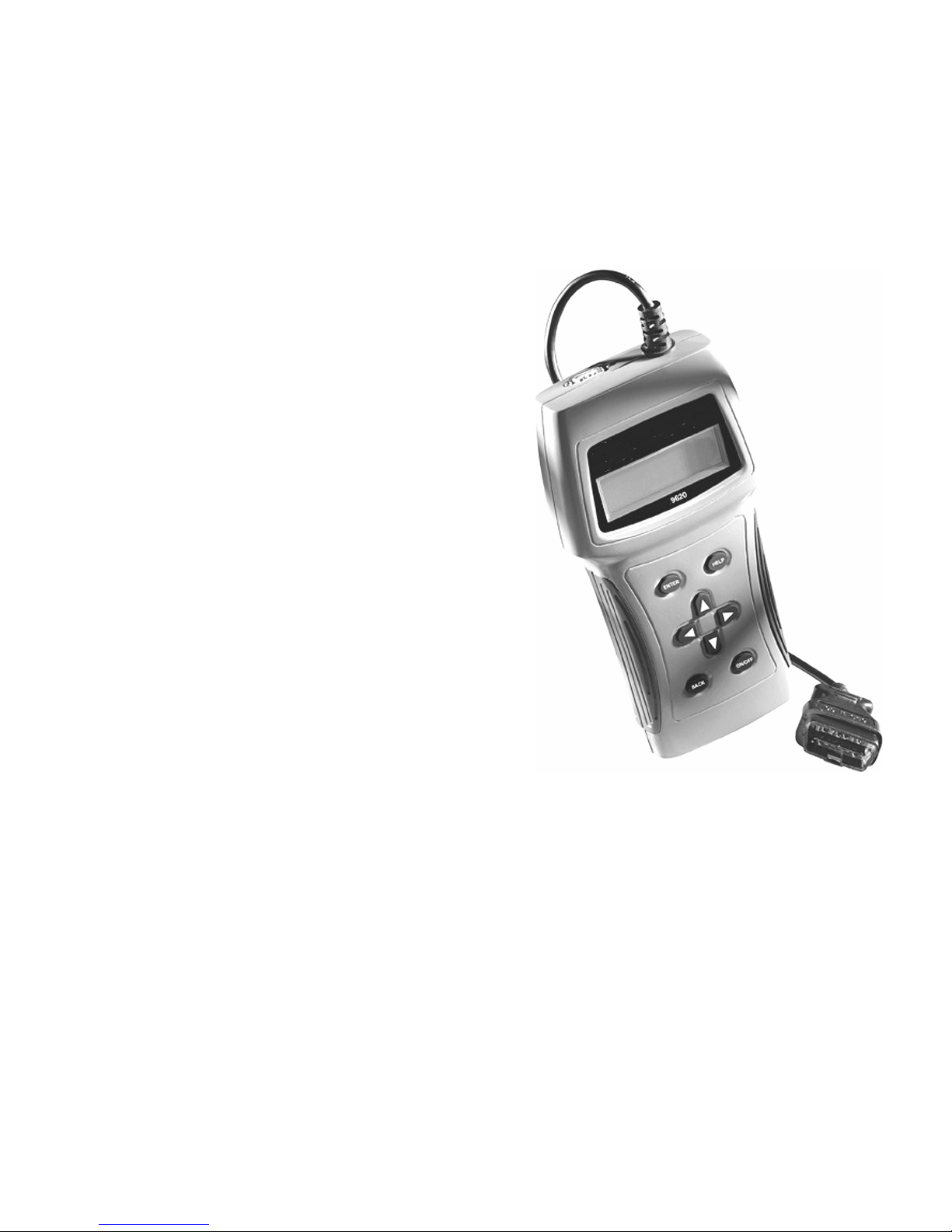
9620 Global
OBD II Scan Tool
©2002 Actron Manufacturing Co.
Printed in USA
0002-002-2361
ACTRON MANUFACTURING CO.
15825 Industria Parkway
C eve and, Ohio 44135-9946
USA
Internet and e-mail - http://www.actron.com
SFI or SEFI:
Sequentia Fue Injection or Sequentia E ectronic Fue Injection. A fue injection system
that uses one or more injectors for each cy inder. The injectors are mounted in the
intake manifo d and are fired individua y.
ST:
Short Term fue trim.
TBI:
Thrott e Body Injection. A fue injection system having one or more injectors mounted in a
centra y ocated thrott e body, as opposed to positioning the injectors c ose to an intake
va ve port. TBI is a so ca ed Centra Fue Injection (CFI) in some vehic es.
TDC:
Top Dead Center. When a piston is at its uppermost position in the cy inder.
Throttle Body:
A device which performs the same function as a carburetor in a fue injection system. On a
thrott e body injection (TBI) system, the thrott e body is both the air door and the ocation of
the fue injectors. On port fue injection systems (PFI, MPFI, SFI, etc.), the thrott e body is
simp y an air door. Fue is not added unti the injectors at each intake port are activated. In
each case, the thrott e body is attached to the acce erator peda .
TPS:
Thrott e Position Sensor. Potentiometer-type sensor connected to the thrott e shaft. Its vo tage
signa output increases as the thrott e is opened. The PCM uses this signa to contro many
systems such as id e speed, spark advance, fue de ivery, etc.
TTS:
Transmission Temperature Sensor. A resistance sensor mounted in the transmission
housing in contact with the transmission f uid. It sends a vo tage signa to the PCM indicating
the temperature of the transmission.
VECI:
Vehic e Emission Contro Information. A deca ocated in the engine compartment containing
information about the emission contro systems found on the vehic e. The VECI is the
authoritative source for determining whether a vehic e is OBD II-comp iant.
VIN:
Vehic e Identification Number. This is the factory-assigned vehic e seria number. This
number is stamped on a number of ocations throughout the vehic e, but the most prominent
ocation is on top of the dashboard on the drivers side, visib e from outside the car. The VIN
inc udes information about the car, inc uding where it was bui t, body and engine codes,
options, and a sequentia bui d number.
VSS:
Vehic e Speed Sensor. Sends a frequency signa to the PCM. The frequency increases as
the vehic e moves faster to give the PCM vehic e speed information used to determine shift
points, engine oad, and cruise contro functions.
WOT:
Wide-Open Thrott e. The vehic e operating condition brought about when the thrott e is
comp ete y (or near y) open. The PCM wi typica y de iver extra fue to the engine and de-
energize the A/C compressor at this time for acce eration purposes. The PCM uses a
switch or the Thrott e Position Sensor to identify the WOT condition.

29620 Professional OBD II Scan Tool
Table of Contents
2.3.9 On-Board Systems ............... 17
2.3.10 Record Data .......................... 17
2.3.11 Vehicle Info ........................... 1
2.3.12 Modules Present ................... 19
2.3.13 Review Data .......................... 19
2.3.14 Print Data .............................. 20
Section 3: Diagnostic Trouble
Codes (DTC) ---- 22
3.1 DTC For at .................................. 22
3.2 Code Lookup ................................ 23
3.3 Diagnostic Trouble Code Ranges 24
Section 4: Help and Trouble-
shooting Tips ---- 25
4.1 How to Use Help ........................... 25
4.2 Scan Tool Proble s ..................... 25
4.2.1 Scan Tool does not powerup:
25
4.2.2 Scan Tool does not Link
withvehicle:........................... 25
4.2.3 One or more modules drops
the communication link: ...... 26
4.2.4 Keyboard does not function
properly: ................................ 26
4.3 Tool Self-Tests .............................. 26
4.3.1 Display Test ........................... 26
4.3.2 Keyboard Test ....................... 26
4.3.3 Memory Test .......................... 27
4.3.4 Printer Test ............................ 27
4.4 Technical Support ........................ 27
Appendi A: Global OBD II PID
List & Definitions 28
Appendi B: Glossary & Defini-
tions ---------------- 31
A information, i ustrations and specifications contained in this manua are based
on the atest information avai ab e from industry sources at the time of pub ication.
No warranty (expressed or imp ied) can be made for its accuracy or comp eteness,
nor is any responsibi ity assumed by Actron or anyone connected with it for oss or
damages suffered through re iance on any information contained in this manua or
misuse of accompanying product. Actron reserves the right to make changes at any
time to this manua or accompanying product without ob igation to notify any person
or organization of such changes.
Vehicle ServiceInformation ......3
Safety Precautions .....................4
Section 1: Vehicle Computer
Systems------------- 5
1.1 Introduction ..................................... 5
1.1.1 What The Computer Controls . 5
1.1.2 What Has Not Changed ..........5
1.1.3 Computer Control System ......5
1.2 Data Link ConnectorandLocation .6
1.3 OBD II Scan Tool Hookup ................6
1.3.1 Keyboard .................................7
1.3.2 Display .....................................7
1.3.3 Lists, Menus, and Questions ...7
1.4 Tool Setup ....................................... 8
1.4.1 Changing Measurement Units
1.4.2 Changing Display Contrast .....
1.4.3 Displaying Tool Information ....9
1.4.4 Program Mode .........................9
1.5 Personal Co puter (PC) and
PrinterInterface..............................9
1.6 Replacing the Battery .....................9
1.7 AC Adapter ......................................9
Section 2: Diagnosing with
theScan Tool ---- 10
2.1 Preli inary Checks ..................... 10
2.2 Connecting the Scan Tool ............ 10
2.3 OBD II Functions List ..................... 11
2.3.1 I/M Readiness ........................ 11
2.3.2 Read Codes .......................... 12
2.3.3 Pending Codes ..................... 12
2.3.4 Erase Codes ......................... 13
2.3.5 View Data .............................. 13
2.3.6 View Freeze Data ................. 15
2.3.7 O2 Monitor Test ..................... 15
2.3. Non-Continuous Tests .......... 16
9620 Professional OBD II Scan Tool 35
M/T:
Manua transmission or manua transax e.
MAF:
Mass Air F ow Sensor. Measures the amount and density of air entering the engine and
sends a frequency or vo tage signa to the PCM. The PCM uses this signa in its fue de ivery
ca cu ations.
MAP:
Manifo d Abso ute Pressure Sensor. Measures intake manifo d vacuum or pressure and
sends a frequency or vo tage signa (depending on sensor type) to the PCM. This gives the
PCM information on engine oad for contro of fue de ivery, spark advance, and EGR f ow.
MAT:
Manifo d Air Temperature sensor. A resistance sensor in the intake manifo d that sends a
vo tage signa to the PCM indicating the temperature of the incoming air. The PCM uses this
signa for fue de ivery ca cu ations.
MIL:
Ma function Indicator Lamp. The MIL is most common y known as the Check Engine or
Service Engine Soon ight. A required on-board indicator to a ert the driver of an emission-
re ated ma function.
Monitor:
A test performed by the on-board computer to verify proper operation of emission re ated
systems or components.
MPFI or MFI:
Mu ti-Port Fue Injection. MPFI is a fue injection system using one (or more) injector(s) for
each cy inder. The injectors are mounted in the intake manifo d, and fired in groups rather
than individua y.
NOx:
Oxides of Nitrogen. A po utant. The EGR system injects exhaust gases into the intake
manifo d to reduce these gases at the tai pipe.
O2S:
Oxygen Sensor. Generates a vo tage of 0.6 to 1.1 vo ts when the exhaust gas is rich ( ow
oxygen content). The vo tage changes to 0.4 vo ts or ess when the exhaust gas is ean
(high oxygen content). This sensor on y operates after it reaches a temperature of
approximate y 349°C (660°F). O2 sensors are usua y found both upstream and downstream
of the cata ytic converter. The PCM uses these sensors to fine tune the air-fue ratio and to
monitor the efficiency of the cata ytic converter. See Bank 1, Bank 2, Sensor 1, Sensor 2.
ODM:
Output Device Monitor.
OBD II:
On-Board Diagnostics, Second Generation. OBD II is a U.S. Government-mandated standard
requiring a cars and ight trucks to have a common data connector, connector ocation,
communication protoco , DTCs and code definitions.
Sensor:
Any device that reports information to the PCM. The job of the sensor is to convert a parameter
such as engine temperature into an e ectrica signa that the PCM can understand.
Sensor 1:
A standard term used to identify the ocation of oxygen sensors. Sensor 1 is ocated upstream
of the cata ytic converter. See O2S, Bank 1, Bank 2.
Sensor 2:
A standard term used to identify the ocation of oxygen sensors. Sensor 2 is ocated
downstream of the cata ytic converter. See O2S, Bank 1, Bank 2.
Solenoid:
A device consisting of an e ectrica coi which when energized, produces a magnetic fie d in
a p unger, which is pu ed to a centra position. A so enoid may be used as an actuator in a
va ve or switch.

9620 Professional OBD II Scan Tool 3
Vehicle ServiceInformation
The following is a list of publishers who have manuals containing electronic engine
control diagnostic information. Some manuals may be available at auto part stores
or local public libraries. For others, write for availability and pricing, specifying the
make, model and year of vehicle.
Service Manuals:
Chilton Book Company
Chilton Way
Radnor, A 19089
Haynes Publications
861 Lawrence Drive
Newbury ark, CA 91320
Cordura Publications
Mitchell Manuals, Inc.
ost Office Box 26260
San Diego, CA 92126
Motors Auto Repair Manual
Hearst Company
250 W 55th Street
New York, NY 10019
Manufacturer Service Manuals:
General Motors:
Buick, Cadillac, Chevrolet, GEO,
GMC, Oldsmobile, & Pontiac
Helm Incorporated
ost Office Box 07130
Detroit, MI 48207
Saturn
Adistra Corporation
c/o Saturn ublications
101 Union St.
ost Office Box 1000
lymouth, MI 48170
Ford Motor Company:
Ford, Lincoln, & Mercury
Ford ublication Department
Helm Incorporated
ost Office Box 07150
Detroit, MI 48207
Chrysler Corporation:
Chrysler, Plymouth, & Dod e
Chrysler Motors Service Training
26001 Lawrence Avenue
Center Line, MI 48015
Suitable manuals have titles, such as:
Electronic Engine Controls
Fuel Injection and Feedback Carburetors
Fuel Injection and Electronic Engine Controls
Emissions Control Manual
. . . or similar titles
34 9620 Professional OBD II Scan Tool
ESC:
E ectronic Spark Contro . An ignition system function that warns the PCM when knock is
detected. The PCM wi then retard spark timing to e iminate the knocking condition.
EST:
E ectronic Spark Timing. An ignition system that a ows the PCM to contro spark advance
timing. The PCM determines optimum spark timing from sensor information engine speed,
thrott e position, coo ant temperature, engine oad, vehic e speed, Park/Neutra switch
position, and knock sensor condition.
EVAP:
Evaporative Emissions System.
Freeze Fra e:
A b ock of memory containing the vehic e operating conditions for a specific time.
Ground (GND):
An e ectrica conductor used as a common return for an e ectric circuit(s) and with a re ative
zero potentia (vo tage).
Hall Effect Sensor:
Any of a type of sensor uti izing a permanent magnet and a transistorized Ha Effect switch.
Ha Effect type sensors may be used to measure speed and position of the crankshaft or
camshaft for spark timing and fue injector contro .
HO2S:
Heated Oxygen Sensor. See O2S.
IAC:
Id e Air Contro . A device mounted on the thrott e body which adjusts the amount of air
bypassing a c osed thrott e so that the PCM can contro id e speed.
ICM:
Ignition Contro Modu e.
I/M:
Inspection and Maintenance. An emission contro program.
ISC:
Id e Speed Contro . A sma e ectric motor mounted on the thrott e body and contro ed by
the PCM. The PCM can contro id e speed by commanding the ISC to adjust its position.
ISO:
Internationa Organization of Standardization.
Knock:
Uncontro ed ignition of the air/fue mixture in the cy inder. A so referred to as detonation or
ping. Knock indicates extreme cy inder pressures or hotspots which are causing the air/
fue mixture to detonate premature y.
Knock Sensor (KS):
Used to detect engine detonation or knock. The sensor contains a piezoe ectric e ement
and is threaded into the engine b ock. Specia construction makes the e ement sensitive
on y to engine vibrations associated with detonation.
KOEO:
Key On Engine Off.
KOER:
Key On Engine Running.
LCD:
Liquid Crysta Disp ay.
LT:
Long Term fue trim.

49620 Professional OBD II Scan Tool
Safety Precautions
General Sa ety Guidelines to Follow When Working on Vehicles
To prevent accidents that could result in serious injury and/or damage
to vehicle or test equipment, care ully ollow these sa ety rules and
test procedures at all times when working on vehicles:
Always wear approved eye protection.
Always operate the vehicle in a well-ventilated area. Do not inhale exhaust
gases they are very poisonous!
Always keep yourself, tools and test equipment away from all moving or hot
engine parts.
Always make sure the vehicle is in Park (Automatic transmission) or neutral
(manual transmission) and that the parking brake is irmly set. Block the
drive wheels.
Never lay tools on vehicle battery. You may short the terminals together
causing harm to yourself, the tools or the battery.
Never use scan tool if its internal circuitry has been exposed to any liquids.
Never smoke or have open flames near vehicle. Vapors from gasoline and/or
charging battery are highly flammable and explosive.
Never leave vehicle unattended while running tests.
Always keep a fire extinguisher suitable for gasoline/electrical/chemical fires
handy.
Always use extreme caution when working around the ignition coil, distributor
cap, ignition wires, and spark plugs. These components contain high voltage
when the engine is running.
When performing a road test, never operate the scan tool alone while driving
the vehicle. Always have one person drive the vehicle while an assistant
operates the tester.
Always turn ignition key OFF when connecting or disconnecting electrical
components, unless otherwise instructed.
Always follow vehicle manufacturers warnings, cautions and service proce-
dures.
WARNING!
So e vehicles are equipped with safety air bags. You ust follow
vehicle service anual cautions when working around the air bag
co ponents or wiring. If the cautions are not followed, the air bag ay
open up unexpectedly, resulting in personal injury. Note that the air
bag can still open up several inutes after the ignition key is off (or
even if the vehicle battery is disconnected) because of a special
energy reserve odule.
9620 Professional OBD II Scan Tool 33
Closed Loop (CL):
A feedback system that uses the O2 Sensor(s) to monitor the resu ts of combustion.
Based on the signa (s) from the O2 sensor(s), the PCM modifies the air/fue mixture to
maintain optimum performance with owest emissions. In c osed oop mode, the PCM
can fine tune contro of a system to achieve an exact resu t.
CO:
Carbon Monoxide
Continuous Me ory Codes:
See Pending Codes.
CPS:
Crankshaft Position Sensor. Sends a frequency signa to the PCM. It is used to reference
fue injector operation and synchronize spark p ug firing on distributor ess ignition
systems (DIS).
CTS:
Coo ant Temperature Sensor. A resistance sensor that sends a vo tage signa to the
PCM indicating the temperature of the coo ant. This signa te s the PCM whether the
engine is co d or warm.
Data Link Connector (DLC):
Connector providing access and/or contro of the vehic e information, operating
conditions, and diagnostic information. Vehic es with OBD II use a 16-pin connector
ocated in the passenger compartment.
Data Strea :
The actua data communications sent from the vehic es PCM to the data connector.
DEPS:
Digita Engine Position Sensor.
Detonation:
See Knock.
DTC:
Diagnostic Troub e Code. An a phanumeric identifier for a fau t condition identified by
the On Board Diagnostic System.
DI/DIS:
Direct Ignition/Distributor ess Ignition System. A system that produces the ignition spark
without the use of a distributor.
Duty Cycle:
A term app ied to signa s that switch between on and off. Duty cyc e is the percentage of
time the signa is on. For examp e, if the signa is on on y one fourth of the time, then the
duty cyc e is 25%. The PCM uses duty cyc e type signa s to maintain precise contro of an
actuator.
ECT:
Engine Coo ant Temperature sensor. See CTS.
EFI:
E ectronic Fue Injection. Any system where a computer contro s fue de ivery to the engine
by using fue injectors.
EGR:
Exhaust Gas Recircu ation. The PCM uses the EGR system to recircu ate exhaust gases
back into the intake manifo d to reduce emissions. EGR Recircu ation is used on y during
warm engine cruise conditions. EGR f ow at other times can cause sta ing or no starts.
EPA:
Environmenta Protection Agency.

9620 Professional OBD II Scan Tool 5
Section 1: Vehicle Computer Systems
1.1 Introduction
This section describes the engine computer contro system, types of sensors and how
the computer contro s engine fue de ivery, id e speed and timing. Additiona information
may be found in the technica support books at your oca ibrary or auto parts store. The
more known about the computer system, the easier the prob em can be diagnosed.
Computer contro s were origina y insta ed on vehic es to meet federa government
regu ations for ower emission eve s and improved fue economy. This began in the ear y
1980s when basic mechanica systems were no onger ab e to accurate y contro key
engine parameters. A computer cou d be programmed to contro the engine under various
operating conditions, making the engine more re iab e. Whi e these ear y systems were
very imited in scope of their diagnostics, providing on y 10-14 troub e codes, they did he p
guide the vehic e repair process.
In 1994, manufacturers began equipping vehic es with a new c ass of computer techno ogy
which puts more processing power under dash than ever before. It is ca ed On-Board
Diagnostics version II, or OBD II. It is required on a vehic es so d in the US beginning
January 1, 1996 (though most domestic manufacturers introduced it ear ier than required),
and offers increased system monitoring and diagnostic information. This new system stores
a ibrary of more than 650 genera troub e codes and another approximate y 400
manufacturer-specific codes, a of which can be accessed with the scan too . These codes
cover Body Systems (B-Codes), Chassis Systems (C-Codes), Communications Codes
(U-Codes), and Powertrain Systems (P-Codes). Now, basic terms are standardized and
a generic codes wi share a common format and termino ogy that manufacturers and the
Society of Automotive Engineers (SAE) designed.
The OBD II Professiona Scan Too performs OBD II functions on ALL makes of OBD II
comp iant vehic es from 1994 and up.
1.1.1 What The Computer Controls
The main contro areas of the vehic e computer are fue de ivery, id e speed, spark advance,
and emissions contro s. Some on-board computers may a so contro the transmission,
brakes, and suspension systems as we .
1.1.2 What as Not Changed
A computer-contro ed engine is very simi ar to the o der, non-computerized engine. It is sti
an interna combustion engine with pistons, spark p ugs, va ves, and camshaft(s). The ignition,
charging, starting, and exhaust systems are very simi ar as we . Test and repair of these
systems are the same as before. The technica manua s for these components provide
instruction on how to perform the tests. Additiona y, compression gauges, vacuum pumps,
engine ana yzers, and timing ights wi continue to be used.
1.1.3 Computer Control System
The vehic e on-board computer, or Powertrain Contro Modu e (PCM), is the heart of the
system. It is sea ed in a meta box and connected to the rest of the engine by a wiring
harness. The PCM is common y ocated in the passenger compartment, behind the
dashboard (kick pane position), a though some manufacturers ocate the PCM in the
engine compartment. The PCM is programmed by the factory. The program is a comp ex
ist of ookup tab es and instructions te ing the computer how to contro the engine based
on various driving conditions. It does this using sensors to monitor what is happening and
then provide feedback through a network of switches and actuators throughout the vehic e.
32 9620 Professional OBD II Scan Tool
Appendix B:Glossary Definitions
A/C:
Air Conditioning.
A/F:
Air/Fue ratio. The proportion of air and fue de ivered to the cy inder for combustion. For
examp e, an A/F ratio of 14:1 denotes 14 times as much air as fue in the mixture. A
typica idea A/F ratio is 14.7:1.
AC Clutch Relay:
The PCM uses this re ay to energize the A/C c utch, turning the A/C system on or off.
AC Pressure Sensor:
Measures air conditioning refrigerant pressure and sends a vo tage signa to the
PCM.
AC Pressure Switch:
A mechanica switch connected to the A/C refrigerant ine. The switch is activated
(sending a signa to the PCM) when the A/C refrigerant pressure becomes too ow.
Actuator:
Actuators such as re ays, so enoids, and motors a ow the PCM to contro the operation
of vehic e systems.
Air Injection Reaction (AIR) Syste :
An emission contro system operated by the PCM. During co d starts, an air pump
injects outside air into the exhaust manifo d to he p burn hot exhaust gases. This
reduces po ution and speeds warm-up of oxygen sensors and cata ytic converters.
After the engine is warm, the air wi either be dumped back to the atmosphere (or into
the air c eaner assemb y) or sent to the cata ytic converter.
Bank 1:
The standard way of referring to the bank of cy inders containing cy inder #1. In- ine
engines have on y one bank of cy inders. Most common y used to identify the ocation of
oxygen sensors. See O2S, Sensor 1, Sensor 2.
Bank 2:
The standard way of referring to the bank of cy inders opposite cy inder #1. Found on V-
6, V-8, V-10, etc. and horizonta y opposed engines. Most common y used to identify the
ocation of oxygen sensors. See O2S, Sensor 1,Sensor 2.
BARO:
Barometric Pressure Sensor. See MAP Sensor.
Boost Control Solenoid:
A so enoid that is energized by the PCM, in order to contro supercharger boost pressure.
Brake Switch Signal:
An input signa to the PCM indicating that the brake peda is being pressed. This signa
is typica y used to disengage Cruise Contro systems and Torque Converter C utch
(TCC) so enoids. See a so TCC.
CAM:
Camshaft Position Sensor. Sends a frequency signa to the PCM in order to synchronize
fue injector and spark p ug firing.
CARB:
Ca ifornia Air Resources Board. Governing body for emissions contro in Ca ifornia.
CKP REF:
Crankshaft Position Reference.
69620 Professional OBD II Scan Tool
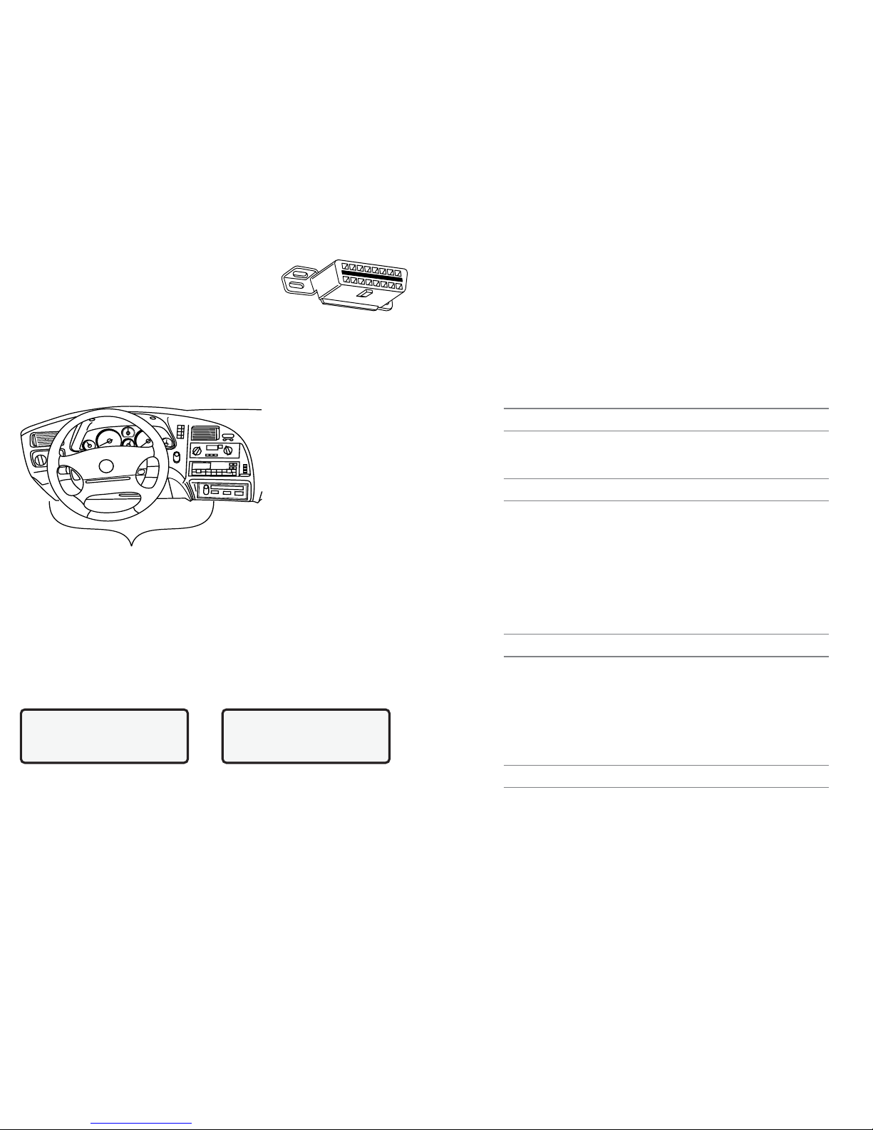
DLC Location
1.2 Data Link ConnectorandLocation
The tester communicates with the vehic e PCM via a data
ink connector (DLC) a so referred to as a J1962
connector. The term J1962 is taken from physica and
e ectrica specification number assigned by SAE (Society of
Automotive Engineers). A standardized DLC means a comp iant
vehic es wi use the same DLC with the generic ink information avai ab e on the same
pins regard ess of vehic e make or mode . In addition to the connector definitions, is a
guide ine on where the connector is to be ocated in the vehic e. This guide ine states
that the DLC shou d be ocated under the dashboard on the driver side of the vehic e.
However, not a OBD II DLCs are ocated under the dash on the driver side. If required,
refer to vehic e service documentation for the DLC ocation.
1.3 OBD II Scan Tool Hookup
The OBD II cab e attached to the scan too fits the OBD II DLC. Because the OBD II J1962
connector contains dedicated pins for power and ground, on y a sing e cab e connection is
required for both scan too power and PCM communication.
Connect the scan too to the DLC. This connection wi provide power for the scan too .
The DLC maintains power even when the ignition is turned off. Therefore, connection to
the battery is not required.
When the scan too powers up, a series of screens are disp ayed. The screens start with
a We come screen and end with a Key Button He p screen.
The screens between the We come screen and the Key Button He p screen are for
too se f-tests and software ID. Refer to this software ID when contacting the Actron
technica support ine with a prob em. To review the key button definitions, push the
(HELP) key; otherwise, press ENTER to continue.
The scan too requires a minimum of 8 vo ts to power up. If a prob em occurs with power-
up, review Section 4: Help and Troubleshooting Tips.
Welcome To
The Global OBDII
SCANTOOL
Press HELP For Key |
Bu on Informa ion
Press ENTER To Con
9620 Professional OBD II Scan Tool 31
REL TPS (0 - 100%)
Relative Throttle Position is re ative thrott e position at norma position.
SECOND AIR (AIR_STAT: UPS, DNS or OFF)
Commanded Secondary Air Status is on newer vehic es and actuators to contro po u-
tion contro .
UPS - UP STREAM modu e is demanding that secondary air be added at exhaust
manifo ds
DNS - DOWN STREAM modu e is demanding secondary air be added at cata ytic
converter
OFF - Modu e is demanding no secondary air to be added.
ST FTRMxy (-100 - 99.22%)
Short-term Fuel Trim Bank ca cu ated va ue represents the short-term re ation of fue
metering on a fue -injected engine.
NOTE: Short-term Fuel Trim calculated value that ha a po itive percentage i a rich fuel
trim and if a negative percentage i pre ent the fuel trim i lean.
ST FLTRMx (-100 - 99.2%)
Short-term Fuel Trim va ue represents the short-term re ation of fue metering on a fue -
injected engine.
NOTE: Short-term Fuel Trim value with a po itive percentage i a rich fuel trim and if a negative
percentage i pre ent the fuel trim i lean.
THR POS (0 - 100%)
Absolute Throttle Position is the position the thrott e is ocated. The more the thrott e is
c osed the ess percent shown.
THROT CMD (0 - 100%)
Commanded Throttle Actuator Control is the position of the thrott e. If thrott e is c osed the
percent wi be 0 and if wide open 100%.
TRIPS SNC CLR (0 - 255)
Number of warm-ups since diagnostic trouble codes cleared. Warm-up is when temperature
of coo ant rises to at east 22°C (40°F) from engine starting and reaching a minimum tempera-
ture of 70°C (160°F). If a diese engine the engine minimum temperature is 60°C (140°F.)
NOTE: If there i more than 255 that the engine warm up the TRIPS SNC CLR will remain
at 255.
TROUB CODE (00 00 - FF FF)
Trouble Code Parameter wi give the diagnostic troub e code that caused a freeze
frame capture. This information is he pfu in diagnosing the cause of a driveabi ity. If no
freeze frame data has been captured this PID wi be zero.
VEH SPEED (0 - 255K/h) or (0 - 158 ph)
Vehicle Speed shows the speed the vehic e is going.
VPWR (0 - 65.535V)
Control Module Voltage is the power input to the contro modu e.
NOTE: 42-volt vehicle may utili e multiple voltage for different y tem on the vehicle.
VPWR may be ignificantly different than battery voltage.

9620 Professional OBD II Scan Tool 7
1.3.1 Keyboard
The scan too software was designed for easy to operate approach in navigating through
operationa menus. Simp y fo ow instructions that match keyboard symbo s.
Keyboard Functions
The scan too uses 8 keys to navigate through the software-user interface:
ENTER Used to se ect or answer a software request.
HELP Used to request he p when the (|) symbo is disp ayed in the ower right hand
corner of the disp ay.
BACK Used to move one screen back in scan too f ow.
ARROWS
UP/DOWN Used to move the so id cursor (`) in the direction of the arrow or scro
the data ist in the direction you want to move the ist.
LEFT/RIGHT Used to se ect and dese ect items in custom ists. This key is a so
used to answer questions by se ecting yes or no.
ON/OFF Used to turn scan too ON and OFF when not powered by vehic e. Momen-
tari y press and re ease button when turning ON to a ow boot process.
1.3.2 Display
The scan too has a 4 ine x 20 character back it
Liquid Crysta Disp ay (LCD) for easy viewing. The
back ighting is disab ed when the scan too is
powered by its interna batteries. This gives the
user a arge viewing area to disp ay most He p
and Instructiona messages. It puts more
information on the disp ay instead of having to refer to printed materia s. Again the disp ay wi
support a number of he pfu characters that wi prompt the user through test routines. These
characters are shown be ow:
|Question Mark in ower right corner means there is help avai ab e for this screen or
current se ectab e item.
`Pointer (cursor) is used to indicate current se ectab e choice.
[Down Arrow indicates there is additiona information on the next screen.
]Up Arrow indicates there is additiona information on previous screen.
«Diamond to the eft of item indicates it is se ected.
The screen at the right shows how some of these symbo s wi ook on your disp ay.
1.3.3 Lists, Menus, and Questions
The scan too is designed to be as intuitive as possib e. Its functions and contro s are easy to
understand and use. A menu and screen ists operate the same way. Use the UP/DOWN
arrow keys to move the cursor to a se ection. The ENTER key se ects that function or item. The
screen examp es be ow show a few se ections avai ab e on the OBDII Function List.
For examp e: to read vehic es DTCs, move cursor to Read Codes and press ENTER.
To make a different choice, use the DOWN arrow key to move the cursor down to View Data
and press ENTER. This wi se ect the View Data function.
Sometimes, a ist wi be onger than three or four items, and wi not fit on a sing e screen. In
this case, the DOWN arrow symbo ([) is visib e in the ast co umn of the disp ay, indicating
that there are more choices on the next screen, as shown be ow on the eft. Use the DOWN
arrow key to move the cursor down the ist.
OBDII Func ion Lis |
3)Erase Codes ]
4)View Da a [
`5)View Freeze Da a
30 9620 Professional OBD II Scan Tool
IAT TEMP (-40 - 215°C) or (-40 - 419°F)
Intake Air Temperature is a measure of intake air temperature to determine correct air/
fue ratios and spark timing operations.
IGN ADV (-64 - 63.5°)
Ignition Timing Advance for cy inder is a signa of how much spark advance to add to
base engine timing (expressed in crankshaft degrees).
LT FL FTRM (-100 - 99.22%)
Long Term Fuel Trim Bank is the fue mixture adjustment in a range with midpoint being 0.
NOTE: Po itive reading indicate module commanded a long-term rich mixture correction
in re pon e to a lean operating condition. A negative reading indicate module ha
commanded a long-term lean mixture in re pon e to a rich operating condition.
MAF (0 - 655.35 g/s) or (0 - 86.5lb/ in)
Mass Air Flow is the air f ow rate the sensor sends to the computer modu e indicating
mass of air entering engine.
MAP (0 - 255kPa) or (Hg)
Intake Manifold Absolute Pressure disp ays manifo d pressure.
MIL DIST (0 - 65535k ) or (0 - 40,722 iles)
Distance Traveled while Malfunction Indicator Lamp is Active is a counter that disp ays
distance trave ed since Check Engine or Service Engine Soon ight came on.
MIL STAT (ON or OFF)
Monitor Status Data Trouble Code state that modu e is commanding the Ma function Indicator
Lamp (MIL) to be ON if prob em exists.
MIL TIME (0 - 65535 in) or (0 - 1092.25Hrs)
The distance trave ed since the MIL (Check Engine or Service Engine Soon ight) came on.
O2Sxy (0 - 1.275V)
Oxygen Sensor Output Voltage is the vo tage generated from the oxygen sensor to
increase and decrease the amount of exhaust gas.
O2Sxy (-128 - 127.996 A)
Oxygen Sensor Output Current is used for inear or wide ratio oxygen sensors to increase
and decrease the amount of exhaust gas
OBD2 STAT (CA, OBDI, US, NONE, EU and/or JA)
On Board Diagnostic how what vehicle wa made for.
Data Parameter :
CA - Indicate te t vehicle meet California on board diagno tic ARB requirement
OBD I - Indicate te t vehicle doe not meet OBDII requirement .
US - Indicate te t vehicle meet Federal EPA requirement .
NONE - Indicate te t vehicle i not on board diagno tic compliant.
EU - Indicate te t vehicle meet European on board diagno tic requirement.
JA - Indicate te t vehicle meet Japane e on board diagno tic requirment.Outside Air
Temperature give temperature out ide.
NOTE: The Data Parameter can be u ed with each other for example CA/US
OUTSID AIR (-40 - 215°C) or (-40 - 419°F)
Outside Air Temperature gives temperature outside.
PTO STATUS (OFF or ON)
Power Take Off Status a ows modu e to keep track of Power at Take-Off.
REL FRP (0 - 5177.27kPa) or (750.9PSI)
Relative Fuel Rail Pressure (Vacuum) is the fue rai pressure at engine.

89620 Professional OBD II Scan Tool
At the bottom of the ist, there is now on y an UP arrow symbo (]) visib e in the ast
co umn indicating the ast function in the ist has been reached. To return to previous
screens, press the UP arrow key. The UP/DOWN arrow keys work the same way when
scro ing through text such as the He p screen.
The Scan Too may ask a question which requires a response from user. These wi
a ways be YES or NO questions, and are answered with cursor and Arrow keys.
In these screens, brackets <> wi automatica y appear next to defau t response. To
accept defau t choice, simp y press ENTER. Use LEFT/RIGHT arrow key to move brackets
to other response and press ENTER.
1.4 Tool Setup
On y functions of the Main Menu that pertain to getting started with scan too are discussed
in the fo owing paragraphs. For a other menu se ections avai ab e, refer to Section 4:
Help and Troubleshooting Tips.
Too Setup is used to change the scan too defau t
unit settings. To change the scan too settings,
se ect Tool Setup from the MAIN MENU and
press the ENTER key.
NOTE: Setting cho en will remain until 9 volt battery i dead.
1.4.1 Changing Measurement Units
After se ecting Too Setup option, too setup menu appears. To choose Eng ish or Metric
measurement units, use UP/DOWN arrows to make se ection and press ENTER. The
disp ay wi ook ike the fo owing screen:
1.4.2 Changing Display Contrast
From the Too Setup menu, se ect Display Contrast and press ENTER. Use the UP/
DOWN arrow keys as indicated on the screen:
View Ins ruc ions
For Crea ing Cus om
Da a Lis ?
Yes <No>
OBDII Func ion Lis |
`1) I/M Readiness
2)Read Codes [
3)Pending Codes
OBDII Func ion Lis |
4)View Da a ]
5)View Freeze Da a [
`6)Record Da a
Se up Tool For
1) English/Me ric
`2)Display Con ras
3)Tool Informa ion
]Increase Con ras
[Decrease Con ras
Press ENTER To Save
Se up Tool For
`1) English/Me ric
2)Display Con ras [
3)Tool Informa ion
Measuremen Uni s
`English(Defaul )
Me ric
9620 Professional OBD II Scan Tool 29
CLR DST (0k -65,535k ) or (0- 40,722 iles)
Distance Since Cleared Diagnostic Codes is distance since diagnostic troub e codes
were erased.
CLR TIM (0 - 65535 in or 1092.25 hours)
Time Since Cleared Diagnostic Code is time since diagnostic troub e codes were erased.
CMD EQ RATxy (0 - 1.99)
Commanded Equivalence Ratio is the ratio of the air/fue mixture.
NOTE: The CMD EQ RAT will read 1.0 while in a clo ed loop of fuel
COOLANT (-40 - 215°C)or(°F)
Engine Coo ant Temperature disp ays engine coo ant temperaturefrom engine coo ant
temperature or cy inder head temperature sensor.
NOTE: The coolant on many die el may u e Engine Oil Temperature in tead.
EGR CMD (0 - 100%)
Commanded Exhaust Gas Recirculation is the percentage of exhaust gas being recir-
cu ated.
EGR ERR (-100 - 99.22%)
Exhaust Gas Recirculation Error wi show the error from changing from one condition to
another.
ENG RUN (0 - 65,535sec.)
Time since Engine Strart is the time the engine is running.
NOTE: ENG RUN top when engine tall or engine i turned off for any rea on.
ENGINE (0 - 16383.75 RPM)
Engine Revolutions Per Minute (RPM) is the speed engine is running.
EQ RATxy
O2 Sensor Equivalence Ratio for Bank x Sensor y.
EVAP REQ (0-100%)
Commanded Evaporative Purge is the position evaporative purge contro va ve is open
in percentage.
EVAP VP (-8192PA - 8191PA) OR (-32.8878 - 32.8838 H2O)
Evaporative Emissions System Vapor Pressure is pressure in the fue tank
FUEL LVL (0 - 100%)
Fuel Level Input is the percentage of fue with 0% equa ing tank is fu and 100% when tank
is empty.
FUEL PRES (0 - 765kPa) or (0 - 110psi)
Fuel Rail Pressure is the fue pressure at the engine in respect to atmospheric pres-
sure.
FUEL SYS (OPEN or CLSD)
Fuel System Status show oop status of fue system banks.
OPEN: Computer modu e is operating in Open Loop contro strategy. The vehic e has
not yet satisfied conditions for the computer modu e to go to c osed oop.
CLSD: Computer modu e current y functioning in C osed oop contro strategy, using
O2 sensor(s) as feedback for fue contro .
OPEN1: Open Loop contro strategy is being used by the PCM due to driving conditions
power enrichment and dece eration enrichment.
OPEN2: Computer modu e is operating in Open Loop contro strategy due to detected
system fau t. Certain actuator or sensor fau ts are usua y the cause.
CLSD1: C osed Loop contro is current storage being used by PCM, but a fau t with at
east one O2 sensor has been detected. The contro system may be using
sing e O2 for fue contro ca cu ations.

9620 Professional OBD II Scan Tool 9
1.4.3 Displaying Tool Information
From Too Setup menu, se ect Tool Infor ation and press ENTER. Use UP/DOWN
arrow keys to view information. Record information in case the need to contact customer
service arises.
1.4.4 Program Mode
Used to update scan too s software. Instructions wi be provided with updates.
1.5 Personal Computer (PC) and PrinterInterface
Scan too is equipped with a standard 9 pin seria interface. Use connection to attach
too to a PC or compatib e printer.
Personal Computer
Use seria adapter to connect to a PC when updating to current avai ab e software.
Software updates may be purchased from Actron by ca ing the to free number
provided or from the Actron website: www.actron.com.
Refer to Section 2.4.13 Print Data for defau t seria port settings and to make
changes to settings.
Printer Connection
Connect a compatib e printer cab e to the scan too and Printer using specifications
be ow:
- If the printer connector is a 25 pin connector or if the gender is not compatib e, an
adapter wi be required.
- Adapters are avai ab e at most oca PC stores or e ectronics out ets.
- A NULL modem adapter is required to be connected in series with scan too and
printer cab e.
1.6 Replacing the Battery
To rep ace the 9V battery, do the fo owing:
Remove screw from back of scan too case.
S ide battery cover back to disengage hooks.
Rep ace 9V battery and p ace in compartment.
S ide battery cover up, making sure hooks engage scan too case.
Insta screw.
1.7 AC Adapter
The AC power adapter powers the too when you review codes and print off-vehic e and when
you update the software via a persona computer. The Scan too is equipped to accept any
110 Vac12 Vdc AC adapter with the fo owing specifications.
300 mA minimum unregu ated wa power adapter.
Dimensions - 5.5 mm Outside Diameter, 2.5 mm Inside Diameter.
Se up Tool For
1) English/Me ric
2)Display Con ras
`3)Tool Informa ion
Tool Informa ion:
`Serial No: 1360447]
SW ID: 86E3H[
HW Ver: 1
POS
NEG
28 9620 Professional OBD II Scan Tool
Appendix A: Global OBD II PID List
Definitions
A parameter identification data (PID) isted was verified on actua vehic es to guarantee
accuracy. Definitions used to describe a PIDs were obtained from re iab e sources and
are accurate at time of printing. It is possib e that some newer vehic es may contain different
data different from that isted. In these cases, refer to an app icab e vehic e service manua .
Data Para eter List For at
The PID ist is organized in a phabetica order the same way the scan too does. For each
PID, the type of reading are provided. Remember to a ways refer to a vehic e service manua
for detai ed diagnostic procedures for troub eshooting incorrect PID readings.
Types of Data Para eters
INPUT: These data parameters are obtained from sensor outputs. Sensor outputs
are inputs to vehic es computer modu e(s). For examp e, if an Oxygen Sen-
sor was generating a 400mV signa , then the scan too disp ays O2S (v) 0.40.
OUTPUT: These data parameters are outputs or commands that come direct y from
computer modu e(s). For examp e; the ignition spark advance is contro ed
by PCM, on most vehic es, monitoring this PID shows spark output from
PCM. The scan too wou d disp ay IGN ADV(°) 10.
CALCULATED: These data parameters are ca cu ated after ana yzing various inputs to the
vehic es computer modu e(s). For examp e, the engine oad. The PCM
ca cu ates this from sensor inputs and disp ays it in a percentage.
PCM VALUE: Is information that is stored in the computer modu e(s) memory and deter-
mined to be usefu to service technician. An examp e of this is TROUBLE
CODE va ue, the DTC that caused a freeze frame capture.
NOTE: Several different cau e can have the ame parameter indication. For information on
diagno tic con ult vehicle ervice manual .
DATA PARAMETER LIST
ABS FRP (0 - 655350kPA) or (0 - 95050.5PSI)
Absolute Fuel Rail Pressure is the fue pressure at the engine when reading in refer-
ence to atmospheric pressure.
ABS LOAD (0 - 100%)
Absolute Load Value is the norma va ue of air mass per intake stroke disp ayed as a
percent.
ABSLT TPS (0 - 100%)
Absolute Throttle Position represents norma distance thrott e is opened.
ACC POS D,E or F (0 - 100%)
Accelerator Pedal Position represents norma distance gas peda is pressed.
BARO PRESS (0 - 255kPA) or (0 - 36.9PSI)
Barometric Pressure is norma y received from a dedicated barometer, manifo d abso-
ute pressure sensor and other inputs during certain modes of driving.
NOTE: The Baro Pre may not be the ame a ome weather ervice Barometric
Pre ure due to being read at ea level.
CALC LOAD (0 - 100%)
Calulated LOAD Value indicates oad on engine.
CAT TEMPxy (-40°C - 6513.5°C) or (-40 - 9999.9F)
Catalyst Temperature Bank sha disp ay cata yst substrate temperature for bank cata-
yst, if used by contro modu e strategy for on board diagnostics monitoring, bank,
sensor cata yst or temperature sensor.
10 9620 Professional OBD II Scan Tool
Diagnostic
Connector
Section 2: Diagnosing with theScan Tool
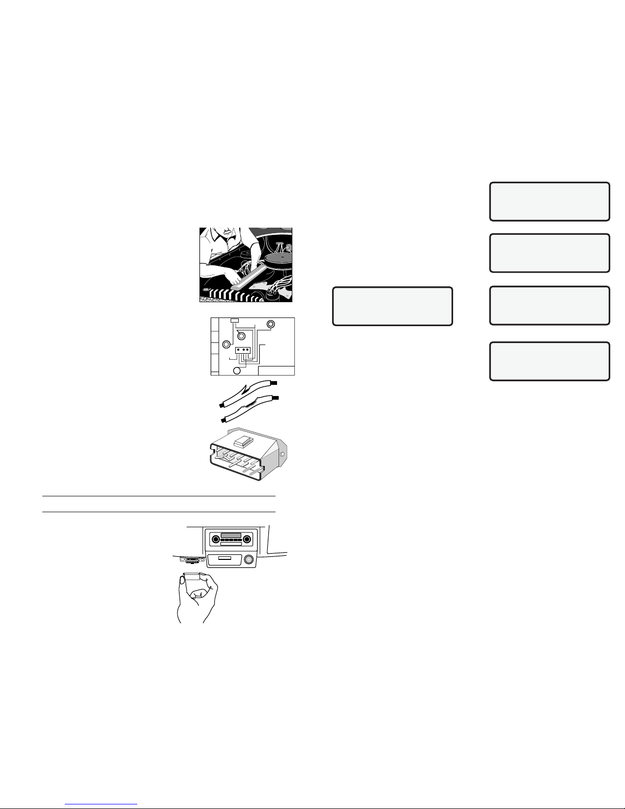
2.1 Preliminary Checks
Before using scan too , perform a comp ete visua inspection. Many driveabi ity prob ems
are found by visua inspection, saving time. Check the fo owing items before proceeding
with scan too testing:
1. Has vehic e been serviced recent y? Sometimes
things get connected in the wrong p ace, or not at a .
2. Dont take shortcuts. Inspect hoses and wiring which
may be difficu t to see because of ocation beneath air
c eaner housings, a ternators and simi ar
components.
3. Inspect air c eaner and ductwork for defects.
4. Check sensors and actuators for damage.
5. Inspect a vacuum hoses for:
Correct routing. Refer to vehic e service manua , or
Vehic e Emission Contro Information (VECI) deca
ocated in engine compartment.
Pinches and kinks.
Sp its, cuts or breaks.
6. Inspect wiring for:
Contact with sharp edges (this happens frequent y).
Contact with hot surfaces, such as exhaust manifo ds.
Pinched, burned or chafed insu ation.
Proper routing and connections.
7. Check e ectrica connectors for:
Corrosion on pins.
Bent or damaged pins.
Contacts not proper y seated in housing.
Bad wire crimps to termina s.
Connector prob ems are common in engine contro
system. Inspect for corrosion, bent, pushed out, or over
expanded pins.
Note: Some connector u e pecial grea e on contact to prevent corro ion. Do not wipe
off! Obtain grea e, from vehicle dealer. It i a pecial type for thi purpo e.
2.2 Connecting the Scan Tool
Remove protective cap from data ink connector,
if present. Connect scan too and fo ow scan
too prompts. Use scan too 9V battery to do se f-
tests, review codes, code ookup or print data
when connection to vehic e is not required.
When scan too powers up, a series of screens
are disp ayed. The screen starts with We come
and ends with a Key Button He p.
FRONT
OF CAR
HVAC
CRUISE
BRAKE BOOSTER
TO TRANS
MOD E
EGR
VAC
REG
FUEL
PRESS
REG
EGR
VAC
REG
9RAC2LAB
T
ER
P
A.
M
9620 Professional OBD II Scan Tool 27
4.3.3 Memory Test
Perform the Me ory Test if the scan too has
troub e disp aying code definitions or performing
functions that use interna memory. Se ect
Me ory Test from the Too Se f-Test menu and
press the ENTER key.
The test begins immediate y and disp ays a
message Memory Test fo owed by periods as
interna memory is tested.
When done, a message disp ays indicating
whether the test passed or fai ed. Press ENTER
to return to the Too Se f-Test menu.
4.3.4 Printer Test
If you cannot print from the scan too , se ect
Printer Test and press the ENTER key. Refer to
section Changing the Printer Settings on
page20.
4.4 Technical Support
1-800-228-7667 (8:00 - 6:00 EST Monday - Friday), or send emai to
Memory Tes Passed!
Press ENTER To Con
Memory Tes Failed
SW ID = F1E8
Press ENTER To Con
Tool Self-Tes |
1) Display Tes
2) Keyboard Tes [
`3) Memory Tes
Memory Tes . . . . .
. . . . . . .
Tool Self-Tes |
2) Keyboard Tes ]
3) Memory Tes
`4) Prin er Tes

9620 Professional OBD II Scan Tool 11
After pressing ENTER from HELP Screen, the
Main Menu disp ays. Se ect Vehicle Diagnosis
and press ENTER.
The scan too asks to erase data from previous
test. Use LEFT/RIGHT arrow keys to se ect a
response and press ENTER.
A message disp ays Turn Key Off For 10
Seconds, Then Turn Key On and Then Press
ENTER.
2.3 OBD II Functions List
Use UP/DOWN Narrow keys to move cursor(`). Once se ection is made, press ENTER.
Press and re ease BACK key to return to OBD II Function List. Pressing BACK key from
the OBD II Function List returns scan too to Main
Menu. The first time scan too communicates with
vehic e, the communication type is automatica y
detected, and is used unti scan too is turned
OFF or another vehic e is diagnosed.
Not every vehic e wi have every function
isted. If function or part of a function se ected is not supported by a vehic e, a
message screen informing of this wi be shown.
NOTE: If an Operating Error me age i di played, make ure the OBD II J1962 cable i
ecurely attached, and ignition key i ON. Cycle ignition key to OFF for 10 econd ,
then ON. Thi may be required to re et the PCM. If required, elect Ye to te t again.
If problem till exi t , refer to Section 4: Help and Troubleshootin Tips.
2.3.1 I/M Readiness
Purpose of the I/M Readiness test is to disp ay current information on emissions-re ated
systems. These systems are required by OBD II regu ation to be monitored for emissions
testing. OBD II I/M Readiness Monitors are strategies designed to test operations of emission
re ated systems or components. The computer modu e uses these monitors to check for
correct operations of system and components as we as out of range va ues. The computer
modu e may perform a specia test on a system or component to comp ete the monitor. It
may be required to operate vehic e under certain conditions in order to perform an accurate
test. If computer modu e oses power, or codes are erased, monitors may be c eared.
The scan too disp ays the state of vehic e OBD II Monitors.
To enter I/M Readiness viewing mode, se ect I/M Readiness from OBD II Function List
and press ENTER.
A ist of On-Board system readiness tests and
their status wi be disp ayed. Use vehic e service
manua s for more information on emission-
re ated monitors and their status.
Be ow are examp es of comp eted versus not
comp eted I/M Readiness screens:
Use the UP/DOWN arrow keys to view monitor ist. The monitor ist consists of the OBD
MAIN MENU |
`1) Vehicle Diagnosis
2)Tool Se up [
3)Tool Self Tes
OBDII Func ion Lis |
`1) I/M Readiness
2)Read Codes [
3)Pending Codes
Erase Da a From
Previous Vehicle
Tes ?
YES <NO>
Turn Key Off
For 10 Seconds
Then Turn Key On
Then Press ENTER
OBDII Func ion Lis |
`1) I/M Readiness
2)Read Codes [
3)Pending Codes
26 9620 Professional OBD II Scan Tool
MAIN MENU |
1) Vehicle Diagnosis
2)Tool Se up [
`3)Tool Self Tes
@@@@@@@@@@@@@@@@@@@@
@@@@@@@@@@@@@@@@@@@@
@@@@@@@@@@@@@@@@@@@@
@@@@@@@@@@@@@@@@@@@@
Tool Self-Tes |
`1) Display Tes
2) Keyboard Tes [
3) Memory Tes
ENTER To Tes . Look
For Missing Spo s
In Display. Press
BACK When Done
Tool Self-Tes |
1) Display Tes
`2) Keyboard Tes [
3) Memory Tes
Push Bu on To Tes
Key And Display Name
Key:
BAC When Done
4.2.3 One or more modules drops the communication link:
When the OBD II System Tester initia y inks to
the vehic e, it bui ds a ist of a OBD II comp iant
computer modu es. If in the course of scanning the
vehic e, a modu e drops the ink, a message wi
disp ay.
Answering YES wi continue operation without the ost modu e. Answering NO wi try to
restore the communication inks to get a modu es back to an active status.
4.2.4 Keyboard does not function properly:
Perform Keyboard Test by entering Se f-Test and se ect Keyboard Test function.
If the keyboard test shows nothing and you sti experience the prob em, then
contact Actron Technica Support.
4.3 Tool Self-Tests
Too Se f-Tests are used to test the operation of
the disp ay, keyboard, interna memory, and
printer connection (if app icab e).
The Tool Self-Test menu is accessed from the
MAIN MENU. Use the UP/DOWN arrow keys to
se ect the test and then press the ENTER key.
4.3.1 Display Test
Se ect Display Test and press the ENTER key. Press ENTER to begin test.
Display Test wi fi every pixe of disp ay. Look for
pixe s that are not b ack. Press BACK key to exit
to Too Se f-Test menu. Press BACK key again to
disp ay the MAIN MENU.
4.3.2 Keyboard Test
Keyboard Test checks operation of keys. Se ect Keyboard Test from Se f-Test menu and
press ENTER key. Test screen with instructions is disp ayed:
Each time a key is pressed , keys name shou d
appear on disp ay. For examp e, if UP arrow is
pressed, screen wi disp ay Key: UP ARROW. If
name is not disp ayed, key is not working.
Module ($41) Has |
S opped Responding.
Con inue Wi hou I ?
(YES) NO
Push Bu on To Tes
Key And Display Name
Key: UP ARROW
BAC When Done
NOTE: When BACK key i pre ed, OBD II Sy tem Te ter return to Self-Te t Menu, If
not then BACK key i not working.

12 9620 Professional OBD II Scan Tool
Code P0443
EVAP Emission
Con rol Sys em [
Purge Valve C Faul
OBDII Func ion Lis |
1) I/M Readiness
2)Read Codes [
`3)Pending Codes
II monitor name fo owed by monitor state. A monitor that is not supported by test vehic e
wi be fo owed by n/a. A monitor that has been
comp eted is fo owed by ok. If not comp eted,
inc wi be disp ayed. Use the UP/DOWN arrow
keys to scro through the ist.
NOTE: In additon to di playing the tate of the
monitor ince the la t time DTC were
cleared, ome vehicle will di play the
tate of the monitor for thi drive cycle.
U e the LEFT/RIGHT arrow to witch
between the e creen
Press the ENTER key to return to the OBD II Function List.
2.3.2 Read Codes
The Read Codes function retrieves Diagnostic Troub e Codes (DTCs) from vehic es
computer modu es. This function can be
performed with the key on and the engine off or
the key on and engine running.
These codes cause the computer to i uminate
the Ma function Indicator Lamp (MIL) when an
emission-re ated or driveabi ity fau t occurs. The
MIL is a so known as the service engine soon or check engine amp.
Se ect Read Codes and press ENTER. The scan too retrieves the DTCs stored in the
vehic es computer modu e(s).
The scan too disp ays the DTCs or a message
stating SYSTEM PASS: NO CODES FOUND.
Press the DOWN arrow key to view the DTCs or
press the BACK key to return to the OBDII
Function List.
Write down the DTCs for reference, then press BACK to return to the OBDII Function List.
2.3.3 Pending Codes
Pending Codes are a so referred as continuous monitor and maturing codes. An
intermittent fau t causes computer to store a code in memory. If fau t does not occur
again within 40 warm-up cyc es, the code c ears
from memory. If the fau t occurs a specific number
of times, the code matures into a DTC MIL
i uminates or b inks. This function can be per-
formed with the key on and engine running or
not.
SINCE DTCS CLEARED
Misfire Moni or ok |
Fuel Sys em Mon inc
Ca alys Mon n/a
OBDII Func ion Lis |
1) I/M Readiness
`2)Read Codes [
3)Pending Codes
On-Board Readiness
Tes s Are Comple e.
Use [ To View Tes
No All Suppor ed
On-Board Readiness
Tes s Are Comple e.
Use [ To View Tes
DTCs Found: 2
Use [ To View DTCs
Wri e Down Codes
For Reference.
Sys em Pass:
No DTCs Found.
Press BACK For
OBDII Func ion Lis
This Driving Cycle
Misfire Moni or n/a
Fuesl Sys em Mon ok[
Ca alys Mon inc
9620 Professional OBD II Scan Tool 25
Section 4: Help and Troubleshooting Tips
4.1 How to Use Help
The tester contains He p for specific screens,
functions, and error messages. He p is avai ab e
when He p symbo (|) appears in upper right-
hand corner of disp ay.
To enter He p, press HELP key. He p screens
are in CAPITAL LETTERS to remind viewing He p screens, not screens associated with
a function. If He p message is onger than one screen, then use UP and DOWN arrow
keys to page through message. The symbo s ([ and ]) indicate the direction avai ab e.
To exit He p and return to the screen you where He p was entered, press the BACK key.
4.2 Scan Tool Problems
If scan too fai s to power up, ink to vehic e, pass Too Se f-Tests, or function proper y,
then try fo owing Troub eshooting Tips. If these tips fai to reso ve prob em, contact
Actron Technica Support at 1-800-228-7667 (8:00 - 6:00 EST Monday - Friday), or send
4.2.1 Scan Tool does not powerup:
Check OBD II connector for power and ground. If no power, check fuse if app i-
cab e.
Verify vehic es battery is at east 8 vo ts.
Unp ug and p ug back in the Data Link Connector (DLC) to verify connector is
proper y seated to vehic e connector.
If scan too is being powered from an AC/DC 110V to 12V adapter, make sure AC
out et has power.
4.2.2 Scan Tool does not Link withvehicle:
Make sure cab e is correct y connected to DLC. Unp ug the DLC adapter from
vehic e and p ug back to verify connection.
Verify ignition key is ON not in ACCESSORIES position.
Cyc e ignition key OFF for 10 seconds, then ON to reset PCM.
Inspect DLC adapter and computer modu e connectors for cracked, bent,
corroded or recessed pins, and for any substance that cou d prevent a good
e ectrica connection.
In vehic e, verify continuity exists between DLC and computer modu e. In extreme
cases, broken wire(s) may exist.
Check vehic e computer modu e for a b own fuse. Refer to vehic e service manua
for fuse ocation.
Make sure computer modu e is grounded to vehic e. If the computer modu e is
grounded to vehic e, then thorough y c ean connection and app y a conductive grease
to mating surfaces.
The vehic e computer modu e may be defective. Refer to app icab e vehic e service
manua for test procedures and diagnostic f owcharts.
Opera ing Error. |
Check Connec ions!
Try Again?
<Yes> No
SCANTOOL CAN NOT
COMMUNICATE WITH
VEHICLE. CHECK THE [
FOLLOWING:
1.IGNITION KEY ON?
2.HOOKUP TO VEHICLE ]
TEST CONNECTOR OK? [
3.EMISSIONS LABEL

9620 Professional OBD II Scan Tool 13
Se ect Pending Codes and press ENTER key.
The scan too disp ays codes or a message stating SYSTEM PASS NO FAULT
DETECTED. Press DOWN arrow key to view DTCs or press BACK key to return to OBDII
Function List.
The codes disp ay in same format as Read
Codes. The DTC number and computer modu e
that stored it disp ay on first ine. Use UP/Down
arrow keys to view codes.
Press BACK to return to OBDII Function List.
2.3.4 Erase Codes
The Erase Codes function de etes DTCs from vehic es computer memory. Perform this
function on y after systems have been checked comp ete y and DTCs have been
documented. This function shou d be performed with the key on and the engine off.
After servicing vehic e, de ete stored DTCs and verify no codes have been reset. If DTCs
return, the prob em has not been corrected or other fau ts are present.
In addition to c earing DTCs, the Erase Codes function a so erases Freeze Frame, O2
Sensor Data, System Monitors, and On-Board Monitor test resu ts.
Se ect Erase Codes and press the ENTER key. A message appears asking if you are
sure. Press LEFT ARROW to move brackets to desired response and press ENTER.
Se ecting NO disp ays a COMMAND CANCELLED message prompting to press ENTER
to return back to OBDII Function List. Se ecting YES disp ays a screen prompting to turn
ignition key to on and engine off and press ENTER key.
The scan too sends erase command. Press
ENTER to continue and return to OBDII Function
List.
2.3.5 View Data
The View Data function a ows viewing of vehic es Parameter Identification data (PID) in
rea time. As the computer monitors the vehic e, the information is simu taneous y
transmitted to scan too . Apart from Read Codes, View Data is most usefu diagnostic
function for iso ating cause of a vehic e
operation prob em. Viewing data is a so used
for observing sensor data and status of
switches, so enoids, and re ays.
Se ect View Data from OBDII Function List and
press ENTER. The scan too disp ays a menu
with disp ay options.
Use the UP/DOWN arrow keys to se ect an option and press ENTER.
P0389 Mod$1E 1 of 2
Crankshaf Posi ion
Sensor B [
CKT In ermi en
Command Sen
Press ENTER To Con .
OBDII Func ion Lis |
`4)Erase Codes ]
5)View Da a [
6)View Freeze Da a
Erase Diagnos ic
Resul s and Codes?
Are You Sure?
YES <NO>
OBDII Func ion Lis |
4)Erase Codes ]
`5)View Da a [
6)View Freeze Da a
Codes Found: 2
Use [ To View Codes
Wri e Down Codes
For Reference..
Sys em Pass:
No Faul s De ec ed.
Press BACK Key For
Func ion Lis
24 9620 Professional OBD II Scan Tool
3.3 Diagnostic Trouble Code Ranges
Within each genera category, the Diagnostic Troub e Codes are assigned to specific
ranges that cover certain vehic e systems. When disp aying manufacturer-specific (or
non-g oba ), the assigned Diagnostic Troub e Codes disp ays the definition.
Lower Upper Assigned DTC Syste
P0000 P00FF Fue and air metering and auxi iary emission contro s
P0100 P02FF Fue and air metering
P0300 P03FF Ignition system or misfire
P0400 P04FF Auxi iary emission contro s
P0500 P05FF Vehic e speed, id e contro , and auxi iary inputs
P0600 P06FF Computer and auxi iary outputs
P0700 P09FF Transmission
P0A00 P0AFF Hybrid Propu sion
P1000 P10FF Manufacturer contro ed fue , air metering and auxi iary emission
contro s
P1100 P12FF Manufacturer contro ed fue and air metering
P1300 P13FF Manufacturer contro ed ignition system or misfire
P1400 P14FF Manufacturer contro ed auxi iary emission contro s
P1500 P15FF Manufacturer contro ed vehic e speed, id e contro , and auxi iary
inputs
P1600 P16FF Manufacturer contro ed computer and auxi iary outputs
P1700 P19FF Manufacturer contro ed transmission
P2000 P22FF Fue and air metering and auxi iary emission contro s
P2300 P23FF Ignition system or misfire
P2400 P24FF Auxi iary Emissions Contro s
P2500 P25FF Auxi iary Inputs
P2600 P26FF Computer and Auxi iary Outputs
P2700 P27FF Transmission
P2900 P32FF Fue and air metering and auxi iary emission contro s
P3300 P33FF Ignition system or misfire
P3400 P34FF Cy inder deactivation
U0000 U00FF Network e ectrica
U0100 U02FF Network communication
U0300 U03FF Network software
U0400 U04FF Network data

14 9620 Professional OBD II Scan Tool
Selec Cus om Lis
«ABSLT TPS(%) ]
`«CALC LOAD(%) [
COOLANT(oF)
View Ins ruc ions
For Crea ing Cus om
Da a Lis ?
YES <NO>
ABSLT TPS(%) 0.0
CALC LOAD(%) 5.3
ENGINE(RPM)($10) 180[
ENGINE(RPM)($1A) 865
Selec Display Line
2 Lines ]
3 Lines
`4 Lines(Defaul )
Entire Data List
Se ect Entire Data List to disp ay a PIDs supported by vehic e under test.
Custom Data List
To disp ay on y certain PIDs, se ect Custo Data
List. The abi ity to disp ay certain PIDs he ps in
diagnosing a specific driveabi ity symptom or
system.
If choosing to view a Custo Data List, the scan
too asks if he p is needed to view the
instructions. Se ect desired response and press
ENTER.
Use UP/DOWN arrow keys to move
cursor up and down through ist.
Use RIGHT arrow key to se ect or dese ect
PIDs. Se ected PIDs are marked with «
symbo .
Use LEFT arrow key to dese ect a
marked PIDs.
Use the ENTER key to ink to the vehic e and retrieve the marked PIDs.
When finished se ecting PIDs, press ENTER key to begin viewing them.
NOTE: Refer to Appendix A for a complete li t of PID .
View Data Setup
View Data Setup a ows disp ay of PIDs on one,
two, three or four ines. Se ecting fewer ines of
data provides faster update speeds. The scan
too defau t is four- ine disp ay.
When scan too inks to vehic e, PIDs wi disp ay. Navigate through PID ist with fo owing
keys:
Press UP/DOWN arrow keys to scro Up/
Down ine-by- ine through ist.
Press LEFT/RIGHT arrow keys to Page
Up/Page Down.
Press BACK key to return to Se ect Data
To View menu.
The same parameter may appear twice if vehic e is equipped with more than one computer
modu e Powertrain Contro Modu e (PCM), Transmission Contro Modu e (TCM), etc. The
scan too identifies them by identification names (ID) assigned by manufacturer (i.e. $10,
$1A, etc). The computer modu e ID b inks in parentheses. If one or more modu es stops
responding, the scan too disp ays a message that the modu e is not responding and asks to
continue without it. If NO is se ected, scan too attempts to reestab ish communication with
that modu e.
Selec Da a To View
En ire Da a Lis
`Cus om Da a Lis
View Da a Se up
9620 Professional OBD II Scan Tool 23
En er Code: P0100 |
Use Arrow Key ^
To Change Or Press
ENTER To Accep
P0A08
DC/DC Conver er ]
S a us Circui [
OBDII Func ion Lis |
13)Review Da a ]
14)Prin Da a
`15)Code Lookup
En er Code: P0A08 |
Use Arrow Key ^
To Change Or Press
ENTER To Accep
P1100
Manufac ure Con rl ]
[
Fuel Air Me ering
3.2 Code Lookup
Code Lookup is used to ook up definitions of Diagnostic Troub e Codes (DTCs) stored
in the scan too . The scan too does not require power from the vehic e to perform this
function. Interna battery power can be used.
To ook up DTC definitions, se ect Code Lookup
from the OBDII Function List and press ENTER.
NOTE: When entering code , only one character can be changed at a time.
To enter a code:
Use the LEFT/RIGHT arrow keys to move
the ^symbo under the character that
needs to be changed. The cursor moves
to the right and wraps around to the
beginning when the end is reached.
Use the UP/DOWN arrow keys to change
the se ected character.
Press the ENTER key to disp ay the
definition.
After entering the code and pressing ENTER,
the code and definition disp ay.
If the DTC is manufacturer specific or does not
exist for the vehic e, some information can be
determined based on the range of the DTC (see
page 24)
In the definition screen, pressing the ([) or (]) arrow key increments/decrements the
code and its definition. Undefined codes are skipped.
Press the BACK key to return to the Enter Code screen. Press the BACK key again to
return to the OBDII Function List.
NOTE: Refer to an appropriate vehicle ervice manual for manufacturer pecific code .

9620 Professional OBD II Scan Tool 15
2.3.6 View Freeze Data
When an emission-re ated fau t occurs, certain vehic e conditions are recorded by the
on-board computer. This information is referred to as a Freeze Frame data. The information
is a snapshot of operating conditions at time of a fau t. This data can be overwritten by
fau ts with a higher priority.
NOTE: If code were era ed, then freeze frame data may not be tored in vehicle memory.
Se ect View Freeze Data from the OBDII Function
List and press ENTER.
The scan too inks to the vehic e and disp ays
Freeze Frame data. Use UP/DOWN arrow keys
to scro through data.
NOTE: If more than one computer module re pon
with freeze fram data, then the frame num-
ber and module di play on the fir t line.
Pre the LEFT/Right key to change mod-
ule .
When done, press BACK key to return to OBDII Function List.
2.3.7 O2 Monitor Test
NOTE: The O2 Monitor Test is NOT AN ON-DEMAND TEST. O2 en or are NOT te ted
when elected via the menu. The O2 en or are te ted when engine operating
condition are within pecified limit .
OBD II regu ations require that app icab e vehic es monitor and test the oxygen (O2)
sensors to determine prob ems re ated to fue and emissions. The O2 Monitor Test
a ows retrieva of comp eted O2 sensors monitor test resu ts.
O2 sensors are ocated before (upstream) and after (downstream) cata yst(s). The
sensors are named (xy) for their position re ative to both cy inder banks and cata ysts.
The O2 sensor for cy inder bank 1 has the prefix 1y whi e the O2 sensor for
cy inder bank 2 has the prefix 2y.
The O2 sensor upstream of the cata yst (c osest to the engine) has the suffix x1
whi e the O2 sensor downstream of the cata yst has suffix x2. If vehic e contains
more cata ysts, the O2 sensor downstream of the second cata yst has the suffix
x3 and the O2 sensor downstream of the next cata yst has the suffix x4.
For examp e, O2S 21 is the upstream O2 sensor for cy inder bank 2.
The fo owing O2 sensor tests are avai ab e:
Rich to Lean sensor thresho d vo tage
Lean to Rich sensor thresho d vo tage
Low sensor vo tage for switch time
High sensor vo tage for switch time
FREEZE FRAME DATA
TROUB CODE P0443
CALC LOAD(%) 85.6[
ENGINE(RPM)($10) 1120
OBDII Func ion Lis |
4)Erase Codes ]
5)View Da a [
`6)View Freeze Da a
FRAME 1 Mod $1A
TROUB CODE P0443
CALC LOAD(%) 85.6[
ENGINE(RPM)($10) 1120
22 9620 Professional OBD II Scan Tool
Example:
P0101 - Mass or Vo ume Air F ow
Circuit Range/Performance Prob em
P0 1 0 1
Powertrain Codes
P0xxx - Generic (SAE)
P1xxx - Manufacturer Specific
P2xxx - Generic (SAE)
P30xx-P33xx - Manufacturer Specific
P34xx-P39xx - Generic (SAE)
Chassis Codes
C0xxx - Generic (SAE)
C1xxx - Manufacturer Specific
C2xxx - Manufacturer Specific
C3xxx - Generic (SAE)
Body Codes
B0xxx - Generic (SAE)
B1xxx - Manufacturer Specific
B2xxx - Manufacturer Specific
B3xxx - Generic (SAE)
Network Communication Codes
U0xxx - Generic (SAE)
U1xxx - Manufacturer Specific
U2xxx - Manufacturer Specific
U3xxx - Generic (SAE)
Bx - Body
Cx - Chassis
Px - Powertrain
Ux - Network Comm.
x = 0, 1, 2 or 3
Vehic e Specific System Specific Fau t Designation
Section 3: Diagnostic Trouble Codes (DTC)
3.1 DTC Format
Diagnostic Troub e Codes (DTCs) consist of a five-digit a phanumeric code. The DTC
format and types are shown be ow. When the on-board computer recognizes and identifies
a prob em, a DTC for that fau t is stored in memory. These codes are intended to he p you
determine the root cause of a prob em.
J2012 and ISO 15031-6 are standards for a DTCs, estab ished by SAE, Internationa
Organization for Standardization (ISO) and other governing bodies. Codes and definitions
assigned by this specification are known as Generic OBD II codes. OBD II requires
comp iance with standards, and has made it standard for a cars, ight trucks, APVs,
MPVs, and SUVs so d in U.S. Codes not reserved by SAE are reserved for manufacturer
and referred to as Manufacturer Specific.
Periodica y, new DTCs are defined and approved by SAE, ISO and other governing
bodies. The scan too software wi be periodica y updated to ref ect these changes. For
more information regarding DTC updates, p ease ca our Technica Support ine at
1-800-228-7667 (8:00 6:00 EST Monday Friday), or send an emai to

16 9620 Professional OBD II Scan Tool
Rich to Lean sensor switch time
Lean to Rich sensor switch time
Minimum sensor vo tage test cyc e
Maximum sensor vo tage test cyc e
Time between sensor transitions
Se ect O2 Monitor Test from OBDII Function List and press ENTER.
Se ect desired test from menu and press ENTER. Grouping O2 sensor tests together
makes data easier to compare.
The O2 sensors ocated upstream (before
cata yst) may perform different y than the ones
ocated downstream (after the cata yst).
Oxygen sensor tests not supported by the vehic e disp ay three dashes as the va ue.
Press the BACK key to return to the O2 Sensor Tests menu or press ENTER to return to
the OBDII Function List.
2.3.8 Non-Continuous Tests
The Non-Contin (Non-Continuous) Tests obtains test resu ts for emission-re ated
powertrain components and systems that are not continuous y monitored. The Non-
Contin Test function is usefu after servicing or after erasing the vehic es memory. Test
resu ts do not necessari y indicate a fau ty
component or system.
The scan too asks the vehic e for any avai ab e
noncontinuous test IDs, and then disp ays them
in a ist. The vehic e manufacturer is responsib e
for assigning the test and component IDs.
Se ect Non-Contin Tests from the OBDII Function List and press ENTER. A ist of tests
app icab e to the vehic e are disp ayed. Se ect a test and press ENTER.
The scan too disp ays the test ID, system or component (ID), test measurement (MEAS),
specification va ue (SPEC) and status (STS).
Refer to the appropriate vehic e service manua for test IDs and definitions.
Test resu ts requested by the scan too may a so inc ude test imits. On y one test imit is
inc uded in the response message and disp ayed on the screen. The test imit cou d be
either a minimum or a maximum test imit.
Low Vol s for Swi ch
O2S 1-1(V) 1.15
O2S 1-2(V) ---[
O2S 2-1(V) 1.28
TEST $01
ID MEAS SPEC STS
74 8861 C000min Low
74 8861 C000min Low
OBDII Func ion Lis |
`7)O2 Moni or Tes ]
8)Non-Con in Tes [
9)On-Board Sys ems
O2 Sensor Tes s
`1) RICH-LN Thresh
2)LN-RICH Thresh [
3)Lo V For Swi ch
OBDII Func ion Lis |
7)O2 Moni or Tes ]
`8)Non-Con in Tes [
9)On-Board Sys ems
Non-Con Tes s Avail
`$0 1
$03 [
$05
9620 Professional OBD II Scan Tool 21
Next, se ect the parity and press ENTER.
Fina y, se ect the printer speed, FAST or SLOW,
and press ENTER.
Now that the printer settings are changed, it is
time to verify the settings. Press the ENTER key
to print the ASCII character set.
Fo ow the instructions disp ayed on the screens.
If the printout is OK, press ENTER. Refer to the
settings in the printer manua if the printout is
not OK.
Printing Data (except Playback)
Next, se ect the data to be printed and press
ENTER. The scan too disp ays the menu of
those functions that store data and can be
printed.
Make sure the printer is turned on, on- ine and connected.
When the se ected data does not exist in the scan too s memory, a message informs
you to run the function. If the se ected data is stored in the scan too , the data automatica y
transmits to the printer.
Press ENTER to return to the Se ect Print Data screen. Either se ect another item to print
or press BACK to return to the OBDII Function List.
Printing Playback Data
When printing p ayback data, the Start Frame and
End Frame need to be defined.
After se ecting Playback and pressing ENTER,
the Start Frame screen shows the ear iest possi-
b e frame. Use the ([) or (]) to change the frame
number and then press ENTER.
Next, the End Frame screen disp ays the atest possib e frame. Use the Scro Whee to
change the frame number and then press ENTER.
The scan too starts transmitting to the printer, frame-by-frame. After a the frames have
been sent, press ENTER to return to the Se ect Print Data screen. Press the BACK key to
return to the OBDII Function List.
Selec Pari y
`None (Defaul )
Odd
Even
Prin er
`Fas (Defaul )
Slow
The ASCII Charac er
Se Will Be Prin ed
Once
Press ENTER To Con .
Selec Prin Da a
1)I/M Readiness
`2)DTC (Codes) [
3)Pending Codes
Make Sure Prin er
Is Turned On, Online
& Connec ed To Tool.
Press ENTER To Con .
Is Prin ou OK?
<YES> NO
Selec Prin Da a
5)O2 Moni or ]
6)Non-Con inuous [
`7)Playback

9620 Professional OBD II Scan Tool 17
The Test Measurement and Specification va ues are hexadecima numbers (i.e., $1A,
$FE, $11). The status is ca cu ated by the scan
too using the measurement and specification
data. Status is either LOW, HIGH, or OK.
Press the BACK key to return to the Non-Cont
Tests Avai menu or press the ENTER key to
return to the OBDII Function List.
2.3.9 On-Board Systems
This test a ows scan too to contro operation of
vehic e components, tests or systems. Some
manufacturers do not a ow too s to contro
vehic e systems. A vehic e not supporting an on-
board system is identified by a message
disp ayed when se ected.
NOTE: Refer to vehicle ervice manual for on-board y tem in truction .
Se ect On-Board Syste s from OBDII Function List and press ENTER. A ist of on-board
systems and components avai ab e for testing disp ay on screen.
Se ect a test and press ENTER to activate test. The manufacturer is responsib e for
determining criteria to automatica y stop test. Refer to appropriate vehic e service manua .
2.3.10 Record Data
Record Data function records PIDs whi e vehic e
is parked or being driven. This function is main y
used for diagnosing intermittent driveabi ity
prob ems that cannot be iso ated by any other
method. The scan too can maintain on y one
recording at a time. Be sure to thorough y review
o d recording before erasing.
Se ect Record Data from OBDII Function List
and press ENTER. Fo ow a instructions on
disp ay.
If a recording current y exists in memory, a mes-
sage prompting to erase data is disp ayed.
Note: Make ure to review old record old data
before era ing
Scan too retrieves a ist of supported PIDs. After
ist is generated, scan too prompts to se ect
type of data to view. Refer to View Data described
ear ier in this section to setup Entire or Custom
Data Lists.
On next screen, se ect a method to trigger a
recording. Manual Trigger a ows technician to use ENTER key. Trigger On Codes
automatica y triggers when a DTC is indicated by vehic e.
OBDII Func ion Lis |
7)O2 Moni or Tes ]
8)Non-Con in Tes [
`9)On-Board Sys ems
OBDII Func ion Lis |
`10)Record Da a ]
11) Vehicle Info [
12)Modules Presen
Con rol of On-Board
Sys ems Unavailable
On This Vehicle.
Press A Key To Con
Canno Record. Old
Recording Filled Up
Memory. Erase Old?
<YES> NO
Pick Trigger Me hod
`1) Manual Trigger
2)Trigger On Codes
**INITIALIZING**
PRETRIG FRAME: -5
Press BACK o Exi
20 9620 Professional OBD II Scan Tool
Selec Baud Ra e
`9600(Defaul )
1200 [
2400
Selec Da a Bi s
`8 (Defaul )
Selec S op Bi s
1 Bi (Defaul )
`2 Bi s
The screen is composed of three ines of data and one ine for the frame number and
timestamp (in seconds). Negative frames and timestamps indicate data recorded before
the trigger event. Positive frames and timestamps indicate data recorded after the trigger
event.
Use UP/DOWN arrow keys to scro through the recorded PID data of each frame.
The end of the ist is reached when on y the (up) icon is visib e.
Use the LEFT/RIGHT arrow keys to scro back and forth through the frames. The
LEFT key advances to the next frame, wrapping around to ear iest frame when
the fina frame is reached. The RIGHT arrow key goes back to the previous frame,
again wrapping around to the fina frame.
Different vehic es communicate at different speeds and support a different number of
PIDs. Therefore, the maximum number of frames that can be recorded wi vary.
Some vehic es wait a ong period of time to store a troub e code after the driveabi ity
prob em occurs. If you se ected Trigger On Codes when you made your recording, you
might not see any drastic change in data parameters before and after the trigger point. In
cases ike this, the user can manua y trigger the recording when the symptom is observed.
When done, press BACK to return to Review Data or to the OBDII Function List.
2.3.14 Print Data
This function a ows you to print the diagnostic information stored in the scan too . The
scan too s interna battery power can be used to print data.
Se ect Print Data and press the ENTER key. The scan too informs you of the printer
settings (Custom or Defau t), then asks if you wish to change them. If settings are not
changed, then skip the next section and continue with on the next page.
Changing the Printer Settings
NOTE: The default value are de ignated on the di play with the word (Default) next to
the option. Refer to the printer manual for the etting .
After se ecting YES and pressing ENTER, the
first item to change is the Baud Rate. Use the
UP/DOWN arrow keys to se ect an option and
press the ENTER key.
Press ENTER when the Se ect Data Bits screen
disp ays. There is nothing to se ect.
In the Se ect Stop Bits screen, se ect 1 BIT or
2BITS and press ENTER.
OBDII Func ion Lis |
13)Review Da a ]
`14)Prin Da a
15)Code Lookup
Tool Se To Defaul |
Prin er Se ings.
Change Se ings?
YES <NO>

18 9620 Professional OBD II Scan Tool
Cal ID # 1 MOD $10
GXAG20w.HEX ]
[
Cal Ver # 1 MOD $10
D4 5B 01 5D ]
OBDII Func ion Lis |
10)Record Da a ]
`11)Vehicle Info [
12)Modules Presen
VIN # 1 MOD $10
1F1FS11P0S2100001 [
Once trigger method is se ected, scan too wi begin recording data when trigger event
occurs either a DTC occurs or ENTER key is pressed. The time is recorded and data
from the ast five frames is saved. Data wi continue to be saved unti either the record
memory is fu or the technician presses ENTER.
Press ENTER and the scan too estab ishes a communication ink with the vehic e.
If Manual Trigger is se ected, scan too initia izes by recording first five frames. When
done, press ENTER. If Trigger On Codes was se ected, then scan too triggers when a
DTC is stored in vehic e. Press BACK key twice to return to OBDII Function List.
WARNING!
TWO PEOPLE SHOULD BE IN VEHICLE WHEN DRIVING ON ROAD, ONE
TO DRIVE AND THE OTHER TO ATTEND TO THE EQUIPMENT.
Scan too recording times vary. A recording
consists of 5 frames of data prior to trigger and
severa frames after trigger. Amount of PIDs
recorded determine number of frames.
After a recording, scan too disp ays a prompt to
p ayback recording. Answer YES to disp ay
recorded data or NO to return to OBDII Function
List.
2.3.11 Vehicle Info
Vehicle Info function enab es scan too to request vehic es VIN number and ca ibration
ID(s) which unique y identifies software version in vehic e contro modu e(s).
This function app ies to Mode Year 2000 and ater OBD II comp iant vehic es. The scan
too cannot verify if data returned is correct for scanned vehic e. This information is
provided by vehic e manufacturer. The Vehic e Info test must be comp eted with the key in
the ON position and the Engine OFF.
Ca ibration Verification Numbers (CVNs) are ca cu ated va ues required by OBD II
regu ations with the vehic e engine off. CVNs are
reported to determine if emission-re ated
ca ibrations have been a tered. Mu tip e CVNs may
be reported for a contro modu e. The ca cu ation
may take severa minutes first time the CVNs are
requested.
Se ect Vehicle Info from OBDII Function List and
press ENTER.
If the message INVALID disp ays on screen, then
data returned is incorrect, or not formatted in
accordance with OBD II specification.
**Recording Da a**
FRAME: 1 Of 30
Press ENTER o S op
Playback Da a?
<Yes> No
**Ready To Record**
Press ENTER Any ime
To S ar Recording.
S ops Au oma ically
Wai ing For Trouble
Code To Trigger The
S ar Of Recording
Press BACK To Exi
9620 Professional OBD II Scan Tool 19
Scan too disp ays VIN, Ca ibration ID, and CVNs if supported by vehic e. In examp e
screens, MOD $10 returned data. Use UP/DOWN arrow keys to scro . CVNs are shown
as a hexadecima number.
Press BACK or ENTER to return to OBDII Function List.
2.3.12 Modules Present
OBD II information may be provided by a sing e modu e or many separate modu es. The
scan too identifies modu e IDs and communication type for OBD II modu es in vehic e.
Se ect Modules Present from OBDII Function
List and press ENTER.
When se ecting this function, scan too checks
for an estab ished communication ink. If no ink
is made, a message disp ays stating so. If ink
was successfu , modu e(s) and communication
type(s) disp ay on screen.
2.3.13 Review Data
Review Data function a ows review of information stored in scan too s memory. The
scan too does not require power from vehic e to perform this function. Interna battery
power can be used.
Se ect Review Data from OBDII Function List and press ENTER. On y one function,
Playback, needs detai ed instructions.
Playback
Playback function is used to p ay back a recording. This function is very simi ar to View
Data. The on y difference is View Data is rea time viewing of PIDs, whi e Playback is a
viewing of previous y recorded PIDs.
To p ay back recorded PIDs, se ect Playback and press ENTER key.
The scan too informs if a recording does not exist. Otherwise, scan too p ays back
Entire Data List or Custo Data List, depending on how data was recorded.
OBDII Func ion Lis |
10)Record Da a ]
11) Vehicle Info [
`12)Modules Presen
OBDII Func ion Lis |
`13)Review Da a ]
14)Prin Da a
15)Code Lookup
Review Da a
5)O2 Moni or ]
6)Non-Con inuous [
`7)Playback
No Link Es ablished
Con roller Lis
No Available
ID Pro ocols
$10 ISO*
$18 ISO* [
$1A ISO*
No Recording Is
Presen . Please
Make Recording
Firs .
MIL STATUS ON
CALC LOAD(%) 5.3
ENGINE(RPM)($10) 180[
FRAME: 1 TM: 4.4
This manual suits for next models
1
Table of contents
Other Actron Automobile Accessories manuals


Popular Automobile Accessories manuals by other brands


NavLinkz
NavLinkz RL3-MIB-TT manual

BT DieselWorks
BT DieselWorks AutoSync G2 installation guide

Mobis
Mobis A40V SAFETY INSTRUCTIONS, USER MANUAL, SERVICE

Whelen Engineering Company
Whelen Engineering Company Freedom Mini Edge installation guide

Luna
Luna 3001 Fitting instructions

Edelbrock
Edelbrock 60459 Installation instructions and owner's manual


