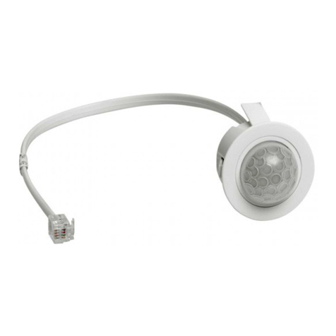
Acuity Controls MSD 7 User manual

INSTRUCTION
SHEET
MSD (PDT) 7
Embedded 360°
Motion Sensor
© 2016 Acuity Brands Lighting Inc., All Rights Reserved.1/ 2 016
COVERAGE PATTERNS
SPECIFICATIONS
PHYSICAL SPECS
SIZE: 1.34”H x 1.18”W x 2.62”D
WEIGHT: 3 oz
MOUNTING: Required Hole Size 1.125”
Material Thickness 0.25”max
COLOR: White
ELECTRICAL SPECS
OPERATING VOLTAGE : 12-24 VDC
CURRENT DRAW: 4 mA
DIMMING LOAD: Sinks < 20mA;
~40 Ballasts / LED drivers (0-10VDC)
ENVIRONMENTAL SPECS
OPERATING TEMP: 32° to 140° F (0° to 60° C)
RELATIVE HUMIDITY: 20 to 90% non-condensing
ROHS COMPLIANT
Lens rotates 15° to
enable adjustment
HIGH VIEW
0 ft
15
0 m
4.6
30 24 18 12 6 0 ft 6 12 18 24 30
9.2 7.4 5.4 3.6 1.8 0 m 1.8 3.6 5.4 7.4 9.2
30
24
18
12
6
0 ft
6
12
18
24
30
9.2
7.4
5.4
3.6
1.8
0 m
1.8
3.6
5.4
7.4
9.2
LOW VIEW
0 ft
9
0 m
2.7
18 15 12 9 6 3 0 ft 3 6 9 12 15 18
5.4 4.6 3.6 2.7 1.8 0.9 0 m 0.9 1.8 2.7 3.6 4.6 5.4
18
15
12
9
6
3
0 ft
3
6
9
12
15
18
5.5
4.6
3.7
2.7
1.8
0.9
0 m
0.9
1.8
2.7
3.7
4.6
5.5
9 FT MOUNTING 15 FT MOUNTING
• Recommended for walking motion detection from mounting heights between 8 ft (2.44 m) and 20 ft (6.10 m)
• Initial detection of walking motion along sensor axes at distances of 2x the mounting height up to 15 ft (4.57 m)
and 1.75x up to 20 ft (6.10 m).
• Provides 12 ft (3.66 m) radial detection of small motion when mounted at 9 ft (2.74 m)
• At the 7.5 ft (2.29 m) hanging height of a typical pendant or suspended mount fixture the sensor provides 10 ft
(3.05 m) radial detection of small motion.
• Initial detection will occur earlier when walking across sensor’s field of view than when walking directly at sensor
WIRING DO NOT WIRE HOT
RED - 12-24 VDC Power Input
VIOLET - LowVoltage Dim Output (0-10 VDC)
BLACK - LowVoltage Common
Note: Do not connect the dimming wires of
multiple sensors in parallel.
0 - 10 VDC
LED DRIVER / BALLAST
DC Power (12-24V)
DIAGRAM 1. INSTALLATION EXAMPLE DIAGRAM 2. ASSEMBLY DETAIL
OPTIONAL SPACER
PAD LOCATION
PRY UP UNDER LIP ON SIDES WITH
ARROWS TO UNSNAP LENS ASSEMBLY
OPTIONAL SPACER
PAD LOCATION
INSTALLATION
• If not pre-installed, locate sensor body so that detector faces down through 1.125”hole in luminaire.
• Align lens assembly legs with holes in sensor body and snap together (max material thickness 0.25”).
• Apply foam spacer pads onto sensor body if needed to ensure snug fit with fixture.
• Assembly rotates 15° to enable coverage pattern adjustment after installation.
• To unsnap lens assembly, pry up under lip at spots on lens assembly denoted by arrows.
5-year limited warranty. Full warranty terms located at:
www.acuitybrands.com/CustomerResources/Terms_and_conditions.aspx
Note: Specifications subject to change without notice.
Actual performance may differ as a result of end-user environment and application.

MSD (PDT) 7 INSTRUCTION SHEET PAG E 2
www.acuitycontrols.com 800-535-2465 911-00043-026 SSI_2626
DETAILED FUNCTION TABLES (CONT.)
110 fc 440 fc 7200 fc
220 fc 550 fc 8Disable
330 fc 6100 fc 10 0 fc*
10 min* 330 min 560 min
215 min 445 min
11 fc 44 fc 77 fc 10 0 fc
22 fc 55 fc* 88 fc
33 fc 64 fc 99 fc
1x/1 4x/4* 7x/7 10 x/10
2x/2 5x/5 8x/8
3x/3 6x/6 9x/9
1Decrease 1 fc 4Increase 1 fc
1Normal** 4Dim Only (No Off)*
5 Ten’s Digit of Set-Point
The ten’s digit of the target light level that is to be maintained by the device (in foot-candles)
10 Minimum On Time
The length of time required for lamps to be on in order to prevent all short cycling that shortens lamp
life. If occupancy time delay expires prior to minimum on time being satisfied, the lamps will remain
on until time has been met.
6 One’s Digit of Set-Point
The one’s digit of the target light level that is to be maintained by the device (in foot-candles)
7 Sunlight Discount Factor
Value used to improve the tracking accuracy of a photocell during periods of high daylight.
Decreasing the value will lower the controlled level of the lights
8 Incremental Set-Point Adjustment
Alters the target light level that is to be maintained by the device (in foot-candles)
11 Photocell Mode
Indicates a photocell sensor’s method of operation. One mode enables the sensor to turn the lights
both on and off, while the other mode can only inhibit the lights from turning on. For dimming
sensors, this mode determines whether lighting will switch completely off or stop at the full dim level.
DETAILED FUNCTION TABLES
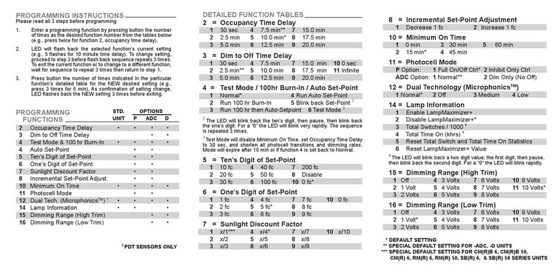
PROGRAMMING INSTRUCTIONS
PROGRAMMING FUNCTIONS
PLEASE READ ALL 3 STEPS BEFORE PROGRAMMING
1. Enter a programming function by pressing button the number of times as the desired function number
from the tables below (e.g., press twice for function 2, occupancy time delay).
2. LED will flash back the selected function’s current setting (e.g., 4 flashes for 7.5 minute time delay).
To change setting, proceed to step 3 before flash back sequence repeats 3 times.To exit the current
function or to change to a different function, wait for sequence to repeat 3 times then return to step 1.
3. Press button the number of times indicated in the particular function’s detailed table for the NEW
desired setting (e.g., press 3 times for 5 min). As confirmation of setting change, LED flashes back the
NEW setting 3 times before exiting.
STD. UNIT ADC
2Occupancy Time Delay • •
3 Dim to Off Time Delay • •
4 Test Mode & 100 hr Burn-In • •
4 Auto Set-Point •
5 Ten’s Digit of Set-Point •
6 One’s Digit of Set-Point •
7 Sunlight Discount Factor •
8 Incremental Set-Point Adjust. •
10 Minimum On Time • •
11 Photocell Mode •
12 Dual Tech. (Microphonics™) • •
15 Dimming Range (High Trim) • •
16 Dimming Range (LowTrim) • •
21 Photocell Transition Off Time •
22 Photocell Transition On Time •
130 sec 47.5 min* 715.0 min
22.5 min 510.0 min 817.5 min
35.0 min 612.5 min 920.0 min
130 sec 47.5 min 715.0 min 10 0 sec
22.5 min** 510.0 min 817.5 min 11 Infinite*
35.0 min 612.5 min 920.0 min
1Normal* 4Run Auto Set-Point
2Run 100 hr Burn-In 5Blink back Set-Point 1
3Run 100 hr then Auto-Setpoint 6Test Mode 2
2 Occupancy Time Delay
The length of time an occupancy sensor will keep the lights on and at full bright after it last detects
occupancy (assuming minimum on time has been met)
3 Dim to Off Time Delay
An extended length of time after the occupancy time delay has expired that a sensor will first reduce
lighting to the low dimming range setting before turning completely off
4 Test Mode & 100 hr Burn-In/ Auto Set-Point
Test Mode
Disables Minimum On Time, sets Occupancy Time Delay to 30 sec, and shortens all photocell
transition and dimming rates. Mode will expire after 10 min or if function 4 is set back to Normal.
100 Hour Burn-In
Overrides relay on and/or dimming output to full bright (typically for lamp seasoning)
Auto Set-Point
Photocell calibration procedure for detecting optimum lighting control level
1 The LED will blink back the ten’s digit, then pause, then blink back the one’s digit. For a“0”the LED will blink very rapidly.
The sequence is repeated 3 times.
2 Test Mode will disable Minimum On Time, set Occupancy Time Delay to 30 sec, and shorten all photocell transitions and
dimming rates. Mode will expire after 10 min or if function 4 is set back to Normal.
* Default Setting
** Special Default Setting for -EZ Units
145 sec 35 min 515 min 725 min
22 min 410 min* 620 min
145 sec* 35 min 515 min 725 min
22 min 410 min 620 min
1Off / 0 Volt 53 Volts 97 Volts 13 10 Volts*
21 Volt 64 Volts 10 8 Volts
31.5 Volts 75 Volts 11 9 Volts
42 Volts 86 Volts 12 9.1 Volts**
1Off / 0 Volt 53 Volts 97 Volts 13 10 Volts
21 Volt* 64 Volts 10 8 Volts
31.5 Volts** 75 Volts 11 9 Volts
42 Volts 86 Volts 12 9.1 Volts
15 Dimming Range (High Trim)
The maximum output level (0-10VDC) of a sensor with a dimming output
16 Dimming Range (Low Trim)
The minimum output level (0-10VDC) of a sensor with a dimming output
21 Photocell Transition Off Time
The time period after the photocell measures a light level above the set-point (plus the deadband)
that it will turn lights off (or dim them to min level)
21 Photocell Transition On Time
The time period after the photocell measures a light level below the set-point that it will turn lights on
1Normal* 2Off 3Medium 4Low
12 Dual Technology (Microphonics™)3
A second method of occupancy detection that allows the sensor to hear occupants
3 Applicable for -PDT units only.
This manual suits for next models
1
Table of contents
Other Acuity Controls Accessories manuals
