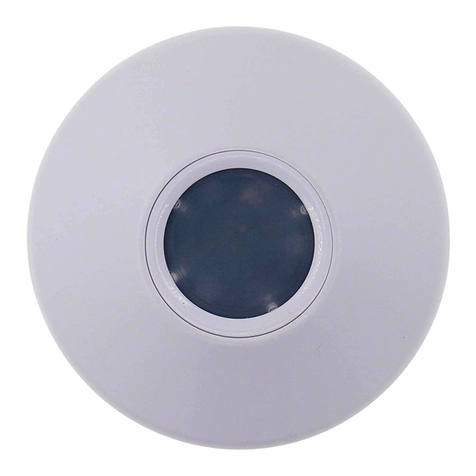
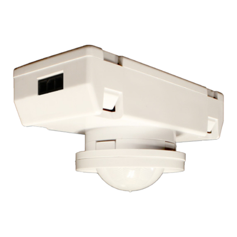
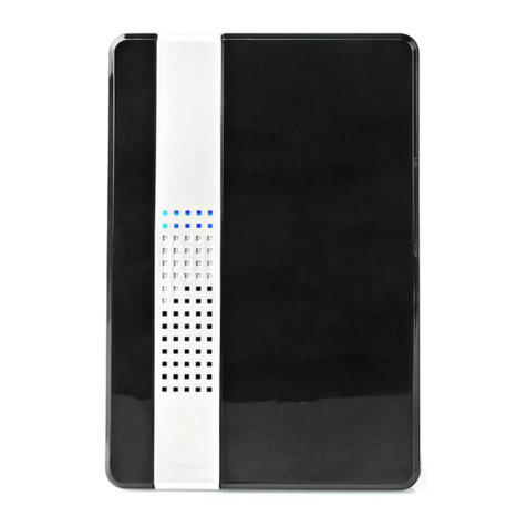
Acuity Controls nCM RJB Series User manual

SPECIFICATIONS
PHYSICAL
SIZE: 4.55”Dia. (11.56 cm)
1.55”Deep (3.94 cm)
WEIGHT: 6 oz
MOUNTING:
CeilingTile / Sheetrock Surface
3.5”Octagon Box
Single Gang Handy Box
COLOR: MatteWhite
nLIGHT NETWORK CONNECTION:
2 RJ-45 Ports (via an included RJ-45 splitter)
WIRES / CABLES:
(1) CAT5e patch cable, 1ft (factory installed)
(2) 20 AWG wires (-AR option only)
1 of 2
CEILING / SURFACE MOUNT • REAR RJ-45 PORT
PASSIVE INFRARED (PIR) or DUAL TECH (PDT)
nCM 9 xx RJB
nCM PDT 9 xx RJB
nCM 10 xx RJB
nCM PDT 10 xx RJB
nCM 6 xx RJB
ELECTRICAL
nLIGHT BUS POWER CONSUMPTION: ~3 mA
RELAY RATING (-AR option only):
1A @ 24VAC/VDC (resistive only)
ENVIRONMENTAL & OTHER
OPERATING TEMP
Standard: 14º to 160º F (-10º to 71º C)
LT Option (PIR): -40º to 160º F (-40º to 71º C)
LT Option (PDT): -4º to 160º F (-20º to 71º C)
RELATIVE HUMIDITY
Standard: 20 to 75% non-condensing
LT Option: 20 to 90% non-condensing
SILICONE FREE, ROHS COMPLIANT
TITLE 24 SYSTEM COMPONENT
ASSEMBLED in U.S.A.
COVERAGE PATTERNS
HIGH MOUNT 360º (Model # nCM 6)
•Best choice for 15 to 45 ft (4.57 to 13.72 m)
mounting heights
• 15 to 20 ft (4.57 to 6.10 m) radial coverage
overlaps area lit by a typical high bay xture
• Excellent detection of large motion (e.g.
walking) up to 35 ft (10.76 m)
• Excellentdetectionofextralargemotion(e.g.
forklifts) up to a 45 ft (13.72 m)
30 20 10 0 ft 10 20 30
9.1 6 3 0 m 3 6 9.1
0 ft
15
30
45
0 m
4.6
9.1
13.7
LOW VIEW HIGH VIEW
0 ft
15
0 m
4.6
20 10 0 ft 10 20
6 3 0 m 3 6
30 20 10 0 ft 10 20 30
9.1 6 3 0 m 3 6 9.1
0 ft
15
30
45
0 m
4.6
9.1
13.7
LOW VIEW HIGH VIEW
0 ft
15
0 m
4.6
20 10 0 ft 10 20
6 3 0 m 3 6
•Best choice for large motion detection (e.g.
walking)
• 360ºconicalshapedpattern
• Provides ~24 ft (7.32 m) radial coverage
(~2000 ft2) when mounted at 9 ft (2.74 m)
• 7to15ft(2.13to4.57m)mountingheights
provide 16 to 36 ft (4.88 to 10.97 m) radial
coverage
• Detection range improves when walking
across beams compared to into beams
LARGE MOTION 360º (Model # nCM 10/nCM PDT 101)
0 ft
9
0 m
2.7
28 21 14 7 0 ft 7 14 21 28
8.5 6.4 4.3 2.1 0 m 2.1 4.3 6.4 8.5
SIDE VIEW TOP VIEW
28
14
0 ft
14
28
8.5
4.3
0 m
4.3
8.5
1 Sensors with Microphonics™ provides overlapping detection of human activity over the complete PIR coverage
area. Advanced ltering is also utilized to prevent non-occupant noises from keeping the lights on.
•Best choice for small motion (e.g. hand
movements) detection
• 360ºconicalshapedpattern
• Provides12ft(3.66m)radialcoverage(~500
ft2) when mounted to standard 9 ft (2.74 m)
ceiling
• 8to15ft(2.44to4.57m)mountingheights
provide 10 to 20 ft (3.05 to 6.10 m) radial
coverage
SMALL MOTION 360º (Model # nCM 9/nCM PDT 91)
12 6 0 ft 6 12
3.7 1.8 0 m 1.8 3.7
SIDE VIEW
0 ft
9
0 m
2.7
TOP VIEW
12
6
0 ft
6
12
3.7
1.8
0 m
1.8
3.7
1 Sensors with Microphonics™ provides overlapping detection of human activity over the complete PIR coverage
area. Advanced ltering is also utilized to prevent non-occupant noises from keeping the lights on.
nCM xx RJB
FAMILY INSTRUCTIONS
MODEL # OPTION SUFFIXES
PDT = DualTechnology (Microphonics) Detection
6, 9,10 = Lens/Coverage Pattern
ADCX = Automatic Dimming Control
AR = LowVoltage Aux. Relay
2P = Dual Time Delay
LT = Low Temp / High Humidity
Acuity Controls | 900 Northrop Road,Wallingford, CT 06492 PHONE: (800)-727-7483 nLightcontrols.com ©2015 Acuity Brands Lighting, Inc. All rights reserved. 10/26/20

2 of 2
nCM xx RJB
FAMILY INSTRUCTIONS
WARRANTY
5-year limited warranty. Full warranty terms located at:
www.acuitybrands.com/CustomerResources/Terms_and_conditions.aspx
Note: Specications subject to change without notice. Actual performance may dier as a result of end-user environment and application.
The following instructions are for mounting sensor directly to a ceiling tile or
sheetrock surface. Sensor’s mounting holes also align with standard round xture or
single gang handy box (screws not provided).
1. Using template included with unit, mark spots on ceiling tile/sheetrock for cable
hole and mounting anchors/screws
2. Drill 1/2”hole through ceiling surface at location indicated on template
3. Insert provided anchors into ceiling surface at locations indicated on template
4. Remove provided RJ-45 splitter from sensor’s attached CAT5e cable and
thread cable (and low voltage wires if -AR option included) through hole from
underside
5. Mount sensor to anchors using two screws provided
6. Reattach RJ45 splitter device (model CAT5 Y) above ceiling to cable from sensor
(see diagram on right)
7. Interconnect CAT-5e cables to/from rest of nLight zone to RJ45 splitter
8. Once power is received via CAT-5e connection, all devices in zone will
automatically begin functioning together according to each device’s defaults
9. Install decorative sensor lid by rotating clockwise
10. Refer to included instruction card for default settings and directions on push-
button programming.
INSTALLATION / WIRING
Sheet#: TNG-139-001
CAT-5e
BRN
BRN
CA
T-5e Splitter
CAT-5e CAT-5e
- AR option
(contact closure)
to/from nLight
Zone
• To reduce the risk of death, personal injury or property damage from re, electric shock, falling parts, cuts/abrasions, and other
hazards please read all warnings and instructions included with and on the xture box and all xture labels.
• Before installing, servicing, or performing routine maintenance upon this equipment, follow these general precautions.
• Installation and service should be performed by a qualied licensed electrician.
• Maintenance should be performed by qualied person(s) familiar with the products’ construction and operation and any haz-
ards involved. Regular maintenance programs are recommended.
READ AND FOLLOW ALL SAFETY INSTRUCTIONS!
SAVE THESE INSTRUCTIONS AND DELIVER TO OWNER AFTER INSTALLATION
•DO NOT INSTALL DAMAGED PRODUCT! This product has been properly packed so that no parts should have been damaged
during transit. Inspect to conrm. Any part damaged or broken during or after assembly should be replaced.
CAUTION: RISK OF PRODUCT DAMAGE
√ Electrostatic Discharge (ESD): ESD can damage product(s).
Personal grounding equipment should be worn
during all installation or servicing of the unit.
√ Do not touch individual electrical components, as this can cause
ESD and aect product performance.
√ Do not stretch or use cable sets that are too short or are of insuf-
cient length.
√ Do not tamper with contacts.
√ Do not modify the product.
√ Do not change or alter internal wiring or installation circuitry.
√ Do not use product for anything other than its intended use.
WARNING - RISK OF BURN or FIRE
√ Do not exceed maximum wattage, ratings, or published operation conditions
of product.
√ Do not overload.
√ Follow all manufacturer’s warnings, recommendations and restrictions to
ensure proper operation of product.
CAUTION - RISK OF INJURY
√ Wear gloves and safety glasses at all times when installing, servicing or performing
maintenance.
WARNING - RISK OF ELECTRIC SHOCK
√ Disconnect or turn o power before installation or servicing.
√ Verify that supply voltage is correct by comparing it with the product
information.
√ Make all electrical and grounded connections in accordance with the National
Electrical Code (NEC) and any applicable local code requirements.
√ All wiring connections should be capped with UL approved recognized wire
connectors.
√ All unused connector openings must be capped.
Note: T568B pin/pair assignment is recommended for all CAT-5e cables. Sensor
power is provided via a CAT-5e connection to an nLight power pack/supply, nLight
enabled digital luminaire, or nLight Bridge.
Acuity Controls | 900 Northrop Road,Wallingford, CT 06492 PHONE: (800)-727-7483 nLightcontrols.com ©2015 Acuity Brands Lighting, Inc. All rights reserved. 10/26/20

Acuity Controls | 900 Northrop Road,Wallingford, CT 06492 PHONE: (800)-727-7483 nLightcontrols.com ©2015 Acuity Brands Lighting, Inc. All rights reserved. 10/26/20 2 of 2
nCM xx RJB
FAMILY INSTRUCTIONS
A LEVEL PUSH-BUTTONFUNCTIONS
1
POLE SELECTION / BUTTON MODE2
For 2-Pole devices: functions 2 ,5, 6, and 8 can be programmed differently for each pole. The selections
for the Pole Selection function determine which pole’s settings are to be modified by subsequent
programming. Button Mode overrides a device and enables its push-button to toggle the device’s internal
relay(s) or dim level
1
1st Pole13 Copy Pole 1’s settings to Pole 2 5 Enable ButtonMode
2
2nd Pole 4 Disable ButtonMode
2
TIME DELAY
The length of time an occupancy sensor will keep the lights on after it last detects occupancy
STANDARD
1 30 sec 3 5.0 min 5 10.0 min1 7 15.0 min 9 20.0 min
2 2.5 min 4 7.5 min 6 12.5 min 8 17.5 min
EXTENDED
1
30 sec 3 30 min 5 60 min 7 90 min 9 120min
2
15 min 4 45 min 6 75 min 8 105 min
3
IDLE TIME UNTIL DIM
The length of time after last detected occupancy that a sensor will reduce lighting to unoccupied dim level.
STANDARD
3 30 sec 3 5.0 min 5 10.0 min 7 15.0 min 9 20.0 min
4 2.5 min 4 7.5 min1 6 12.5 min 8 17.5 min 10 Disable
EXTENDED
1
30 sec 3 30 min 5 60 min 7 90 min 9 120 min
2
15 min 4 45 min 6 75 min 8 105 min 10 Disable
3
START TO HIGH
Lights go to full bright for 20 minutes upon initial powerup
5 Disabled1 2 Enabled
4
AUTO SET-POINT / 100 HOUR BURN-IN
100 HOUR BURN-IN: Overrides relays on (typically for lampseasoning)
AUTO SET-POINT: Photocell calibration procedure for detecting optimum lighting control level
1
Disabled1 3 Enabled then run Auto-Setpoint 5 Blink backSet-Point3
2
Enabled 4 Run Auto Set-Point
1 DEFAULT SETTING 2 REQUIRES PRESS & HOLD METHOD
5
TEN’S DIGIT OF SET-POINT
The ten’s digit of the target light level that is to be maintained by the device (in foot-candles)
1 10 fc 3 30 fc 5 50 fc 7 200 fc 10 0 fc1
2 20 fc 4 40 fc 6 100 fc 8 Disable
6
ONE’S DIGIT OF SET-POINT
The one’s digit of the target light level that is to be maintained by the device (infoot-candles)
1 1 fc 3 3 fc 5 5 fc17 7 fc 9 9 fc
2 2 fc 4 4 fc 6 6 fc 8 8 fc 10 0 fc
7
SUNLIGHT DISCOUNT FACTOR
Value used to improve the tracking accuracy of a photocell during periods of high daylight. Decreasing the
value will lower the controlled level of thelights
1 x/11 3 x/3 5 x/5 7 x/7 9 x/9
2 x/2 4 x/4 6 x/6 8 x/8 10x/10
8
INCREMENTAL SET-POINTADJUSTMENT
Alters the target light level that is to be maintained by the device (infoot-candles)
1 Decrease 1 fc 2 Increase 1 fc
9
RESTORE FACTORY DEFAULTS2
2 Restore Defaults1 Maintain Current
10
TIME DELAY SCHEME2
Selects the range of time delay values available for use by function 2, TimeDelay.
POLE 1 POLE 2 POLE 1 POLE 2
1
Standard Standard
2
Standard Extended
3 Extended Standard
4 Extended Extended
11
PHOTOCELL MODE2
Indicates a photocell sensors method of operation. One mode enables the sensor to turn the lights both
on and off while the other mode can only inhibit (prevent) the lights from turningon
1 Full On/Off Control12 Inhibit Only Control
3 The LEDwill blink back the ten’s digit, then pause, then blink back the one’s digit. For a “0” the LED will blink
very rapidly. The sequence is repeated 3times.
11
DUAL ZONE PHOTOCELL MODE2 (DZ ModelsOnly)
Indicates a Dual Zone photocell sensor’s method of operation
STEPPED DIMMING (DUO) MODE :
Mode where the appropriate on/off combination of
the two associated relays is maintained in order to
always meet the photocell set-pointrequirements
STEPPED DIMMING (DUO) MODE –
NEVER OFF:
Mode where the appropriate on/off combination
of the two associated relays (except both off) is
maintained in order to always meet the photocell
set-point requirements.
DUAL ZONE OFFSET MODE : Mode where Zone
2’s set-point is a selected percentage higher than
Zones 1’s set-point
DUAL ZONE FAN MODE : Mode where Zone 2’s
photocell control is disabled
1 Duo1 2 Duo-Never Off 3 Offset 4 Fan Mode 5 Inhibit
12
DUAL TECHNOLOGY(MICROPHONICSTM)
A second method of occupancy detection that allows the sensor to hearoccupants
1 Normal1 2 Off 3 Medium 4 Low
13
MICROPHONE GRACE PERIOD TIME2
The time period after lights are automatically turned off that they can be voice reactivated
1 0 3 20 5 40 7 60
2 1014 30 6 50
15
PHOTOCELL DIMMING RANGE (HIGH)
The maximum output level (0-10 VDC) up to which an automatic dimming photocell will control
1 Off 3 2 Volts 5 4 Volts 7 6 Volts 9 8 Volts 1110Volts1
2 1 Volt 4 3 Volts 6 5 Volts 8 7 Volts 109 Volts
16
PHOTOCELL DIMMING RANGE (LOW)
The minimum output level (0-10 VDC) down to which an automatic dimming photocell will control
1
Off13 2 Volts 5 4 Volts 7 6 Volts 9 8 Volts 1110 Volts
2
1 Volt 4 3 Volts 6 5 Volts 8 7 Volts 10 9 Volts
17
DUAL ZONE OFFSET
Fixed voltage increase of Zone 2’s dimming output from Zone 1’s dimming output (Dual Zone photocell
applications only) 21 10 Volts
1
-10 Volts 5 -6 Volts 9 -2 Volts 13 2 Volts1 176 Volts
2
-9 Volts 6 -5 Volts 10-1 Volt 14 3 Volts 18 7Volts
3
-8 Volts 7 -4 Volts 11 0 Volts 15 4 Volts 198Volts
4
-7 Volts 8 -3 Volts 12 1 Volt 16 4 Volts 20 9Volts
18
DUAL ZONE OFF POINT2
Zone 2’s set-point as a percentage of Zones 1’s set-point (Dual Zone photocell applications only)
1 110% 3 130% 5 150%1 7 170% 9 190%
2 120% 4 140% 6 160% 8 180% 10 200%
19
DIMMING RATE
The speed at which automatic changes to the light leveloccur 5 7 sec1 700 sec 2 350 sec 3 70 sec1 4 35 sec
20
LED2
Indicates the behavior of a device’s LED
7 Normal1 2 Inhibited
21
PHOTOCELL TRANSITION OFF TIME
The time period for which a photocell must measure a light level above the set-point before it will turn the
lights off
1
45 sec 3 5 min15 15 min 7 25 min
2
2 min 4 10 min3 6 20 min
22
PHOTOCELL TRANSITION ON TIME2
The time period for which a photocell mustmeasure a light level below the set-pointbefore itwill initiate the
lights on
1
45 sec1 3 5 min
2
2 min 4 10 min 5 15 min 7 25 min
6 20 min
23
OCCUPIED BRIGHT LEVEL
The output level (0-10 VDC) that a dimming sensor sets the light to when occupancy is detected (not
applicable if photocell isenabled)
1
1 Volt 3 3 Volts 5 5 Volts 7 7 Volts 9 9 Volts
2
2 Volts 4 4 Volts 6 6 Volts 8 8 Volts 10 10Volts1
24
UNOCCUPIED DIM LEVEL
The output level (0-10 VDC) a dimming sensor sets the lights after the idle time until dim timer expires
1
1 Volt1 3 3 Volts 5 5 Volts 7 7 Volts 9 9 Volts
2
2 Volts 4 4 Volts 6 6 Volts 8 8 Volts 10 10 Volts
26
FOLLOW PHOTOCELL MODE
3 Enabled Both Positive andNegative
Instructs how a device’s dimming output reacts relative to a dimming photocell
1
Disabled
1
2
Enabled Negative Only
27
SWEEP EXIT TIME
The time period before a sweep isexecuted
1 0 sec 3 30 sec 5 1 min 7 3 min 9 5 min
2 15 sec14 45 sec 6 2 min 8 4min
28
SWEEP GRACE PERIOD
The remaining time delay after a sweep isexecuted
1
0 sec 3 10 sec 5 30sec
2
5 sec1 4 15 sec 6 1min
1 DEFAULT SETTING 2 REQUIRES PRESS & HOLD METHOD
This manual suits for next models
5
Other Acuity Controls Accessories manuals
