CKD Rapiflow FSM2-N Series User manual

D2-180341-A
INSTRUCTION MANUAL
SMALL SIZE FLOW SENSOR
RAPIFLOW®
FSM2-[ ]N series
(Integrated needle valve type)
●Read this instruction manual carefully before using this
product, particularly the section describing safety.
●Retain this instruction manual with the product for further
consultation whenever necessary.
2nd EDITION
Discontinue

Warning / cautions to secure safety
●Safety cautions are ranked by the safety cautions as
[danger] [warning] [caution] in this section.
●Working fluid, Working environment
●Installation
●Wiring
●Usage & maintenance
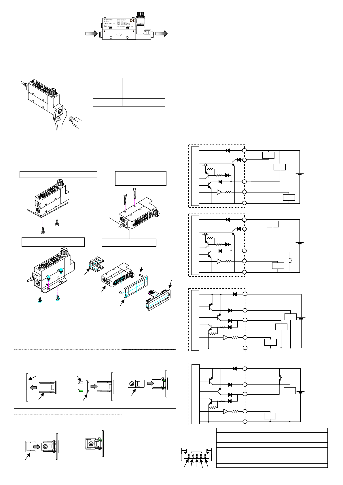
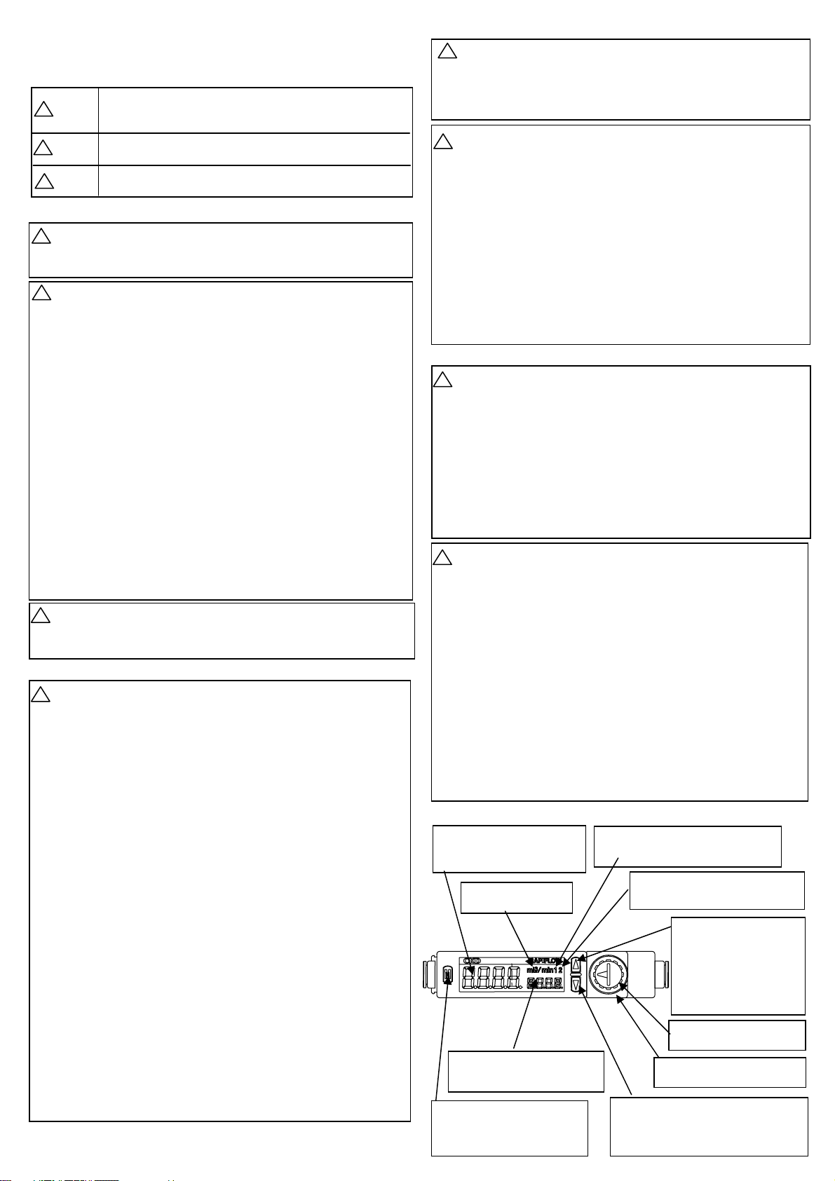
[1]Names and Functions of Each Parts
■The flow rate of this product is measured by mass flow not
depended with temperature and pressure. Unit is L/min where
mass flow is converted to volumetric flow at 20 °C and 1
atmospheric pressure (101kPa).
■The product can not be used as a business mater. Not conformed
to the Measurement Law, do not use the product for the
commercial purpose. Use the product as an industrial sensor.
■Do not use the product with other than applicable working fluids,
or the accuracy can not be guaranteed. Do not use for corrosive
and flammable gases.
■Install a filter, an air dryer and an oil mist filter (micro alescer) onto
the primary side (upstream) of the sensor since the compressed
air from the compressor contains drain (water, oil oxide and
foreign material, etc.)
■When using this product with adsorption verification, etc., always
install an air filter onto the upstream of suction side to prevent
suction of foreign materials.
■Do not use the product in an environment containing corrosive
gas such as salphur dioxide, etc.
■Use the product within the ambient and fluid temperature ranges
0 to 50 °C. Even in the specified temperature range, do not use
the product where ambient and fluid temperatures will change
suddenly, and form dew condensations.
■Use the product in accordance with specifications. If used out of
the maximum working pressure and working flow range, the
product may result in failures.
■The protective structure of this product is equivalent to IP40. Do
not install the product where moisture, salt, dust or swarf is
contained, or where pressurized, or depressurized, neither.
When a dangerous situation may occur, or when there is high
urgency to a warning leading to fatal or serious injuries, if handling
is mistaken.
When a dangerous situation may occur if handling is mistaken,
leading to fatal or serious injuries.
When a dangerous situation may occur if handling is mistaken,
leading to minor injuries or physical damages.
Danger
!
■A flammable fluid must not be used.
■Do not use the product in flammable gas environment. Since
explosion-protection is not taken, explosion or fire may be
caused.
■Arrange piping so that the flow direction agrees with the direction
of the arrow indicated on the sensor body.
■When piping a sensor, do not apply excessive screw-in and load
torques to the port.
■Flash the pipe to remove foreign substances and swarf, etc., in
inside of pipe before piping.
■When piping, apply a spanner on the metal section not to apply
forces onto the resin section.
■When piping, care must be taken that sealing tape and adhesive
must not enter into the inside.
■When using the metal body with OUT side released, always
connect a joint, or the port filter may be removed.
■If a push-in joint is used, the tube must be inserted certainly. Pulls
the tube to check that the tube not be come out.
■Make sure that the joint and tube are not twisted or pulled, and
that moment load is not applied.
■The display part uses the LCD. The display becomes difficult to
see for the view angle.
■This product can be installed with any attitude; vertical, horizontal,
right or left.
■This product cannot be used as a stop valve with zero leakage.
Slight leakage is allowed in product specifications.
■Dust generation inside the paths of the needle valve is not zero.
Install a final clean filter in circuits where dust generation causes
problems.
■When you install the panel, please install this product after piping
etc.
■Check that lock nuts are not loose. Actuator speed cannot be
controlled if the lock nut is loose.
■A stopper mechanism is provided, but damage could result if the
needle is turned too far.
■Power supply voltage and outputs must be used with the
specified voltage. Applying the voltage more than specified
voltage may cause malfunction, damage of sensor, electric
shock or fire.
Do not apply load more than the rated output. Damage or fire of
the output may be caused.
■For wiring, stop control unit/machinery and equipment, and turn
off the power supply.
■This product and wiring must be installed as far away as possible
from noise source such as strong electric line, etc. Take other
countermeasures for a surge on the power supply line.
■Do not short-circuit a load, or causing damage or burn.
■Line color must be checked when wiring. Check the wiring color
with handling precaution, since improper wire connection may
result in damage, failure or malfunction of the sensor.
■Use DC safety power supply thoroughly insulated from the AC
primary side for a power supply for the metal body (stainless
steel and aluminum bodies) type, while connecting either + or -
side on the power supply to F.G.
■After the connectors are inserted, lay the connector covers over
the connectors.
■Make sure that stress by forcible bend of pulling is not applies
directly to the sensor cable joint.
■Output accuracy is affected by self exoergics caused by
energizing other than temperature characteristics. When using,
stand-by time (5 minutes and over after energizing) must be
provided.
■For self-diagnosis, this product does not conduct flow rate
detecting switch operation for proximate 4 seconds immediately
after energized. Make a control circuit and programs to ignore
signals for approximate 2 seconds after energized.
■This product cannot be used as a stop valve with zero leakage.
Slight leakage is allowed in product specifications.
■Dust generation inside the paths of the needle valve is not zero.
Install a final clean filter in circuits where dust generation causes
problems.
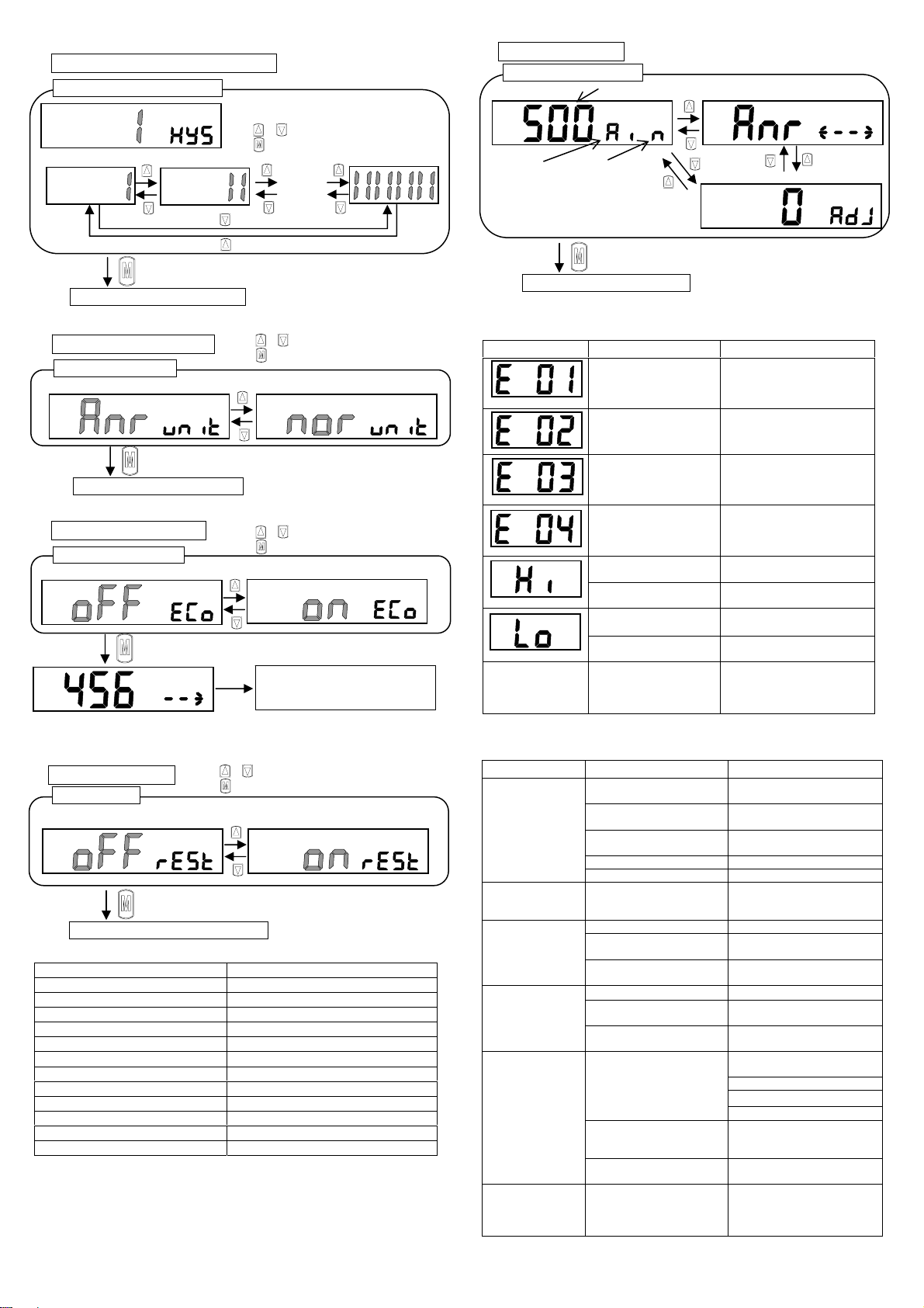
■When changing set-points of the output, stop the equip-ment,
then change the set-points, or an accident may occur.
■Disassembly and modification must not be done or causing a
failure.
■When an error occurs during operation, turn off power supply
immediately, and terminate the operation, and contact to the
sales office.
■The material of case is resin. Solvent/alcohol/cleaner, etc., must
not be used to remove contamination, etc., or causing a resin to
be corroded. Wipe weakened neutral detergent with tightly
squeezed waste cloth, etc.
■When out of flow rate range, analog output will be provided. [Hi]
or [Lo] will be displayed. However, accuracy is not guaranteed.
■Do not push the display part., or causing damage.
■Do not turn the knob too forcibly when fully closing or opening
the knob (within 0.05N-m). As well, do not pinch the lock nut
when adjusting the needle. Otherwise the needle will gall or be
broken.
Warning
!
Caution
!
Danger
!
Warning
!
Caution
!
Caution
!
Danger
!
Caution
!
Warning
!
Caution
!
Mode key
■Press to enter each setting mode
■Press to advance setting mode
■Press to return to flow rate display
■Press to cancel peak hold operation
Up key
■When flow rate is displayed =
Displays the CH1 data
■During peak hold operation =
Displays the maximum value
■When selecting a mode =
Sets the mode
■When setting each data =
Increases the value, etc.
Down key
■When flow rate is displayed = Displays the CH2 data
■During peak hold operation =Displays the maximum
value
■When setting each data =Increases the value, etc.
Main display (Green/Red)
■Displays flow rate, various switch
settings.
■Indication color is selectable.
Sub-display (Green/Red)
●Displays flow direction, machine status.
●Indication color is selectable.
Unit display (Green)
■Displays flow rate unit
Switch output indicator (CH1)
■Lights when switch output (CH1) turns on.
■Blinks when over current protection is operating
Switch output indicator (CH2)
■Lights when switch output (CH2) turns on.
■Blinks when over current protection is operating
Knob
■Flowing quantity is adjusted.
Lock nut
■When the knob is fixed, it uses it.
-1-
Discontinue

[2] Installation
■Arrange piping so that the flow
direction agrees with the direction
of the arrow indicated on the
sensor body.
■Flash the pipe to remove foreign substances and swarf, etc., in inside of
pipe before piping.
■When piping a sensor, do not apply excessive screw-in and load torques to the
port.
When piping, apply a spanner on the metal section not to apply forces
onto the resin section.
■When piping, care must be taken that sealing tape and adhesive must
not enter into the inside.
■If a push-in joint is used, the tube must be inserted certainly. Pulls the
tube to check that the tube not be come out.
■This product can be installed with any attitude; vertical, horizontal, right
or left.
The tightening torque for screws should be 0.5N・m.
<How to panel mount>
[3] Piping
■Power supply voltage and outputs must be used with the specified
voltage. Applying the voltage more than specified voltage may cause
malfunction, damage of sensor, electric shock or fire.
Do not apply load more than the rated output. Damage or fire of the
output may be caused.
■For wiring, stop control unit/machinery and equipment, and turn off the
power supply.
■This product and wiring must be installed as far away as possible from noise
source such as strong electric line, etc. Take other countermeasures for a
surge on the power supply line.
■Do not short-circuit a load, or causing damage or burn.
■Line color must be checked when wiring. Check the wiring color with handling
precaution, since improper wire connection may result in damage, failure or
malfunction of the sensor.
■Use DC safety power supply thoroughly insulated from the AC primary side for
a power supply for the metal body (stainless steel and aluminum bodies) type,
while connecting either + or - side on the power supply to F.G.
■After the connectors are inserted, lay the connector covers over the
connectors. Make sure that stress by forcible bend of pulling is not applies
directly to the sensor cable joint.
●Example of internal circuit and load connection
NPN output Model no.: FSM2 -N[ ]-[ ]
<CH2 function selected switch output>
<CH2 function selected external input>
PNP output Model no.: FSM2 -P[ ]-[ ]
<CH2 function selected switch output>
<CH2 function selected external input>
[1] [2] [3]
The panel bessel is inserted
from the front side of the
panel.
The panel Bessel is inserted
from the back side of the
panel, and holding with the
screw.
The separation indicator is
inserted from the back side of
the panel.
[4] [5]
The panel holder is inserted
from the back side of the
panel.
The panel holder is
pushed until the sensor is
firmly fixed, and connector is
connected.
Note:
・Please do the piping work
before it works of the panel
mount, and please do not add
the stress to parts of the
panel mount.
・Please fix by the tightening
torque of 0.06N・m when
you fix the panel bessel
suppression.
Set screw Tightening torque
N・m
Rc1/8 3~5
Rc1/4 6~8
Bracket (separate sales)
Model no. : FSM2-LB1
Port size: Push-in joint φ4、6、8、10
Rc1/8、Rc1/4
Main circuit
Load
Load
Load
Brown (Power supply +)
Gra
y
(
Analo
g
out
p
ut
)
Black (CH1)
Switch out
p
ut 1
White (CH2)
Switch out
p
ut 2
Blue
(
Power su
pp
l
y
-
)
+
-
2
3
4
5
1
Main circuit
Load
Load
White (CH2)
External in
p
u
t
+
-
2
3
4
5
1 Brown (Power supply +)
Black (CH1)
Switch out
p
ut 1
Gray (Analog output)
Pin No. Line color Content
[1] Brown Power supply (DC 12 to 24V, DC 24V)
[2] Black CH1(Switch output 1: max50mA)
[3] White
CH2(Switch output 2: max50mA or External input)
[4] Gray
Analog voltage output : DC 1 to 5V
Connected load impedance 50kΩand over)
Analog current output : DC 4 to 20mA
Connected load impedance 300Ωor less)
[5] Blue 0V (GND)
※Analog output voltage output type R:about1kΩ
Current output type R:about100Ω
[1]
[
2
]
[3] [4] [5]
(FSM2 side)
Vertical mount(with bottom thread) Horizontal mount
(with through hole)
Bracket mount (with bracket)
Main circuit
Load
Load
Load
Brown (Power supply +)
Gray (Analog output)
+
-
Black (CH1)
Switch out
p
ut 1
White (CH2)
Switch output 2
2
3
4
5
1
Blue (Power supply -)
Panel mount
Panel mount kit Model no.
:FSM2-KHS-N
Panel bessel suppression
Screw
Panel
Panel bessel
Sensor
Panel holder
Main circuit
Load
Load
Brown (Power supply +)
Gray (Analog output)
+
-
Black (CH1)
Switch out
p
ut 1
White (CH2)
External input
2
3
4
5
1
Blue (Power supply -)
Panel bessel
Panel bessel suppression
Scre
w
Panel holder
Sensor
-2-
R※
R※
R※
Blue
(
Power su
pp
l
y
-
)
R※
Discontinue

[4] Function
<Normal mode>
Item Description
Flow rate display Instantaneous flow rate is displayed.
Integrating function Integrated flow rate is displayed.
Peak hold
function
Maximum and minimum flow rate values during the specified
period can be read.
Set-point
verification
Switch data (set-point value and operation mode) are
displayed to check.
Key lock Setting changes are disabled to prevent incorrect operations.
Error display
function
The error state is displayed.
<Standard setting mode>
Item Description
Switch output Having 2 pieces of switch output, 7 operation patterns and stop
of operation can be set.
Forcible output
function
Switch output is turned on forcibly to check wiring connection
and initial operation of input unit.
0 point adjustment Deviation of the display from o is corrected.
<Detailed setting mode>
Item Description
Flow direction
selection
Only bi-directional type, flow direction can be switched.
CH2 function
selection
Sets the CH2 function.
Selects “Switch output”, ”External input of auto reference”,
or ”External input of integrated reset”.
Auto reference
function
When CH2 function selected external input of auto reference,
setting value of switch output can be taken by external input or
key operation.
Response time
setting
Sets the response time.
The response time can be selected from 20ms to 1280ms.
Display speed
selection
Change the speed of the displayed.
Sub-display
selection
Change the indication of the sub-display.
Selects “Flow direction”, ”Flow rate unit”, or “Working fluid”.
Displayed color
selection
Displayed color can be changed.
Hysteresis fixed
value selection
Sets hysteresis of the window operation mode and the auto
reference mode. (8 steps)
Flow rate unit
selection
Flow rate unit can be changed.
Standard condition (ANR): Converted to volumetric flow at 20°C
and 1 atmospheric pressure (101kPa).
Reference condition (NOR): Converted to volumetric flow at 0°C
and 1 atmospheric pressure (101kPa).(calculation value)
Eco mode setting Current consumption can be lowered.
When the product is left for 1 min. without any operation, it’s
shift to eco mode.
Reset setting Return to default settings (factory settings)
[5]How to operate
5-1.Normal mode
< Displaying the integrated flow >
Note: Integration is reset with the external input. See auto reference function.
Note: Integration is also reset or Integrating function display setting is keeping when power is
turned OFF.
<Peak hold function>
<Set-point verification method>
< Key lock function>
Key lock
key press After key lock and It is displayed “Loc”.
Key unlock
Note: Keys are unlocked when the controller is shipped. Lock keys if necessary.
The key lock/unlock state is held even if power is turned OFF.
While key lock, all the operations are not accepted excluding the key lock
release operation.
While key lock, If the key is operated, it becomes a “Loc” display.
mL
/
min
mL
/
min
mL
Display unit selection
Instantaneous flow rate display
(unit:: mL/min (or) L/min)
Integrated flow display (unit: mL (or) L)
,<Instantaneous flow rate display>
Press once.
Press once
(determination).
mL
<Integrated flow display>
Integration reset
Integration is reset when the and
keys are held down for 2 sec.
Press simultane
-
ously for 2 sec.
mL
/
min
CH1 data display
<Instantaneous flow rate display>
Being held down
To instantaneous flow rate display
Separate
CH2 data display
<Lower limit>
<Upper limit>Operation waveform
Displays in turn
mL
/
min
1
mL
/
min
1
When CH1 selected window operation[1] When CH2 selected external input of
integrated reset.
Separate
Being held down
<Instantaneous flow rate display>
mL
/
min
Peak hold display
and press simultaneously
mL
/
min
mL
/
min
mL
/
min
Being held down Being held down
<Peak value displayed> <Bottom value displayed>
Press once.
Reset peak hold function. To instantaneous flow rate display
mL
/
min
<Instantaneous flow rate display (key unlock)>
and press simultaneously for 1 sec.
mL
/
min
<Instantaneous flow rate display (key lock)>
mL
/
min
<Instantaneous flow rate display (key lock)>
mL
/
min
<Instantaneous flow rate display (key unlock)>
and press simultaneously for 3 sec.
-3-
Discontinue

5-2.Standard setting mode
<How to enter to standard setting mode>
<Switch output>
Having 2 pieces of switch output, 7 operation patterns and stop of
operation can be set.
<Data setting of switch output function>
<Switch output forcible ON mode>
<0 point adjustment mode>
0 point adjustment setting display.
To instantaneous flow rate display
Press once.
(determination)
Press once.
Caution Always adjust 0 point without flow.
Note: If fluid flows during zero adjustment setting, “E 02” is indicated.
Press simultaneously
(adjusted value reading)
A
djustment value displa
y
Integrated flow rate
ON
OFF
Set point
Flow rate
ON
OFF
Lower limit Upper limi
t
ON
OFF
Flow rate
Lower limit Upper limi
t
ON
OFF
Flow rate
Lower limit U
pp
er limi
t
ON
OFF
Flow rate
Lower limit Upper limi
t
ON
OFF
Integrated flow rate
Set point
ON
OFF
Pulse rate
40msec
Integrated flow rate
mL
/
min
<Instantaneous flow rate display>
Press for 3 sec.
<Switch output >
Press once.
<Forcible output function>
Press once.
<0 point adjustment>
Press once.
To instantaneous flow rate display
To switch output
setting display
Press once. (determination)
To forcible output
setting display
Press once .(determination)
To 0 point adjustment
setting display.
Press once .(determination)
mL
/
min
Flash
A
t instantaneous flow rate display, press
key for 3 sec. to enter to standard
setting mode.
Forcible output setting display
To instantaneous flow rate display
Press once.
2
1
1
2
Being held down (CH1 output ON)
Being held down (CH2 output ON)
Being held down (CH1 and CH2 output ON)
Switch output setting display
<Switch output OFF> <Window operation [1]> <Window operation [2]>
<Hysteresis operation [1]>
<Hysteresis operation [2]>
<Integrated output [1]>
<Integrated output [2]>
<Integrated pulse>
CH1 operation mode change
Press once. (determination)
CH1 ON/OFF data setting
mL
/
min
<Lower limit data setting> <Upper limit data setting>
Count UP
Count down
Press once. (determination)
CH2 operation mode change (Set same as CH1)
CH2 ON/OFF data setting (Set same as CH1)
Press once. (determination)
To instantaneous flow rate display
mL
/
min
Press key once to increase by one figure
and press it continuously to keep set figure increased.
Press or key to select operation mode.
Press key to set.
Press key once to decrease by one figure
and press it continuously to keep set figure decreased.
-4-
Operation pattern Description Operation waveform
Window
operation[1]
(Range inside ON)
The switch turns ON
when the level is
within the designated
flow rate range.
Window
operation[2]
(Range outside ON)
The switch turns ON
when the level is not
within the designated
flow rate range.
Hysteresis
operation[1]
(Flow rate small
side ON)
ON when lower than
set point. Hysteresis
can be arbitrarily set.
Hysteresis
operation[2]
(Flow rate large side
ON)
ON when higher than
set point. Hysteresis
can be arbitrarily set.
Integrated output[1]
(ON when higher
than set
integration)
The switch turns ON
at the set integrated
flow.
Integrated output[2]
(OFF when higher
than set
integration)
The switch turns OFF
at the set integrated
flow.
Integrated pulse The integrated pulse
is output during
integration. See
specifications for
details on the pulse
output rate.
Switch output OFF Switch output OFF
Note: Hysteresis is provided on upper and lower limit of window operation automatically.
The hysteresis can be fixed in 8 steps. Refer to <Hysteresis fixed value selection>
in <Detailed setting mode>.
Discontinue

5-3.Detailed setting mode
<How to enter to detailed setting mode>
<Auto reference function>
When CH2 function selected external input of auto reference, setting
value of switch output can be taken by external input or key operation.
The set point takes the flow rate when external input is turned on (or
key operation). When auto reference is executed, the switch setting of
CH2 becomes invalid.
mL
/
min
<Instantaneous flow rate display>
Press for 8 sec.
<Flow direction selection>
Press once.
<Auto reference function (CH2 setting)>
To instantaneous flow rate display
Not change to flow direction
Press once. (determination)
mL
/
min
Press once.
<Response time setting> Press once. (determination)
Press once.
<Display speed selection> Press once. (determination)
Press once.
<Sub-display selection> Press once. (determination)
Press once.
<Displayed color selection> Press once. (determination)
Press once.
<Hysteresis fixed value selection> Press once. (determination)
Press once.
<Flow rate unit selection> Press once. (determination)
Press once.
<Eco mode setting> Press
Press once.
<Reset setting> Press once. (determination)
Press once.
<Model number display>Press once. (determination)
Press once.
Settin
g
value。
Settin
g
value。
Settin
g
value。
Settin
g
value。
Settin
g
value。
Settin
g
value。
Set
t
in
g
value。
Settin
g
value。
Settin
g
value。
A
t instantaneous flow rate display, press
key for 8 sec. to enter to detailed
setting mode.
To auto reference
setting display
To response time
setting display
To display speed
setting display
To sub-display
setting display
To displayed color
setting display
To hysteresis fixed value
setting display
To flow rate unit
setting display
To eco mode
setting display
To reset
setting display
To model number
display
Input
point
Operation
mode
Description Operation waveform
1-point input
[1]
(Flow rate
large side
ON)
ON when higher than input
point.
Set-point=input point
1
point 1-point input
[2]
(Flow rate
small side
ON)
OFF when higher than input
point.
Set-point=input point
2-point input
[1]
(Flow rate
large side
ON)
ON when higher than centre
value of two input points
Set-point=
(input point1+input point2)/2
2-point input
[2]
(Flow rate
small side
ON)
OFF when higher than
centre value of two input
points
Set-point=
(input point1+input point2)/2
2-point inside
(Range inside
ON)
ON when flow rate level is
within two input points.
Setpoint1=input point 1
Setpoint2=input point 2
2
point
2-point
outside
(Range
outside ON)
OFF when flow rate level is
within two input points.
Setpoint1=input point 1
Setpoint2=input point 2
Flow rate
ON
OFF
Input point
ON
OFF
Input point Flow rate
ON
OFF
Input point 1 In
p
ut
p
oint 2
Flow rate
ON
OFF
Input point 1 Input point 2
Flow rate
ON
OFF
In
p
ut
p
oint 1 In
p
ut
p
oint 2
Flow rate
ON
OFF
Input point 2
Input point 1
Flow rate
-5-
Discontinue

Setting of auto reference
How to take set point by key operation
・1 point input : The set point takes the flow rate when press key for 2
sec.
・2 point input : The upper limit takes the flow rate when press key for 2
sec.
The lower limit takes the flow rate when press key for 2
sec.
・After taking, the set point is displayed.
How to take set point by external input
・1 point input : The set point takes the flow rate when external input is
turned on (keep approx. 40msec.).
・2 points input : The set point takes the flow rate when external input is
turned on (keep approx. 40msec.). The big and small
relations between latest two points are compared, upper
limit and lower limit are distinguished automatically.
・After taking, the set point is displayed. Also the pulse is output from CH1
for the taking confirmation.
・The set point value is cleared if power is turned OFF.
<Setting of response time>
<Setting of display speed>
<Setting of sub-display>
<Setting of display color>
Response time setting display
Setting of response time
…
Indication Response time
SP 1 50msec
SP 2 80msec
SP 3 120msec
SP 4 200msec
SP 5 400msec
SP 6 800msec
SP 7 1500msec
Note ) Response time is time of the
standard. Actual response speed
changes by piping..
To instantaneous flow rate display
Press once. (determination)
Press or key to select response time.
Press key to set.
Sub-display setting display
<Flow direction> <Flow rate unit> <Working fluid>
Setting of sub-display
To instantaneous flow rate display
Press once. (determination)
Input point(mL/min)Lower limit(mL/min)Upper limit(mL/min)
Initial value 0 0
1st 123 0 123
2nd 234 123 234
3rd 45 45 234
4th 345 45 345
5th 456 345 456
Display speed setting display
Setting of display speed
<250msec> <500msec>
<1000msec>
To instantaneous flow rate display
Press once. (determination)
Press or key to select display speed.
Press key to set.
Press or key to select sub-display.
Press key to set.
Display color setting display
Setting of display color
To instantaneous flow rate display
Press once. (determination)
A
lways red
A
lways green
Red when ON
Green when OFF
mL
/
min
Main display shows the
state of CH1.
Red when OFF
Green when ON
Press or key to select display color.
Press key to set.
Sub display shows the
state of CH2
Auto reference setting display
<Switch output>
<External input of
integrated reset>
<Auto reference>
To instantaneous flow rate display
To setting of CH2 switch output
Press once.
(determination)
Setting of CH2 function
Reference method selection
(Key operation / External input)
<Key operation> <External input>
Press once. (determination)
Input point selection (1-point / 2-point)
<1-point>> <2-point>
Press once. (determination) Press once. (determination)
Operation mode selection (1-point) Operation mode selection (2-point)
Flow rate large side ON Flow rate small side ON Flow rate large side ON Flow rate small side ON
Range outside ON
Range inside ON
Press once.
(determination)
To instantaneous flow rate display
mL
/
min
Press once.
(determination)
Press once.
(determination)
Press or key to select CH2 function.
Press key to set.
-6-
Discontinue

<Hysteresis fixed value selection>
<Setting of flow rate unit.>
<Setting of Eco mode>
<Reset to the initial setting>
<Model number display>
[6]Troubleshooting
●Error displays and corrective action
●Troubleshooting (Other than error displays)
Error indication Cause Corrective action
The supplied power voltage
is not within the rating.
Check controller power
specifications, set power voltage
within the rating range, and turn
power ON again.
If fluid flows during zero
adjustment setting, “E 02” is
indicated.
Please check that fluid doesn’t
flow at the time of zero adjustment
setting.
An error occurred during
EEPROM reading or writing.
Contact your nearest CKD Sales
Office or dealer.
An error occurred during
memory reading or writing.
Contact your nearest CKD Sales
Office or dealer.
Reading exceeds the upper
limit of detection range.
Reduce the flow.
Sensor chip is broken. Replace FSM2.
Reading exceeds the lower
limit of detection range.
Reduce the flow.
Sensor chip is broken. Replace FSM2.
Switch output indicator
is blinking
Switch output over current
protection circuit is activated.
Check whether load current
exceeds the rating, correctly
connect the controller, and turn
power ON again.
Model number display
To instantaneous flow rate display
Press once.
mL
/
min
<Flow rate unit & flow direction>
<0 point adjustment value>
<Model number> Full scale flow rate
<Working fluid>
A
i : Air,N2
A
r : Argon
C2 : CO2
<Switch output>
N : NPN output
P : PNP output
Model number display
Trouble Cause Corrective action
Breakage of wire. Replace FSM2.
Recheck/repair external wiring.
Wrong connection of power
source.
Connect the rated power source
correctly.
Malfunction caused by noise. Keep FSM2 main body and cable
away from noise source.
Output circuit is broken. Replace FSM2.
No flow display
(No analog output)
FSM2 is broken. Replace FSM2.
Flow display remains
0. (Analog output
remains 1V or 3V)
Flow path clogged by foreign
matter.
Remove foreign matter and install
filter at primary side of FSM2.
Leakage Check and correct piping.
Foreign matter sticking to
sensor chip. Replace FSM2.
Flow display does not
reach 0. (Analog
output does not make
1V or 3V) Malfunction caused by noise. Keep FSM2 main body and cable
away from the noise source.
Sensor chip is broken. Replace FSM2.
Foreign matter sticking to
sensor chip. Replace FSM2.
Poor precision
Malfunction caused by noise. Keep FSM2 main body and cable
away from the noise source.
Reduce pulsation by installing
tank, etc.
Change the response time.
Change the display speed.
Pulsation of air.
Fault in power source (not
enough voltage/capacity)
Pulsation of air. Change the hysteresis.
Fault in power source (not
enough voltage/capacity)
Supply rated voltage.
Provide power source with
enough capacity.
Flow display is not
stable. (Analog output
is not stable. Output is
chattering.)
Malfunction caused by noise. Keep FSM2 main body and cable
away from noise source.
It doesn’t move at
power supply on by
abnormal display.
It turned on power with the
button had been pushed.
The power supply is put again
without pushing the button.
Hysteresis fixed value setting display
Hysteresis fixed value selection
To instantaneous flow rate display
Press once. (determination)
…
<Approx. 1%F.S.> <Approx. 2%F.S.> <Approx. 8%F.S.>
When window operation or auto reference is
selected.
Press or key to select hysteresis fixed value.
Press key to set.
Flow rate unit setting display
Setting of flow rate unit
To instantaneous flow rate display
Press once. (determination)
<ANR: Standard condition> <NOR: Reference condition>
Note: NOR display is calculation value.
Press or key to select flow rate unit.
Press key to set.
Eco mode setting display
Setting of Eco mode
Press once. (determination)
mL
/
min
L
Eco mode ON : If any key is not carried out for approx. 1 min., the display is turned off.
Pressanykeytoshowtheindication.
<Eco mode OFF> <Eco mode ON>
Press or key to select eco mode.
Press key to set.
Reset setting
To instantaneous flow rate display
Press once. (determination)
Reset setting display
<Reset is not executed> <Reset is executed>
Setting at shipping out of factory
Item Setting at shipping out of factory
Switch out put OFF
Zero adjustment value Zero
Integrating flow rate value Zero
Flow direction One-direction
Auto reference (CH2 setting) Switch output
Response time SP1(50msec)
Display speed 250msec
Sub-display Flow direction display
Displayed color Red when ON. Green when OFF.
Hysteresis 1%FS
Flow rate unit ANR
Eco mode OFF
Press or key to select reset setting.
Press key to set.
-7-
Discontinue

[7] Specifications
Integrated indicator type (Resin body)
Note1: Converted to volumetric flow at 20°C and 1 atmospheric pressure (101kPa)
Note2: Flow late display is only the read within rough±1%F.S.
Note3: Integranted flow display is reference value.
Note4: When using compressed air, use clean air complying with JIS B 8392-1:2003 class over 1.1.1 to 1.6.2. Compressed air from the compressor contains drainage (water, oxidized oil,
foreign matter, etc.). Install a filter(filtration rating:5µm), air dryer(minimum pressure dew point 10℃or less)and oil mist filter(maximum oil concentration 0.1mg/m3) on the primary
side of the product to maintain product function.
When using for purposes other than compressed air, use dry gas that does not contain corrosive elements such as chlorine, sulfur or acids, and clean gas that does not contain dust
or oil mist.
Note5: The response time can be selected from 50ms to 1500ms.
Note6: Current consumption is different according to the state of the load.
Note7: Integrated flow value is reset by turning power off.
Note8: Current consumption is characteristics 24VDC and no load. It is changed by load. Please note it.
Note9:This product’s protective circuit is effective only for specific incorrect connections and load short-circuits. It does not necessarily provide protection for all incorrect connections.
Note10:<P70>Particle occurrence prevention (It is washing of remove fat to surface of product before it wraps it. And heat seal wrapping to antistatic bag inside clean work
station.(Class:100 or more ))
Note11:<P80>Oil treatment prohibited (In addition to the P70 specification, It is washing of removing fat to touching gas. Please refer, Touching gas material is internal structural chart.)
Model no.
Descriptions
Integrated needle valve type ( Resin body)
FSM2-[*1][*2][*3][*4]-[*5]N-[*6]
Full scale flow rate 005 010 020 050 100 200 500 101 201
005 500mL/min ●
010 1L/min ●
020 2L/min ●
050 5L/min ●
100 10L/min ●
200 20 L/min ●
500 50 L/min ●
101 100 L/min ●
Full scale
flow rate
Note 1
*4
201 200 L/min ●
H04 Φ4 push-in / resin ●●●●●●
H06 Φ6 push-in / resin ●●●●●●●
H08 Φ8 push-in / resin ●●●
Poet size/
Body
material
*5
H10 Φ10 push-in/ resin ●●
Type of display Dual (2×4-digit 7-segment) Two-color LCD
Flow rate
range *3 F
0 to
500
mL/min
0 to
1000
mL/min
0 to
2.00
L/min
0 to
5.00
L/min
0 to
10.00
L/min
0 to
20.0
L/min
0 to
50.0
L/min
0 to
100.0
L/min
0 to
200
L/min
Flow rate display
Note 1,2
Display resolution 1mL/min 0.01L/min 0.1L/min 1L/min
Flow rate range 9999999mL 99999.99L 999999.9L 9999999L
Display resolution 1mL 0.01L 0.1L 1L
Integrating
function
Note 3,7 Integrating pulse output rate 5mL 10mL 0.02L 0.05L 0.1L 0.2L 0.5L 1L 2L
Working fluid Note 4 Clean air (JIS B 8392-1.1.1 to 5.6.2), Compressed air (JIS B 8392-1.1.1~1.6.2), and Nitrogen
gas
Maxim um working pressure 0.7MPa
Minimum working pressure -0.09MPa
Withstanding pressure 1.0MPa
Ambient temperature / humidity 0 to 50°C and 90%RH or less
Working
conditions
Working fluid tem perature 0 to 50°C (to be no dew condensation.)
Flow rate range 3 to 100%F.S.
Linearity (display / analog output) ±3%F.S. or less (25°C, 1 atmospheric pressure)
Pressure characteristics ±5% F.S. or less (-0.09 to 0.7MPa, 25°C, 1 atmospheric pressure criteria)
Tem perature characteristics ±0.2% F.S./°C or less (15 to 35°C, 25°C criteria)
Accuracy
Repeatability ±1%F.S. or less
Response time Note3 50ms or less
N 2 points (NPN open collector output, 50mA or less, voltage drop 2.4V or less)
Switch output *1 P 2 points (PNP open collector output, 50mA or less, voltage drop 2.4V or less)
V 1 point (1 to 5V voltage output and connected load impedance 50kΩand over)
Output
Analog output *2 A 1 point (4 to 20mA current output and connected load impedance 300Ωor
less)
V DC12/24V (10.8 to 26.4V)
Power supply voltage *2 A DC24V (21.6 to 26.4V)
Current consum ption Note8 50mA or less
Lead wire φ3.7 AW G26×5
Functions Flow rate display, flow rate display-peak hold, switch output and analog output,
Outside diam eter of insulator is Φ1.0
Installation attitude Both vertical and horizontal
Strait piping section Not required
Protective structure IEC standards IP40
Protective circuit Note9 Power supply and switch output reverse connection protections, and switch
output load short-circuit protection
EMC instruction Acceptable goods
H04 Approx. 80g
H06 Approx. 80g
H08 Approx. 110g
Mass
(Only the main body)*5
H10 Approx. 115g
P70 Particle occurrence prevention Note10
Clean specification *6 P80 Oil treatm ent prohibited Note11
-8-
Discontinue

Integrated indicator type (Stainless body)
Model no.
Descriptions
Integrated indicator type (Stainless body)
FSM2-[*1][*2][*3][*4]-[*5][*6]
Full scale flow rate 005 010 020 050 100 200 500 101 201
005 500mL/min ●
010 1L/min ●
020 2L/min ●
050 5L/min ●
100 10L/min ●
200 20 L/min ●
500 50 L/min ●
101 100 L/min ●
Full scale
flow rate
Note 1
*4
201 200 L/min ●
S06 Rc1/8 / Stainless ●●●●●●
●
(only Air,
Ar)
Poet size/
Body
material
*5
S08 Rc1/4 / Stainless
●●●
(only Air, Ar)
Type of display Dual (2×4-digit 7-segment) Two-color LCD
Flow
rate
range
*3 F
0 to
500
mL/min
0 to
1000
mL/min
0 to
2.00
L/min
0 to
5.00
L/min
0 to
10.00
L/min
0 to
20.0
L/min
0 to
50.0
L/min
0 to
100.0
L/min
0 to
200
L/min
Flow rate display
Note 1、2
Display resolution 1mL/min 0.01L/min 0.1L/min 1L/min
Flow rate range 9999999mL 99999.99L 999999.9L 9999999L
Display resolution 1mL 0.01L 0.1L 1L
Integrating function
Note 3、7Integrating pulse output rate 5mL 10mL 0.02L 5mL 10mL 0.02L 5mL 10mL 2L
Blank Clean air (JIS B 8392-1.1.1 to 5.6.2), Compressed air (JIS B 8392-1.1.1~1.6.2), and Nitrogen gas
AR Argon
Working fluid
Note 4 *6
C2 Carbon dioxide
Maximum working pressure 1.0MPa
Minimum working pressure -0.09MPa
Withstanding pressure 1.5MPa
Ambient temperature / humidity 0 to 50°C and 90%RH or less
Working
conditions
Working fluid temperature 0 to 50°C (to be no dew condensation.)
Flow rate range 3 to 100%F.S.
Linearity (display / analog output) ±3%F.S. or less (25°C, 1 atmospheric pressure)
Pressure characteristics ±5%F.S. or less (-0.09 to 0.7MPa, 25°C, 1 atmospheric pressure criteria)
Tem perature characteristics ±0.2%F.S./°C or less (15 to 35°C, 25°C criteria)
Accuracy
Repeatability ±1%F.S. or less
Response time Note3 50ms or less
N 2 points (NPN open collector output, 50mA or less, voltage drop 2.4V or less)
Switch output *1 P 2 points (PNP open collector output, 50mA or less, voltage drop 2.4V or less)
V 1 point (1 to 5V voltage output and connected load impedance 50kΩand over)
Output
Analog output *2 A 1 point (4 to 20mA current output and connected load impedance 300Ωor less)
V DC12 to 24V (10.8 to 26.4V)
Power supply voltage *2 A DC24V (21.6 to 26.4V)
Current consumption Note8 50mA or less
Lead wire φ3.7 AWG26×5
Functions Flow rate display, flow rate display-peak hold, switch output and analog output,
Outside diam eter of insulator is Φ1.0
Installation attitude Both vertical and horizontal
Strait piping section Not required
Protective structure Note 9 IEC standards IP40
Protective circuit Note5 Power supply and switch output reverse connection protections, and switch output
load short-circuit protection
EMC instruction Acceptable goods
S06 Approx. 160gMass
(Only the main body)*5 S08 Approx. 200g
P70 Particle occurrence prevention Note10
Clean specification *7 P80 Oil treatment prohibited Note11
-9-
Note1: Converted to volumetric flow at 20°C and 1 atmospheric pressure (101kPa)
Note2: Flow late display is only the read within rough±1%F.S.
Note3: Integranted flow display is reference value.
Note4: When using compressed air, use clean air complying with JIS B 8392-1:2003 class over 1.1.1 to 1.6.2. Compressed air from the compressor contains drainage (water, oxidized oil,
foreign matter, etc.). Install a filter(filtration rating:5µm), air dryer(minimum pressure dew point 10℃or less)and oil mist filter(maximum oil concentration 0.1mg/m3) on the primary
side of the product to maintain product function.
When using for purposes other than compressed air, use dry gas that does not contain corrosive elements such as chlorine, sulfur or acids, and clean gas that does not contain dust
or oil mist.
Note5: The response time can be selected from 50ms to 1500ms.
Note6: Current consumption is different according to the state of the load.
Note7: Integrated flow value is reset by turning power off.
Note8: Current consumption is characteristics 24VDC and no load. It is changed by load. Please note it.
Note9:This product’s protective circuit is effective only for specific incorrect connections and load short-circuits. It does not necessarily provide protection for all incorrect connections.
Note10:<P70>Particle occurrence prevention (It is washing of remove fat to surface of product before it wraps it. And heat seal wrapping to antistatic bag inside clean work
station.(Class:100 or more ))
Note11:<P80>Oil treatment prohibited (In addition to the P70 specification, It is washing of removing fat to touching gas. Please refer, Touching gas material is internal structural chart.)
Discontinue

[8] Dimensions
Integrated indicator type Port size: Φ4、Φ6 Push-in
・FSM2-N/P[ ]-H04/H06[ ]
Integrated needle valve type Port size: Φ8、Φ10 Push-in
・FSM2-N/P[ ]-H08/H10[ ]
Integrated needle valve type Port size: Rc1/8
・FSM2-N/P[ ]-S06 [ ]
Integrated needle valve type Port size: Rc1/4
・FSM2-N/P[ ]-S08[ ]
Bracket
Model No: FSM2-LB1
Model No: FSM2-KHS-N
How to panel mount
Panel hold matching Fig (Plate thickness t0.8 to 6)
<Single mount> <Sticking mount>
2
-
M3 depth
5
Model No. Port size Dimension (A)
FSM2-[ ]-H04[ ] Φ4 push-in 89
FSM2-[ ]-H06[ ] Φ6 push-in 90
Model No. Port size Dimension (A)
FSM2-[ ]-H08[ ] Φ8 push-in 101.6
FSM2-[ ]-H10[ ] Φ10 push-in 113.1
2-M3 depth5
<
A>
<
B>
Model No. Dimension(A) Dimension(B)
FSM2-□-H04/H06/S06□N 28.5 40.5
FSM2-□-H08/H10/S08□N 30.0 46.5
74.5±0.5 74.5±0.5
22.5±0.5
22.5+28(n-1)±0.5
2-M3 depth5 2-M3 depth5
-10-
Discontinue

[9]How to order
FSM2 - N V R 005 - S06 AR 1 B K N - P70
[1] [2] [3] [4] [5] [6] [7] [8] [9] [10] [11]
[1]Output type [2]Analog output type [3]Flow direction [4]Flow rate range (full scale flow rate)
V 1 to 5V F Bi-directional 005 500 mL/min
A 4 to 20mA 010 1 L/min
N Integrated indicator type
Switch output(NPN): 2points
Analog output: 1point 020 2 L/min
050 5 L/min
100 10 L/min
P Integrated indicator type
Switch output(PNP): 2points
Analog outpot: 1point 200 20 L/min
500 50 L/min
101 100 L/min
201 200 L/min
[5]Port size(body material) [6]Working fluid [7]Cable [8]Bracket [9] Traceability
H04 Φ4 push-in (resin) Blank Air, Nitrogen gas Blank None Blank None Blank None
H06 Φ4 push-in (resin) AR Argon 1 1m B With bracket
H08 Φ4 push-in (resin) C2 Carbon dioxide 3 3m P Panel mount
T Traceability certificate, system diagram,
inspection results included
H10 Φ4 push-in (resin) K Inspection results included
S06 Rc1/8 (stainless)
S08 Rc1/4 (stainless)
[10]Needle valve [11]Clean
NNeedle valve Blank none
P70 Particle occurrence prevention
P80 Oil treatment prohibited
・Combination of flow rate range, port size, and working fluid
[5]Port size(body material)
H04 H06 H08 H10 S06 S08
005 ●●●○△
010 ●●●○△
020 ●●●○△
050 ●●●○△
100 ●●●○△
200 ●●●○△
500 ●●●○ ●○△
101 ●●●○△
[4]Flow rate range
201 ●●●
・Table for clean specification
[5]Port size(body material)
H04 H06 H08 H10 S06 S08
P70 ● ● ● ● ● ●
[11]Clean
P80 ● ● ● ●
Discrete option model
FSM2 - LB1-P70
[ 12 ] [ 13 ]
[12]Option [13]Clean
LB1 Bracket (for port sizeΦ4,6,8,10, Rc1/8, Rc1/4,) Blank none
C51 1m (for Integrated indicator type) P70 Particle occurrence prevention
C53 3m (for Integrated indicator type)
KHS-N Panel mount kit
CKD Corporation
2-250, Ouji, Komaki, Aichi 485-8551, Japan
http://www.ckd.co.jp
We reserve the right to change dimensions, specifications and design without notice.
2008.6.9
Rev 2009.6.8
[11]Clean
● : Lineup
: None
[6]Working fluid
● : Air, Nitrogen gas
○ : Argon
△ : Carbon dioxide
: None
-11-
Discontinue
Other CKD Accessories manuals

CKD
CKD PPX Series User manual

CKD
CKD RAPIFLOW FSM3 Series User manual

CKD
CKD WKF2 Series User manual

CKD
CKD RAPIFLOW FSM2-D Series User manual

CKD
CKD WFC Series User manual

CKD
CKD PF500 Series User manual

CKD
CKD PPX Series User manual

CKD
CKD Rapiflow FSM2 Series User manual

CKD
CKD FLUEREX WFK2 Series User manual

CKD
CKD FLUEREX PF Series User manual