Acumentrics Rugged-UPS 2500 Series User manual

Parallel Operations Manual for Rugged-UPS 2500 Series
Part Number: 91-0086 Rev. D World Wide Web Site: http:// www.acumentrics.com
20 Southwest Park Westwood, MA. 02090
Phone: (800)-332-0277 Fax: (781)-461-1261
Rugged-UPS 2500 Series

Parallel Operations Manual for Rugged-UPS 2500 Series
Part Number: 91-0086 Rev. D World Wide Web Site: http:// www.acumentrics.com
20 Southwest Park Westwood, MA. 02090
Phone: (800)-332-0277 Fax: (781)-461-1261
2 of 5
Setup (parallel)
WARNING: DO NOT OPERATE PARALLEL UNIT(S) WITHOUT A PARALLEL INTERCONNECT CABLE OR
THE STANDALONE ADAPTER. DAMAGE TO THE UNIT(S) COULD RESULT.
(Only Applicable Models with “P” in the Part Number)
When connecting parallel devices together, the primary and secondary interconnect cables must be mechanically
restrained by the user to prevent “stress” on the cable connectors. This can be done with nylon tie-wraps or other
cable fastening hardware.
•Before making cable connections, ensure AC Circuit Breaker is OFF and all outputs are OFF. This will ensure
maximum connector life by preventing arcing of the connector contacts.
•Ensure AC Outputs of ALL units are connected in parallel.
NOTE: The 24 VDC output on these should not be connected in parallel, only the AC output.
CAUTION:
•
••
•If AC Outputs are NOT connected properly lethal voltages may exist.
•
••
•Hazardous voltages may exist in the cables, use caution.
NOTE: Parallel units are identical, the operator determines which unit will be the PRIMARY and which unit
will be the SECONDARY. Connectors can be connected to any unit and operation will NOT be
affected.
•Attach the connector labeled PRIMARY to the DB25 Auxiliary Connector Port on the back of any one of the
units to be paralleled.
•The 6-pin Mini Din located on one end of the PRIMARY Parallel Cable is for connection to Acumentrics’
optional ACG9223 cable for remote on/off control of the parallel string. Ensure the slide lock is engaged so
that the connector will not disconnect when pulled.
6-Pin Mini Din
Connector
Female Connector
End
Primary
Parallel
•Attach the connector(s) labeled SECONDARY UNIT to the DB25 Auxiliary Connector Port on the back of the
remaining unit(s) to be paralleled. Ensure the slide lock is engaged so that the connector will not disconnect
if pulled.
Male Connector
End
Secondary
Parallel
Female Connector
End

Parallel Operations Manual for Rugged-UPS 2500 Series
Part Number: 91-0086 Rev. D World Wide Web Site: http:// www.acumentrics.com
20 Southwest Park Westwood, MA. 02090
Phone: (800)-332-0277 Fax: (781)-461-1261
3 of 5
•Connect the Female Connector End of the PRIMARY Parallel Cable to the Male Connector End of the
SECONDARY Parallel Cable.
NOTE: If more than two units are to be connected in parallel, Female Connector End on first SECONDARY
Parallel Cable should be connected to male end of next Secondary Parallel Cable. Ensure the connector of
SECONDARY UNIT is attached to the DB25 Auxiliary Connector Port on the back of the remaining unit(s) to be
paralleled.
•Never disconnect the UPS units from the common junction box during operation.
UPS
P S
JUNCTON BOX
UPS
TO LOAD(S)
AC
OUT
AC
OUT
AC
IN
AC
IN
WARNING: Under NO circumstances should two UPS units ever be operated in parallel unless they are
configured with the parallel cables and outputs are tied together.
Start-Up (parallel)
•If parallel array is being started without a load or with less than 2kw load, SECONDARY unit(s) can be
started anytime after the PRIMARY unit is started. The load can be increased as more SECONDARY unit(s)
are turned ON.
•If “system switch” is NOT installed, turn the SECONDARY unit(s) ON first. Turn the PRIMARY unit on within
1 second of turning on the SECONDARY unit(s) or a continuous tone will sound indicating a fault has
occurred. Turn all units OFF and repeat steps ensuring that all devices are turned on within 1 second of each
other.
•Connect the additional load(s)
Shutdown (parallel)
•Reduce the load to less than 2KW.
•Shutdown the secondary UPS first.
•Shutdown the primary UPS
.

Parallel Operations Manual for Rugged-UPS 2500 Series
Part Number: 91-0086 Rev. D World Wide Web Site: http:// www.acumentrics.com
20 Southwest Park Westwood, MA. 02090
Phone: (800)-332-0277 Fax: (781)-461-1261
4 of 5
Hot Swapping (parallel)
Hot Swapping of Parallel SECONDARY devices: When a SECONDARY unit needs to be replaced follow the
instructions below:
To disconnect the SECONDARY device:
•Turn OFF SECONDARY unit with front panel switch.
•Turn OFF AC input circuit breaker located in the rear of the device.
•Unplug paralleling cable located in the rear of the SECONDARY device.
•Unplug AC connectors, Extended Run Battery (XR) connector and communications connector.
NOTE: Never break the string of paralleling cables during this operation; ONLY unplug the connector attached
to the SECONDARY unit that needs to be replaced.
Installing a New Secondary Unit
•Plug in AC connectors, Extended Run Battery (XR) connector and communications connector.
•Plug in paralleling cable in the rear of the SECONDARY device.
•Turn ON AC input circuit breaker located in the rear of the SECONDARY device.
•Turn ON SECONDARY unit with front panel switch.
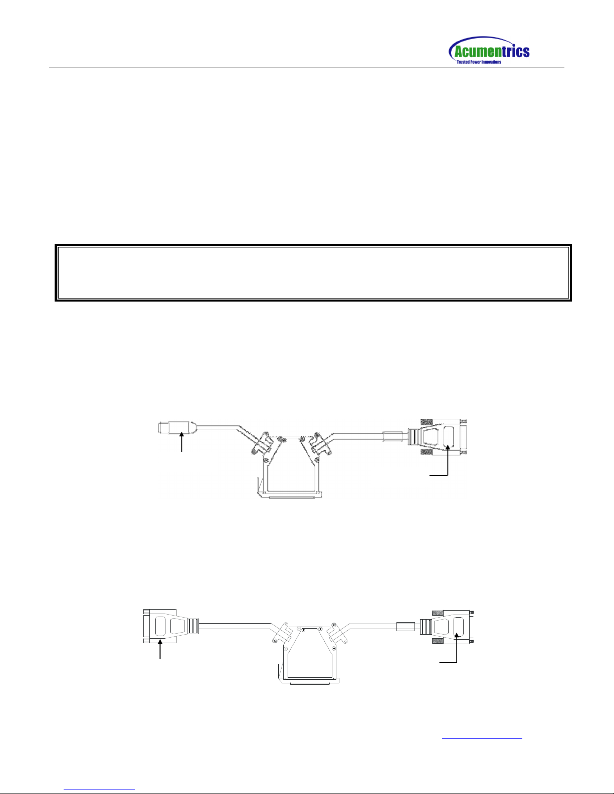
Parallel Operation is ONLY possible using Acumentrics supplied control cables. Refer to documentation supplied
with cables for Parallel Operation.
Remote Operation
(ACG9223 Optional Cable)
CAUTION:
•If AC Outputs are NOT connected properly hazardous voltages may exist in the devices.
•Hazardous voltages may exist in the cables, use caution.
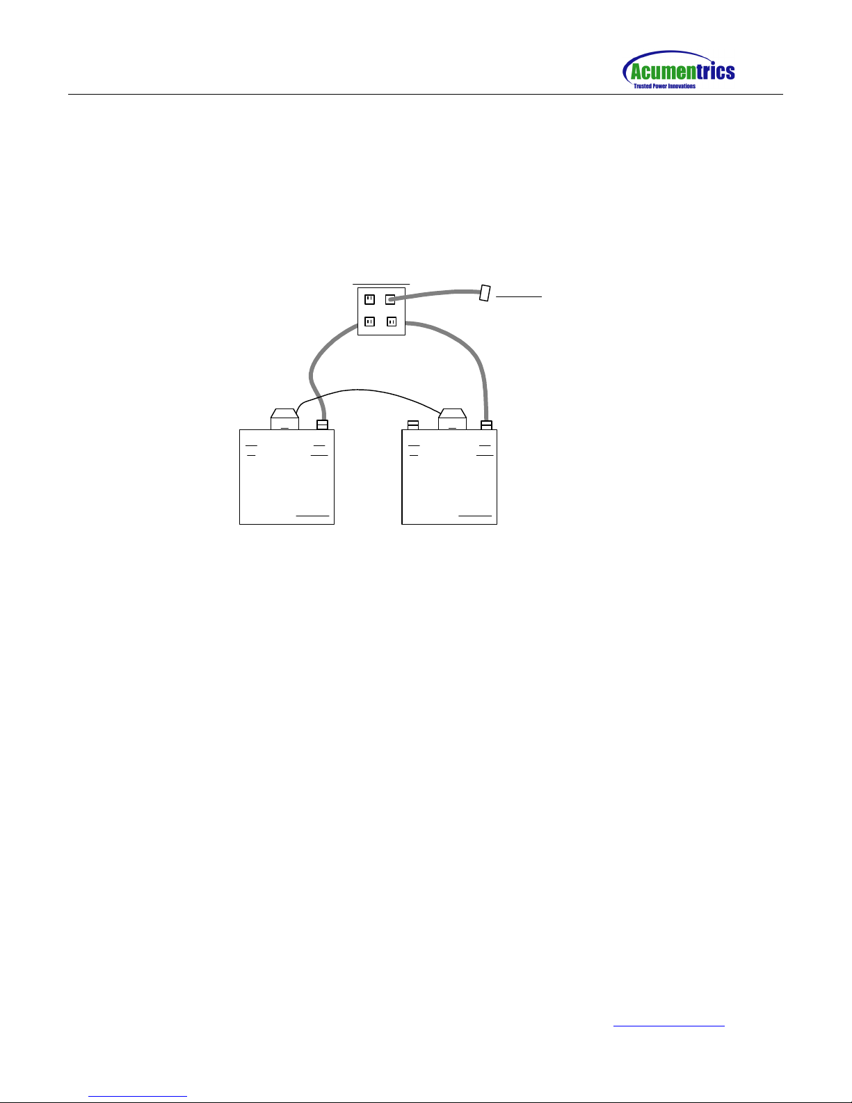
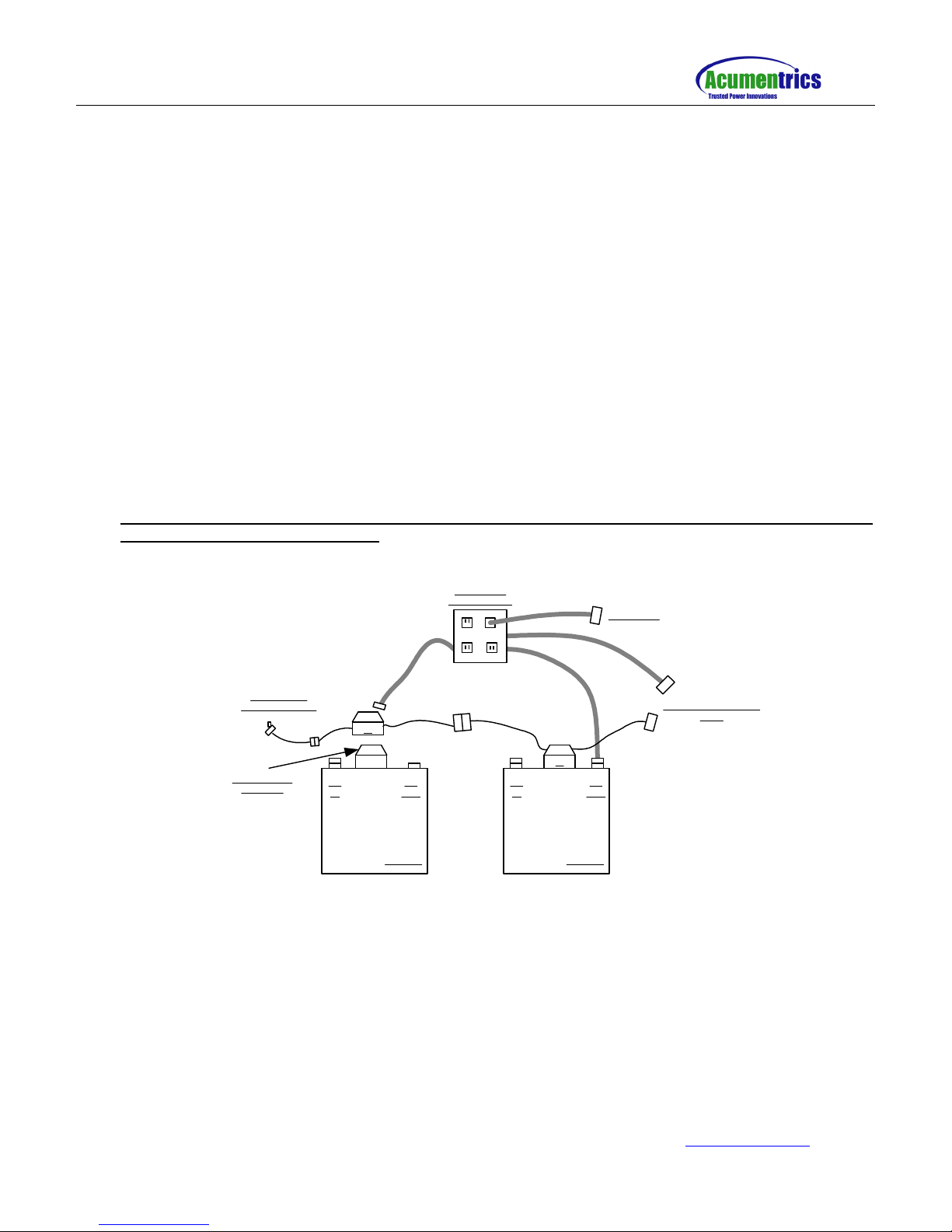
•Attach the 6 Pin Mini-Din to a Double Pole, Double Throw, Momentary Switch.
•Connect the 6 Pin Mini Din (Male) Connector End of the optional ACG9223 cable, for remote on/off control of
the parallel string, to the 6 Pin Mini Din (Female) connector coming out of the PRIMARY Cable.
56
3
4
1
2
MALE
Pin 1
Pin 2
Pin 3
Pin 4
Pin 5
Pin 6
ON
OFF
ON
OFF
NOTE: Specified colors of the wires may be different based on the cable shipped. Ensure the appropriate pin
numbers from the ACG9223 cable are soldered to appropriate switch locations given below.

Parallel Operations Manual for Rugged-UPS 2500 Series
Part Number: 91-0086 Rev. D World Wide Web Site: http:// www.acumentrics.com
20 Southwest Park Westwood, MA. 02090
Phone: (800)-332-0277 Fax: (781)-461-1261
5 of 5
•Hold the switch in the ON position for at least 2 seconds to supply power to ALL units. Hold the switch in the
OFF position for at least 2 seconds to turn ALL units off.
Parallel Units Operated As Standalone
There may be occasions where it is desirable or necessary to operate an Acumentrics ACG2500 Series parallel
unit in a situation where it is not part of a parallel configuration, or needs to be isolated for verification. This is
possible by using an adapter Acumentrics part number ACG9249. However, there are some precautions that
need to be understood
•Ensure all AC circuit breakers are OFF and all outputs are OFF before making or removing any cable
connections.
•Ensure the AC output of the unit to be isolated is not connected in parallel with any other unit.
•Attach the adapter (Part Number ACG9249), to the DB25 Auxiliary Connector Port on the back of any one of
the units.
•The UPS will now be operated from the front panel switch.
•The UPS will be able to supply AC power to a load, not exceeding 2KW.
•This adapter can be connected to any of the UPS units in the setup, following the previous instructions.
•Under NO circumstances should two UPS units ever be operated in parallel unless they are
configured with the parallel cables.
UPS
P
S
AC OUTPUT
JUNCTON BOX
UPS
TO LOAD(S)
TO NEXT SECONDARY
UNIT
TEST CABLE,
WITH ON/OFF SW
AC
OUT
AC
OUT
AC
IN
AC
IN
STANDALONE
ADAPTER
Configuration of a standalone UPS using the adapter
Other manuals for Rugged-UPS 2500 Series
1
Table of contents
Other Acumentrics UPS manuals