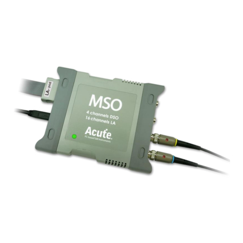
Acute MSO Series User manual

1
皇晶科技股份有限公司 Acute Technology Inc.
Copyright©2018
MSO Series 3 in 1 Analyzer
(Protocol + Logic + Simple DSO) Manual
Publish: 2020/08

2
皇晶科技股份有限公司 Acute Technology Inc.
Copyright©2018
Table of Contents
Chapter 1 Installation and Settings ........................................................................3
Hardware Installation.................................................................................................3
Software installation ..................................................................................................3
Specification Table.....................................................................................................6
Specification Table (International & Microchip) ......................................................8
Chapter 2 Function list and operation..................................................................10
Protocol Analyzer.....................................................................................................10
File..............................................................................................................................10
Operating mode and memory setting..........................................................................13
Show Waveforms........................................................................................................19
Search..........................................................................................................................19
To the end ...................................................................................................................20
Window.......................................................................................................................20
Saved as text file.........................................................................................................21
Detail window.............................................................................................................21
Statistics window........................................................................................................22
Hide Data window......................................................................................................23
Stack Oscilloscope......................................................................................................24
Cursor .........................................................................................................................25
Logic Analyzer.........................................................................................................26
File..............................................................................................................................27
Capture........................................................................................................................31
Advanced Capture Settings.........................................................................................47
Cursor .........................................................................................................................50
Waveform And Report................................................................................................53
Chapter 3 Technical Support.................................................................................57

3
皇晶科技股份有限公司 Acute Technology Inc.
Copyright©2018
Chapter 1 Installation and Settings
Hardware Installation
Connect the USB 3.0 cable to the USB slot on the computer (Pic.1). After confirming that the
connection is complete, you can turn on the software and connect the signal cable to the object to
be tested for observation. Before the measurement, please make sure the GND has been correctly
connected. If it is possible, we suggest twisted pair the Data Pin and GND to improve the signal
quality (Pic.2). If the signal speed is over 150MHz, please use the short cable for
measurement
(Pic.1)
(Pic.2)
Software installation
Please visit the official website of Acute Technology Inc., go to the Download page, and then
select and download the MSO series. After completion of installation, the “start
icon” of MSO series will appear on the desktop and the program set. You can
select either one to start MSO ( ). After starting the software, the main menu screen will
show up. You can choose to enter logic Analyzer or protocol Analyzer.

4
皇晶科技股份有限公司 Acute Technology Inc.
Copyright©2018
Or after entering the function window , you can select the icon below to add Logic Analyzer
or Protocol Analyzer window
Or click the Add Logic Analyzer or Add Protocol Analyzer window within the file functions.
For the first-time use, the following screen will show up. Please set up the working directory that
you will surely use. It is recommended that you choose the hard disk with larger remaining space
for the storage of the working directory.

5
皇晶科技股份有限公司 Acute Technology Inc.
Copyright©2018

6
皇晶科技股份有限公司 Acute Technology Inc.
Copyright©2018
Specification Table
Model
MSO1008E
MSO1116E
MSO2116B
MSO2216B
MSO2216B+
Power
Power Source
USB bus-power (+5V)
Static Power
Consumption
0.9W
Max Power
Consumption
< 3.9W
< 6W
Hardware Interface
USB3.0
Channels (Data / Clock / Ground)
8 / 1 / 23
16 / 1 / 23
Total Memory
2Gb
4Gb
8Gb
Analog Input
Channels
Group I (CH0~7)
Group I, II (CH0~7, CH8~15)
Sample Rate(Group I 或II)
200MHz / 1CH, 100MHz / 2CH, 25MHz / 8CH
Sample Rate(Group I 或II)
The minimum value of Group I or II settings
Bandwidth
40MHz
ADC Bits
12
Digital
Input
Timing Analyzer (Asynchronous)
Available channels (Conventional / Transitional Timing) - Memory per channel
2 GHz
(4 / 3)– 512 Mb
(4 / 3)– 1 Gb
(8 / 7)– 512 Mb
(8 / 7)– 1 Gb
1 GHz
(8 / 6)– 256 Mb
(8 / 6)– 512 Mb
(16 / 14)– 256 Mb
(16 / 14)– 512 Mb
500 MHz
(8 / 6)– 256 Mb
(16 / 12)– 256 Mb
(16 / 16)– 256 Mb
(16 / 16)– 512 Mb
250 MHz and lower
(8 / 6)– 256 Mb
(16 / 16)– 256 Mb
(16 / 16)– 256 Mb
(16 / 16)– 512 Mb
State Clock Rate (Synchronous,
External Clock)
150 MHz
200 MHz
Storage
Conventional Timing, Transitional Timing
Channel to channel skew
< 1ns
Threshold
Group
1 (CH0~7 & CKI)
2 (CH0~7 & CKI, CH8~15)
Range
+20V ~ -20V
Resolution
50mV
Accuracy
±100mV + 5%*Vth
Input Voltage
Non-Destructive
Over +/-42V DC & AC
Operation (Normal/High Division)
-20V ~ +20V / -10V ~ +10V
Sensitivity (0.5/0.75/1 Vpp)
100 MHz / 120 MHz / 150 MHz
180 MHz / 200 MHz / 220 MHz
H/W Schmitt (On/Off)
560 mV / 80 mV
Impedance
1 mΩ / 2 pF
Temperature
Operating / Storage
5°C~45°C (41°F~113°F) / -10°C~65°C (14°F~149°F)
I/O port
Trig-In
TTL 3.3V (Rising / Falling)
Trigger pulse approval
> 8 ns
Trig-Out
TTL 3.3V, Pulse Width
Ref. Clock Input
10MHz, Vpp=3.3 to 5V
Ref. Clock Output
10MHz, TTL 3.3V
Connector type
MCX jack / female
Trigger
Resolution
500ps
Channels
8
16
States
16
Events
16
Pre / Post
Yes
Pass Counter
Yes (0~1048575 times)
Digital
Channel, Pattern, Single / Multi Level, Width, Time-out, External
Analog
Rising / Falling
Bus I
I2C, SPI, UART
Bus II
---
BiSS-C, CAN2.0B/CAN FD, DP_Aux¹, HID over I2C, I2S, LIN2.2, USB PD 3.0

7
皇晶科技股份有限公司 Acute Technology Inc.
Copyright©2018
Bus III
---
DALI, I3C, LPC, MDIO, Mini/Micro LED, MIPI RFFE, MIPI SPMI
2, Modbus, PMBus, Profibus, SMBus, SVI2, USB1.1
Bus IV
---
eMMC 4.5, eSPI, MII, RGMII, RMII, SVID³,
SD 2.0 (SDIO 2.0), Serial Flash (SPI NAND)
Protocol
Analyzer
I
I2C, SPI, UART
II
---
BiSS-C, CAN2.0B/CAN FD, DP_Aux¹, HID over I2C, I2S, LIN2.2, USB PD 3.0
III
---
DALI, I3C, LPC, MDIO, Mini/Micro LED, MIPI RFFE, MIPI SPMI
2, Modbus, PMBus, Profibus, SMBus, SVI2, USB1.1
IV
---
eSPI, MII, RGMII, RMII, SVID³
Software
Features
Power Sequence
---
Input setup .CSV file for Timing Sequence and H/W Strap check.
Measurement
Digital or Analog waveforms
Zoom / Report Window
YES
Note editor
Edit notes on Waveform Window
Quick Bus Decode Setup
YES
Trigger / Auxiliary cursors
1/25
Data Logger
Saved to Hard Disk Drive
Bus Decode
1-Wire, 3-Wire, 7-Segment, A/D Mux Flash, AccMeter, ADC, APML, AVSBus, BiSS-C, BSD, BT1120, CAN
2.0B/FD, Close Caption, CODEC_SSI, DALI, DMX512, DP_Aux¹, EDID, eMMC 5.1/MMC, eSPI, FlexRay,
HD Audio, HDLC, HDQ, HID over I²C, I²C, I²C EEPROM, I²S (PCM, TDM), I3C, IrDA, ITU-R BT.656
(CCIR656), JTAG, JVC IR, LCD1602, LED_Ctrl, LIN 2.2, Line Decoding, Line Encoding, Lissajous, LPC,
LPT, Math, M-Bus, MDDI, MDIO, MHL CBUS, Microwire, Mini/Micro LED, MIPI CSI LP, MIPI DSI LP,
MIPI RFFE, MIPI SPMI 2.0, Modbus, NEC IR, PECI 3.0, PMBus, Profibus, PS/2, PWM, QEI, QI, RC-5, RC-6,
S/PDIF, SD 2.0 (SDIO 2.0), Serial Flash, Serial IRQ, SGPIO, Smart Card, SMBus (SBS, SPD), SMI,
SoundWire, SPI, SPI-NAND, SSI, ST7669, SVI2, SVID², SWD, SWIM, SWP, UART, ULPI, UNI/O, USB 1.1,
USB PD 3.0, Wiegand, ...
Line Decoding
Biphase Mark, Differential-Manchester, Manchester (Thomas, IEEE802.3), Miller, Modified Miller, NRZI, …
Line Encoding
AMI(Standard, B8ZS, HDB3), Biphase Mark, CMI, Differential-Manchester, Manchester (Thomas, IEEE802.4),
MLT-3, Miller, Modified Miller, NRZI, Pseudoternary, …
Dimension
L x W x H (mm3)
123 x 76 x 21(mm3)
Lead Cable
Data / CLK / NC / GND
8 / 1 / 8 / 23
16 / 1 / 0 / 23
Grippers
10
20
Stack Cable
MCX to MCX (30cm)
1
2
¹Optional DP AUX adapter needed.
²Upon request ONLY by users who have signed CNDA with Intel, SVID decode supported by all MSO models
³Upon request ONLY by users who have signed CNDA with Intel, SVID trigger & PA supported by MSO2216B / B+ ONLY.

8
皇晶科技股份有限公司 Acute Technology Inc.
Copyright©2018
Specification Table (International & Microchip)
International
MSO2008W
MSO2116W
MSO2116B
MSO2216B
MSO2216B+
Microchip
MSO2008N
MSO2116N
MSO2116M
MSO2216M
MSO2216M+
Power
Power Source
USB bus-power (+5V)
Static Power
Consumption
0.9W
Max Power
Consumption
< 3.9W
< 6W
Interface
USB3.0
Channel (Data / Clock / Ground)
8 / 1 / 23
16 / 1 / 23
Total Memory
2Gb
4Gb
8Gb
Analog
Input
Channels
Group I (CH0~7)
Group I, II (CH0~7, CH8~15)
Sample Rate (Group I or II)
200MHz / 1CH, 100MHz / 2CH, 25MHz / 8CH
Sample Rate (Group I or II)
The minimum value of Group I or II settings
Bandwidth
40MHz
ADC Bits
12
Digital
Input
Timing Analysis (Asynchronous)
Available channels (Conventional / Transitional Timing) - Memory per channel
2 GHz
(4 / 3)– 512 Mb
(4 / 3)– 1 Gb
(8 / 7)– 512 Mb
(8 / 7)– 1 Gb
1 GHz
(8 / 6)– 256 Mb
(8 / 6)– 512 Mb
(16 / 14)– 256 Mb
(16 / 14)– 512 Mb
500 MHz
(8 / 6)– 256 Mb
(16 / 12)– 256 Mb
(16 / 16)– 256 Mb
(16 / 16)– 512 Mb
250 MHz and lower
(8 / 6)– 256 Mb
(16 / 16)– 256 Mb
(16 / 16)– 256 Mb
(16 / 16)– 512 Mb
State Clock Rate (Synchronous,
External Clock)
150 MHz
200 MHz
Data Storage
Conventional Timing, Transitional Timing
Channel to channel skew
< 1ns
Threshold
Group
1 (CH0~7 & CKI)
2 (CH0~7 & CKI, CH8~15)
Range
+20V ~ -20V
Resolution
50mV
Accuracy
±100mV + 5%*Vth
Input
Voltage
Non-Destructive
Over +/-42V DC & AC
Operation
(Standard / High Resolution)
-20V ~ +20V / -10V ~ +10V
Sensitivity (0.5/0.75/1 Vpp)
100 MHz / 120 MHz / 150 MHz
180 MHz / 200 MHz / 220 MHz
H/W Schmitt (On/Off)
560 mV / 80 mV
Impedance
1 MΩ / 2 pF
Temperature
Operating / Storage
5°C~45°C (41°F~113°F) / -10°C~65°C (14°F~149°F)
I/O port
Trig-In
TTL 3.3V (Rising / Falling)
Trigger pulse approval
> 8 ns
Trig-Out
TTL 3.3V, Pulse Width
Ref. Clock Input
10MHz, Vpp=3.3 to 5V
Ref. Clock Output
10MHz, TTL 3.3V
Connector type
MCX jack / female
Trigger
Resolution
500ps
Channels
8
16
States
16
Events
16
Pre / Post
Yes
Pass Count
Yes (0~1048575 times)
Digital
Channel, Pattern, Single / Multi Level, Width, Time-out, External

9
皇晶科技股份有限公司 Acute Technology Inc.
Copyright©2018
Analog
Rising / Falling
Bus I
I2C
Bus II
---
CAN 2.0B/CAN FD, LIN2.2, SPI, UART (RS232)
Bus III
---
BiSS-C, DALI, DP_Aux¹, HID over I2C, I2S, I3C, LPC, MDIO,
Mini/Micro LED, MIPI RFFE, MIPI SPMI 2, Modbus, PMBus,
Profibus, SMBus, SVI2, USB1.1, USB PD 3.0
Bus IV
---
eMMC 4.5, eSPI, MII, RGMII, RMII, SVID³,
SD 2.0 (SDIO 2.0), Serial Flash (SPI NAND)
Protocol
Analyzer
I
I2C
II
---
CAN 2.0B/CAN FD, LIN2.2, SPI, UART (RS232)
III
---
BiSS-C, DALI, DP_Aux¹, HID over I2C, I2S, I3C, MDIO, MIPI
RFFE, Modbus, PMBus, Profibus, PWM, SMBus, USB1.1,
USB PD 3.0
IV
---
eSPI, MII, RGMII, RMII, SVID³
Software
Features
Power Sequence
---
Input setup .CSV file for Timing Sequence and H/W Strap check.
Measurement
Digital or Analog waveforms
Zoom / Report Window
YES
Note editor
Edit notes on Waveform Window
Quick Bus Decode Setup
YES
Trigger / Auxiliary cursors
1/25
Data Logger
Saved to Hard Disk Drive
Bus Decode
1-Wire, 3-Wire, 7-Segment, A/D Mux Flash, AccMeter, ADC, APML, AVSBus, BiSS-C, BSD, BT1120, CAN
2.0B/FD, Close Caption, CODEC_SSI, DALI, DMX512, DP_Aux¹, EDID, eMMC 5.1/MMC, eSPI, FlexRay, HD
Audio, HDLC, HDQ, HID over I²C, I²C, I²C EEPROM, I²S (PCM, TDM), I3C, IrDA, ITU-R BT.656 (CCIR656),
JTAG, JVC IR, LCD1602, LED_Ctrl, LIN 2.2, Line Decoding, Line Encoding, Lissajous, LPC, LPT, Math, M-Bus,
MDDI, MDIO, MHL CBUS, Microwire, Mini/Micro LED, MIPI CSI LP, MIPI DSI LP, MIPI RFFE, MIPI SPMI 2.0,
Modbus, NEC IR, PECI 3.0, PMBus, Profibus, PS/2, PWM, QEI, QI, RC-5, RC-6, S/PDIF, SD 2.0 (SDIO 2.0), Serial
Flash, Serial IRQ, SGPIO, Smart Card, SMBus (SBS, SPD), SMI, SoundWire, SPI, SPI-NAND, SSI, ST7669, SVI2,
SVID², SWD, SWIM, SWP, UART, ULPI, UNI/O, USB 1.1, USB PD 3.0, Wiegand, ...
Line Decoding
Biphase Mark, Differential-Manchester, Manchester (Thomas, IEEE802.3), Miller, Modified Miller, NRZI, …
Line Encoding
AMI(Standard, B8ZS, HDB3), Biphase Mark, CMI, Differential-Manchester, Manchester (Thomas, IEEE802.4),
MLT-3, Miller, Modified Miller, NRZI, Pseudoternary, …
Dimension
L x W x H (mm3)
123 x 76 x 21
Lead Cable
Data / CLK / NC / GND
8 / 1 / 8 / 23
16 / 1 / 0 / 23
Grippers
10
20
Stack Cable
MCX to MCX (30cm)
1
2
¹Optional DP AUX adapter needed.
²Upon request ONLY by users who have signed CNDA with Intel, SVID decode supported by all MSO models
³Upon request ONLY by users who have signed CNDA with Intel, SVID trigger & PA supported by MSO2216B / B+ ONLY.

10
皇晶科技股份有限公司 Acute Technology Inc.
Copyright©2018
Chapter 2 Function list and operation
Protocol Analyzer
File
Open fill: Load the file
Save file: Save the current window to file
Save as: Save with a new file name with specified storage range
Save all: Save all Protocol Analyzer/Logic Analyzer windows to files
Add Protocol Analyzer: Add a Protocol Analyzer window
Add Logic Analyzer: Add a Logic Analyzer window
Convert to Logic Analyzer: When the “show waveform” capture mode is enabled;
you can click this function to transfer the waveform and setting parameters into the Logic
Analyzer window and continue to use the Logic Analyzer window to capture Protocol.
Stack Oscilloscope: You may stack a DSO to become a MSO under the Protocol
Analyzer mode. But you must choose the “show waveform” capture mode to capture the protocol
data with the waveforms. Then, click the DSO icon to enter the Logic Analyzer window.
Language: Display language. You can select English, Traditional Chinese, or Simplified
Chinese
System environment settings: Here you can set the working directory, the label height,
whether to load the last setting, the waveform display mode and its color

11
皇晶科技股份有限公司 Acute Technology Inc.
Copyright©2018
Capture
Protocol Settings
Style 1 for those protocols with easy setting
1. Select the Protocol
2. Channel setting
3. Waveform Preview: The signal’s waveform and frequency are automatically detected.
4. Options: 可You can set the capture and decoding parameters for Protocol
5. Threshold: It can be set according to the voltage level of the signal.

12
皇晶科技股份有限公司 Acute Technology Inc.
Copyright©2018
Style 2 for those protocols needs more setting
1. Select the Protocol
2. Set the Sample Rate
3. Channel setting
4. Trigger on
5. Options: You can set the capture and decoding parameters for Protocol.
6. Threshold: It can be set according to the voltage level of the signal.

13
皇晶科技股份有限公司 Acute Technology Inc.
Copyright©2018
Operating mode and memory setting
There are three modes for operating mode and memory setting ( )
Mode 1 Protocol Analyzer
Functional description
Captured data will be sent back to the PC for real time display. You can immediately
see the protocol data right away.
Rule:
1. Data can be seen immediately.
2. If the amount of captured data is not big, you do not have to set the amount
of memory.
Notice for use:
As data will be captured and displayed at the same time the performance
requirement for the USB and the computer will be higher. If the computer
cannot handle the data in time, the device may automatically stop due to full
memory.
If software is in operation during the capture period the computer will
respond more slowly.

14
皇晶科技股份有限公司 Acute Technology Inc.
Copyright©2018
Rules for repetitive times and automatic stop
Repetitive Times
If it is not enabled, the device will be stop ped after the stop condition matched.
If it is enabled, the device will be stop ped after the stop condition matched, then
save the captured data and repeat the captures again, according to the number of
captures that has been set.
If the number of captures is set at 0, the device will capture data repetitively.
Three Stop Conditions to stop the device automatically are provided as follows:
Maximum PC RAM Limit
Stop the capture when the stored data size matched the size of allocated PC
RAM, this limitation will avoid excessive use of the PC RAM, which may
resulting in insufficient memory and unstable performance of the operating
system.
Number of Data Lines
Stop the capture when the stored data line number matched the setup data line
number, you can select this function if you need only sufficiently number of
data lines without capturing data for a long time. This function is set to OFF by
default.
Maximum Device Memory Limit
Stop the capture when the device memory is filled to the set condition.

15
皇晶科技股份有限公司 Acute Technology Inc.
Copyright©2018
Mode 2 Protocol Logger
Functional description:
Data will be sent back to the PC for saving without being processed and displayed. Only
after the user presses to stop the operation will data begin to be processed and displayed.
Rule:
1. As long as the hard disk is big enough to respond quickly enough, it can
save a great amount of data.
2. Logger file (.LOG) can be opened for Analyzer later, no need to analyze
them right after their capture
Notice for use:
1. Performance requirements for the USB and the computer (hard disk) are
high.
2. Due to the large amount of logger data, the requirements for the hard disk
space and the time for follow up Analyzer will be very great.
Run data process after capture stopped
Check this option to process the data after Logger capture stopped, or the software

16
皇晶科技股份有限公司 Acute Technology Inc.
Copyright©2018
will only save the logger data without analyzing process.
You can reload the .LOG file from Load file to reanalyze the data.
Whether you check the results immediately or load them into the file, the file name
will be converted from LOG to BFW.

17
皇晶科技股份有限公司 Acute Technology Inc.
Copyright©2018
Mode 3 Protocol Monitor
Functional description
Data will be kept in the device and overwrote the old data without returning to the PC,
the capture can be stopped by user manually or by trigger condition matched, then the
device will fill the device memory until memory full and return to PC for display.
Rule:
1. During the capture period, data are not returned to the PC, reducing the
performance requirements on the USB and the computer.
2. The total amount of data is the total amount of device memory.
3. Trigger conditions can be set and monitored for a long time Device
memory will be filled only when the amount of data matches the trigger
conditions.
Notice for use:
1. If the trigger is not set or you have set the trigger but want to retrieve the
data before the memory is full, you must manually press “Stop” to send data
back to the computer.

18
皇晶科技股份有限公司 Acute Technology Inc.
Copyright©2018
Work options
Maximum Device memory limit
If the checkbox is unchecked, the max memory of the device is used.
If the checkbox is checked, the usage ratio of the device memory can be adjusted;
less memory can shorten the subsequent processing time.
Data capture will continue until ”Stop“ is pressed (Wait for stop)
Data capture will continue. If memory is full the new data will be still captured to
replace the old data, until “Stop” is pressed Then the newest data will be sent back
to the computer.
Data capture will continue until the trigger condition is met (Wait for Trigger)
If the trigger condition is not set, there will be no Pre/Post Trigger relationship and
only the Capturing will be shown until the device memory is full. If the trigger
condition is set, data will be filled according to the set Trigger Position. Data
capture will continue until the trigger condition is met or “Stop” is pressed Then,
data capture will stop and the set memory will be filled.

19
皇晶科技股份有限公司 Acute Technology Inc.
Copyright©2018
Show Waveforms
If “Show Waveforms” is selected, the device will capture the waveform data, but show the
waveforms only after the capture stops Selection of Show Waveforms will take up more
device memory .
When “Show Waveforms” is enabled, the waveform area will provide the following
functions:
1. Bus Decode
Press this button to refresh the bus decode.
2. Stop the bus decode
This button can stop the bus decode right away.
3. Add User Notes
4. Waveform zoom in/out
This button can scale up or down the waveforms, but it is recommended to use the mouse
cursor to zoom the waveforms in or out for your convenience.
Search
Search function can search data in the report window.
1. Enter the search text
A mark will appear in front of ther data meeting the search criteria.
2. Search the previous piece / the next piece of data.
3. Specifiy all fields o r target fields for search.
Specifiy fields for search can reduce the search range, thus speeding up the search.

20
皇晶科技股份有限公司 Acute Technology Inc.
Copyright©2018
In actual search, the searched data will be shown in green background color togther with the
total number of packets found. If no data is found, the search result
will be shown in orange background color.
To the end
When viewing data, you press this button to move directly to the last end of data If you press
this button while the device is capturing data, the most up to date data will be displayed.
Window
Select to enable/disable multiple display lists, such as: Search List, Statistic List …etc.
1. Select to display different display list.
2. Use the control buttons to move the current position, or input row number to jump to
specified row.
3. Use the control buttons to add /remove selected row to Bookmark List.
This manual suits for next models
10
Table of contents
Other Acute Measuring Instrument manuals