Yamaha 6Y8-2819V-00 User manual

COMMAND LINK
MULTIFUNCTION METER
(ROUND)
OPERATION MANUAL
6Y8-2819V-00

To the owner
Thank you for choosing the Yamaha Com-
mand Link Multifunction Meter.
This Operation Manual contains information
you will need for proper operation.
A thorough understanding of these simple
instructions and of those in the Owner’s
Manual of the outboard motor will help you
obtain maximum enjoyment of your new
Yamaha. This manual should be considered
a permanent part of this meter and should
remain with it even if the meter is subse-
quently sold.
In this Operation Manual particularly impor-
tant information is distinguished in the fol-
lowing ways.
The Safety Alert Symbol means
ATTENTION! BECOME ALERT! YOUR
SAFETY IS INVOLVED!
WARNING
Failure to follow WARNING instructions
could result in severe injury or death to
the machine operator, a bystander, or a
person inspecting or repairing the out-
board motor.
CAUTION:
A CAUTION indicates special precau-
tions that must be taken to avoid damage
to the outboard motor.
NOTE:
A NOTE provides key information to make
procedures easier or clearer.
COMMAND LINK
MULTIFUNCTION METER
(ROUND)
OPERATION MANUAL
©2005 by Yamaha Motor Co., Ltd.
1st Edition, March 2005
All rights reserved.
Any reprinting or unauthorized use
without the written permission of
Yamaha Motor Co., Ltd.
is expressly prohibited.
Printed in Japan

The Command Link Multifunction Meter
enables the display of information through
digital communication with the engine.
Optional parts such as the speed sensor,
cooling water pressure sensor, Triducer-
Multi sensor, and GPS are described in this
manual by assuming that the parts are
installed and set up on the outboard motor.
The Command Link Multifunction Meter
described in this manual consists of the fol-
lowing.
•Tachometer unit
(Part No.: 6Y8-8350T-1*)
•Speed & Fuel meter unit
(Part No.: 6Y8-83500-1*)
The Command Link Multifunction Meter is
compatible with the following outboard
motors.
4-stroke models:
Fuel injection models only
2-stroke models:
HPDI models only
The operations of the set button and the
mode button are described in this manual as
follows.
Button operations:
•
Press the set button one time.
•
Press the mode button one time.
•or
Press the set button or the mode button
one time.
•(1 second)
Press the set button for 1 second.
•(4 seconds)
Press the mode button for 4 seconds.
•(10 seconds)
Press the set button for 10 seconds.
•(1 second) (2 times)
Press the mode button two times, 1 sec-
ond each time.
•+
Press the set button and the mode button
simultaneously.
•+ (1 second)
Press the set button and the mode button
simultaneously for 1 second.


Table of contents
Tachometer unit
Speed & Fuel meter
unit
Setting up the
meters
1. Tachometer unit ....................... 1
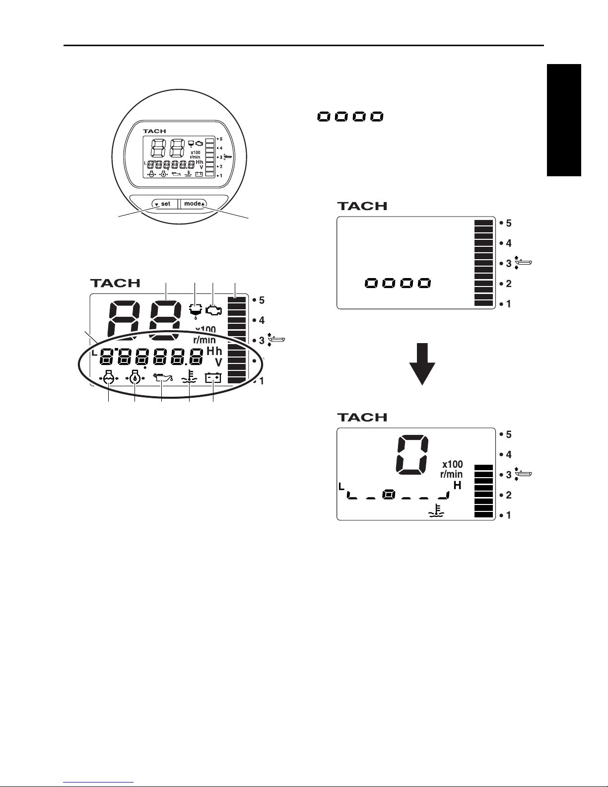
Description .................................. 2
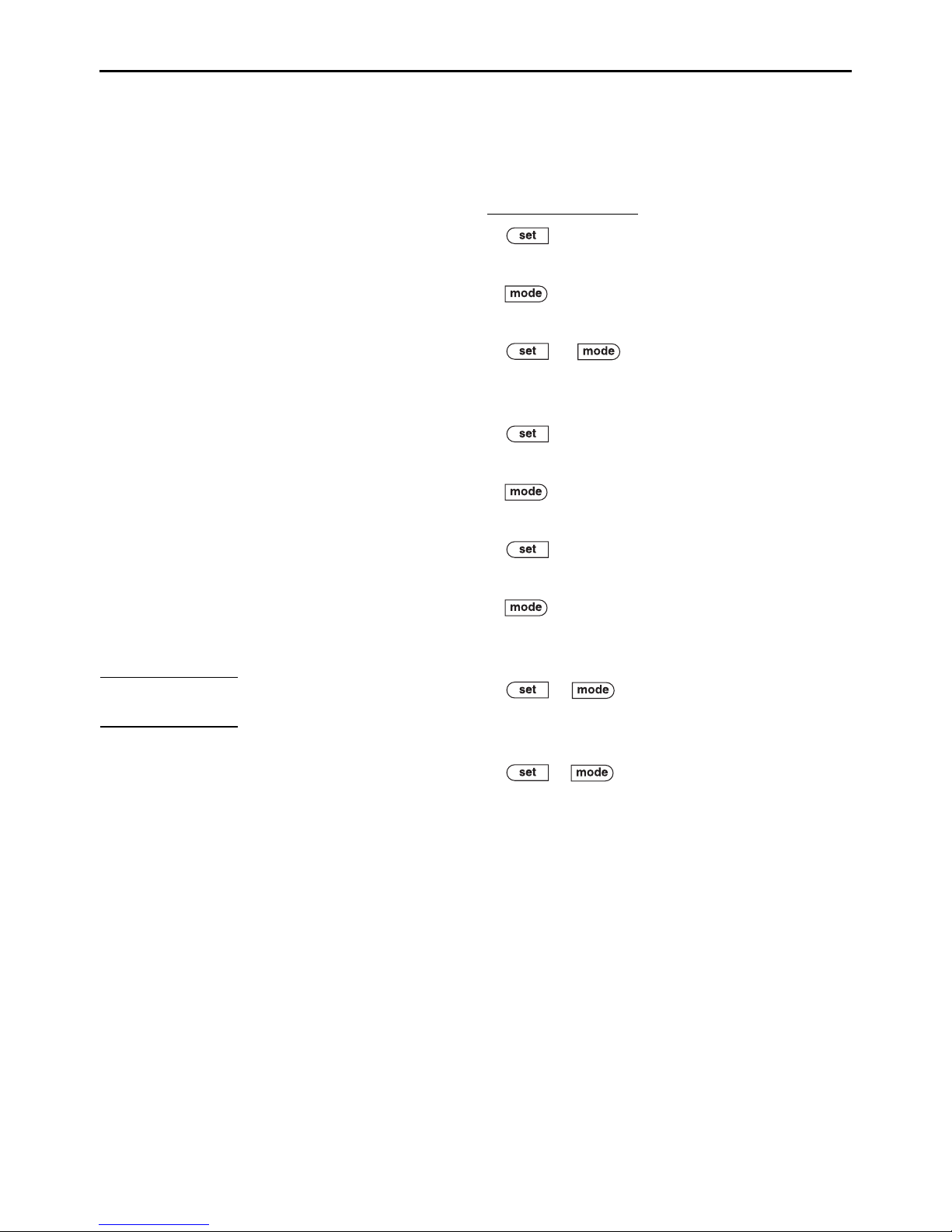
Activating the meter .................... 2
Periodic maintenance
notification............................. 3
Tachometer ................................. 3
Trim meter................................... 3
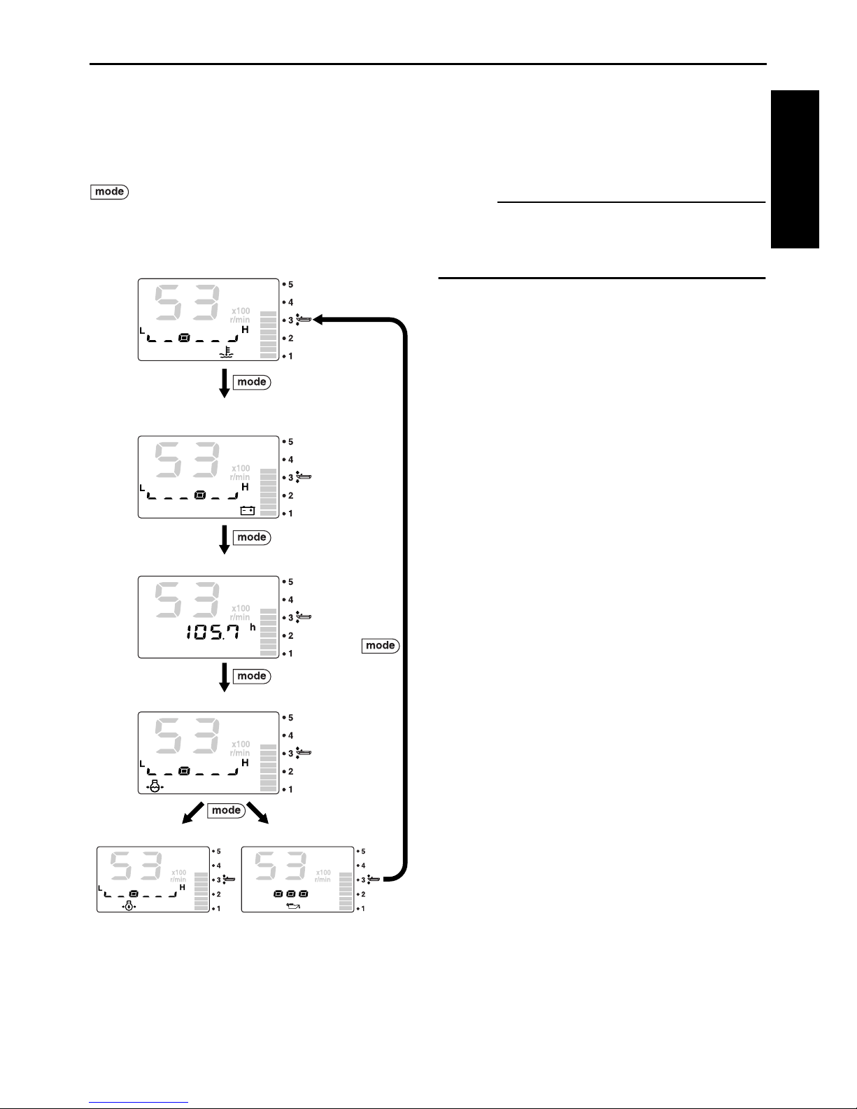
Multifunction display.................... 4
Cooling water/engine
temperature display............... 5
Battery voltage display ............. 6
Total hour/Trip hour display ..... 7
Cooling water pressure display
(optional: cooling water
pressure sensor has been
installed)................................ 7
Oil pressure display
(4-stroke models) .................. 8
Oil level display
(2-stroke models) .................. 9
Water detection warning .......... 9
Changing backlight settings ...... 10
Adjusting trolling speed ............. 10
Changing settings
(custom mode) ....................... 11
Switching to custom mode ..... 11
01 (resetting maintenance
intervals).............................. 12
02 (setting trim angle) ............ 12
03 (setting corresponding
engine) ................................ 13
Service functions....................... 14
Diagnosis ............................... 14
Resetting engine number ....... 15
2. Speed & Fuel meter unit ........ 16
Description ................................ 17
Activating the meter .................. 17
Speedometer............................. 18
Fuel meter ................................. 19
Multifunction display.................. 19
Fuel flow display .................... 20
Fuel economy display ............ 21
Total fuel consumption
display................................. 21
Ambient water temperature
display (optional:
Triducer-multi sensor has
been installed) .................... 22
Depth display (optional:
Triducer-multi sensor has
been installed) .................... 22
Clock (optional: GPS has
been installed) .................... 23
Trip display (optional: speed
sensor has been
installed) ............................. 23
Changing backlight settings...... 23
Changing settings
(custom mode)....................... 24
Switching to custom mode ..... 24
01 (setting displayed units) .... 24
02 (setting fuel sensor) .......... 26
03 (setting correction value) .. 26
3. Setting up the meters ............ 28
Activating for the first time......... 28
Setting the initial settings .......... 28
Tachometer unit..................... 28
Speed & Fuel meter unit: ....... 28

1
1. Tachometer unit
NOTE:
Depending on the model of the outboard motor, some functions may not be compatible. For
information on models which contain the compatible functions, consult a Yamaha dealer.
Tachometer
The tachometer
shows the engine
revolutions per
minute. (Page 3)
Trim meter
The trim meter shows
the trim angle of the
outboard motor in 13
levels. (Page 3)
Multifunction display (Page 4)
· You can switch each engine information and show it using numeric values
or graphics. In addition, when an engine malfunction occurs, each indicator
blinks to warn of the malfunction.
Cooling water/engine temperature display (Page 5)
Battery voltage display (Page 6)
Total hour/Trip hour display (Page 7)
Cooling water pressure display (optional) (Page 7)
Oil pressure display (4-stroke models) (Page 8)
Oil level display (2-stroke models) (Page 9)
Water detection warning (Page 9)
· Periodic maintenance intervals are notified.
Periodic maintenance notification (Page 3)
Adjusting trolling speed
or : To adjust the trolling speed
randomly. (Page 10)

2
Tachometer unit
Description
1set button
2mode button
1Tachometer
2Trim meter
3Multifunction display
4Water detection warning indicator
5Maintenance indicator
6Cooling water pressure
7Oil pressure (4-stroke models)
8Oil level (2-stroke models)
9Cooling water/engine temperature
0Battery voltage
Activating the meter
When the engine start switch is turned to
ON, the meter is activated and
“”appears on the multifunction
meter. Then, all the displays come on and
the display switches to the normal display
after the total hour display comes on.
2
1
12
3
45
678 90
Description/Activating the meter

3
Periodic maintenance notification
When the hours of engine operation exceed
100 hours, the elapsed time from the previ-
ous maintenance period (when the meter
was reset) blinks.
or : To return to the normal dis-
play.
NOTE:
•The elapsed time blinks every time the
engine is started until it is reset. In addi-
tion, the maintenance indicator ( )
remains on until it is reset.
•When the hours of engine operation
exceed 100 hours and the periodic main-
tenance notification is activated, consult
an authorized Yamaha dealer for periodi-
cal maintenance.
•To reset the maintenance period, see “01
(resetting maintenance intervals)”in
“Changing settings (custom mode).”
Tachometer
The tachometer shows the engine revolu-
tions per minute.
Trim meter
The trim meter shows the trim angle of the
outboard motor in 13 levels.
When the angle of the outboard motor
exceeds the trim range, the top segment
blinks.
Blinks
Blinks
Tachometer/Trim meter

4
Tachometer unit
Multifunction display
The multifunction display shows various
information using numeric values or graph-
ics.
: Press to switch between the displays.
When the engine start switch is turned to
OFF, the last display shown is shown first
when the engine start switch is turned to ON
again.
NOTE:
If an optional sensor is not connected to the
meter, the corresponding display will not be
displayed.
Cooling water pressure
Oil pressure (4-stroke)
Oil level (2-stroke)
Battery voltage level/
Battery voltage value
Cooling water/
engine temperature
Total hour/Trip hour
Multifunction display

5
Cooling water/engine temperature
display
The cooling water/engine temperature indi-
cator ( ) comes on and the cooling
water temperature or the engine tempera-
ture is shown in 6 levels.
When the engine overheats, the cooling
water/engine temperature indicator ( )
blinks to warn of the malfunction.
CAUTION:
• When the overheat warning comes on,
turn the engine off and check the cool-
ing water inlet for clogs.
• If you cannot locate and correct the
cause, consult a Yamaha dealer.
NOTE:
The cooling water/engine temperature dis-
play shows “L”for low and “H”for high.
Blinks
Cooling water/engine temperature display

6
Tachometer unit
Battery voltage display
The battery voltage indicator ( ) comes
on and the battery voltage of the engine is
shown in 6 levels or the voltage value is
shown.
: Press to switch between the display
formats.
When the battery voltage decreases to 12
volts or less or increases to 16 volts or more
the voltage value blinks.
When the battery voltage decreases below
the voltage that is required by the engine,
the battery voltage indicator ( ) blinks
to warn of the malfunction.
CAUTION:
•When the low battery voltage warning
comes on, check the battery and the
wiring.
•If you cannot locate and correct the
cause, consult a Yamaha dealer.
NOTE:
The battery voltage level display shows “L”
for low and “H”for high.
Battery voltage level
Battery voltage value
Blinks
Blink
Battery voltage display

7
Total hour/Trip hour display
The total hour display shows the total hours
of engine operation and the trip hour display
shows the trip hours (T).
: Press to switch between the display
formats.
+ (1 second): To reset the trip
hours (T).
NOTE:
The total hours of engine operation cannot
be reset.
Cooling water pressure display
(optional: cooling water pressure sensor
has been installed)
The cooling water pressure indicator ( )
comes on and the cooling water pressure is
shown in 6 levels.
CAUTION:
•When the cooling water pressure
decreases to 10 psi or less, turn the
engine off and check the cooling water
inlet for clogs.
•If you cannot locate and correct the
cause, consult a Yamaha dealer.
NOTE:
The cooling water pressure level display
shows “L”for low and “H”for high.
Total hour
Trip hour (T)
Blinks
Blinks
Blinks 10 psi
Total hour/Trip hour display/Cooling water pressure display

8
Tachometer unit
Oil pressure display (4-stroke models)
The oil pressure indicator ( ) comes on
and the engine oil pressure is shown in 6
levels.
When the engine oil pressure drops too low,
the oil pressure indicator ( ) blinks to
warn of the malfunction.
CAUTION:
•Do not operate the engine without
engine oil. Severe engine damage can
result.
•Check the oil level by following the
procedure described in the engine
Owner’s Manual.
•If you cannot locate and correct the
cause, consult a Yamaha dealer.
NOTE:
•The oil pressure display shows “L”for low
and “H”for high.
•The low oil pressure warning does not dis-
play the engine oil level.
•Depending on the model of the outboard
motor, the oil pressure display may not be
available.
•Depending on the operating conditions
such as when the engine is operated at
extremely low speeds, the oil pressure
may be shown as low even when the
engine is operating properly.
Blinks
Oil pressure display (4-stroke models)

9
Oil level display (2-stroke models)
The oil level indicator ( ) comes on and
the engine oil level is shown in 3 levels.
When the engine oil level is low, the oil level
indicator ( ) blink to warn of the mal-
function.
CAUTION:
Do not operate the engine without engine
oil. Severe engine damage can result.
Water detection warning
When water has accumulated in the water
separator (fuel filter), the water detection
warning indicator ( ) blinks to warn of
the malfunction. This function is not avail-
able for outboard motors that are not
equipped with the water detection warning
function.
CAUTION:
When the water detection warning comes
on, turn the engine off and remove the
water from the water separator (fuel fil-
ter) by following the procedure described
in the Owner’s Manual of the outboard
motor. A malfunction can result if fuel
mixed with water is sent to the engine.
NOTE:
or : To deactivate the buzzer.
Blink
Blinks
Oil level display (2-stroke models)/Water detection warning

10
Tachometer unit
Changing backlight settings
You can turn the backlight on or off, or
change the brightness level of the backlight
for all meters synchronized.
1. + : To activate the backlight
mode.
2. : Press to switch between the five
brightness levels (1–5).
: To switch between the backlight
on and “OFF.”
3. + : To return to the normal
display.
NOTE:
•The backlight default settings are “OFF”
and brightness level 1.
•If no operations are carried out for 5 sec-
onds or more, the display returns to the
normal display.
•The backlight settings can be changed
from all meters and all displays.
Adjusting trolling speed
You can adjust the trolling speed randomly
by increasing or decreasing it approximately
50 r/min.
When in the trolling speed setting mode, the
display switches to the normal display when
the engine speed is increased (within 3,000
r/min) using the throttle. When the throttle is
closed, the display returns to the trolling
speed setting mode.
This function is not available for outboard
motors that are not equipped with the trolling
speed adjustment function.
1. (1 second): To activate the trolling
speed setting mode.
2. : To decrease the engine speed.
3. : To increase the engine speed.
4. : To return to the normal display
and to the default engine idle speed.
Changing backlight settings/Adjusting trolling speed

11
NOTE:
•Trolling is affected by currents and other
operating conditions and may differ from
the actual engine speed.
•The default engine idle speed is reset
automatically when the display is switched
to the normal display. The default engine
idle speed is also reset automatically
when the engine is turned off or when the
engine speed exceeds 3,000 r/min.
•When warming up a cold engine, the troll-
ing speed cannot be decreased below the
specified engine idle speed.
•Depending on the model of the outboard
motor, some functions may not be com-
patible. For information on models which
contain the compatible functions, consult
a Yamaha dealer.
Changing settings (custom mode)
Switching to custom mode
In the custom mode, you can change the
meter function settings. Each setting func-
tion number is shown in the tachometer dis-
play.
1. Turn the engine off and the engine start
switch to ON.
2. (4 seconds): To activate the cus-
tom mode.
3. (1 second): Press to switch
between the setting function numbers
and to switch to the change settings dis-
play.
4. Change each setting and return to the
normal display. To change the settings,
see the corresponding sections for each
setting function.
NOTE:
If no operations are carried out for 30 sec-
onds or more or if the engine is started, the
settings will not be applied and the display
returns to the normal display.
01 (resetting maintenance intervals)
03 (setting corresponding engine)
02 (setting trim angle)
(1sec.)
(1sec.)
(1sec.)
Changing settings (custom mode)

12
Tachometer unit
01 (resetting maintenance intervals)
You can reset the elapsed time from the
previous maintenance interval (when the
meter was reset).
1. Turn the engine off and the engine start
switch to ON.
2. (4 seconds): To activate the cus-
tom mode and to switch to the resetting
display.
3. + (1 second): To reset the
elapsed time to “0h”and return to the
normal display.
NOTE:
Press the button for 1 second from
step 2 to cancel the resetting of the elapsed
time and return to the normal display.
02 (setting trim angle)
You can set the trim angle to zero.
Fully trim the outboard motor down.
1. Turn the engine off and the engine start
switch to ON.
2. (4 seconds): To activate the cus-
tom mode.
3. (1 second): To switch between
the setting function numbers and to
switch to the zero adjustment display.
4. + (1 second): To adjust the
trim angle to zero using the current trim
position as the standard value and
return to the normal display.
NOTE:
•When one segment is displayed, the trim
angle of the outboard motor is adjusted to
zero (full trim in).
•Press the button for 1 second from
step 3 to cancel the adjustment of the trim
angle to zero and return to the normal dis-
play.
Blinks
01 (resetting maintenance intervals)/02 (setting trim angle)

13
03 (setting corresponding engine)
You can select the engines that are compat-
ible to this meter. The port outboard motor is
set to “-1- (engine number 1)”and the star-
board outboard motor is set to “-2- (engine
number 2).”
1. Turn the engine off and the engine start
switch to ON.
2. (4 seconds): To activate the cus-
tom mode.
3. (1 second) (2 times): Press to
switch between the setting function
numbers and to switch to the change
settings display.
4. : To switch between the displayed
engine numbers.
5. (1 second): To change the corre-
sponding engine and return to the nor-
mal display.
NOTE:
•The meters are set at the factory to
“-1- (engine number 1).”
•To reset an engine number, see “Reset-
ting engine number”in “Service func-
tions.”
-1- (engine number 1)
-4- (engine number 4)
-3- (engine number 3)
-2- (engine number 2)
03 (setting corresponding engine)

14
Tachometer unit
Service functions
Diagnosis
You can display the self-diagnosis results of
the engine.
(10 seconds): To display the diagno-
sis codes.
When there are no malfunctions, the “-01-”
diagnosis code is displayed.
When a malfunction occurs, the correspond-
ing diagnosis codes, except “-01-,”are dis-
played.
When there are multiple diagnosis codes,
press the button to display the next
code number.
(1 second): To return to the normal
display.
CAUTION:
When a diagnosis code other than “-01-”
is displayed, the engine cannot be oper-
ated normally. Consult a Yamaha dealer.
NOTE:
Although the custom mode is activated after
a few seconds while the button is
being pressed, continue to press the button
for 10 consecutive seconds to activate the
diagnosis mode.
Service functions

15
Resetting engine number
When replacing the engines of multiple out-
board motors or resetting the setting order,
reset all engine numbers to “-1- (engine
number 1).”
1. Turn the engine off and the engine start
switch to ON.
2. (10 seconds): “-00-” will be dis-
played for 1 second.
3. Turn the engine start switch to OFF.
The engine number is reset after
approximately 10 seconds.
4. Turn the engine start switches to ON in
order from port to starboard.
NOTE:
• The engine numbers are stored in the
ECM (Engine Control Module) of each
engine for engine identification.
• The engine numbers are stored in the
ECM (Engine Control Module) when the
engine start switch is first turned to ON
after being connected. The numbers are
stored in order from number one to num-
ber four starting from the port outboard
motor. When multiple outboard motors are
installed, be sure to wait at least 2 sec-
onds before turning each engine start
switch to ON.
Service functions
Table of contents
Other Yamaha Measuring Instrument manuals

Yamaha
Yamaha 6Y8- 2819U-00 User manual

Yamaha
Yamaha YPDR601 User manual

Yamaha
Yamaha YM-2000 User manual

Yamaha
Yamaha HR-VP48U User manual

Yamaha
Yamaha MB02R96 User manual

Yamaha
Yamaha MB02R96 User manual

Yamaha
Yamaha Tenor User manual

Yamaha
Yamaha MB1000 User manual

Yamaha
Yamaha MT44D User manual

Yamaha
Yamaha MZ-N10 User manual
Popular Measuring Instrument manuals by other brands

Bimmer Retrofit
Bimmer Retrofit GAT Handheld Coder Pro+ user manual

PCB Piezotronics
PCB Piezotronics HT352A21/NC Installation and operating manual

Bosch
Bosch IVS-SLIM installation manual

ZMD
ZMD TSic LABkit User manual and technical description

HT Italia
HT Italia HT77C user manual

DynAmp
DynAmp LKAT2 Installation, operation and service instructions