ACutter A200E User manual

A200E Electric Fiber Laser
Cutting Head
Version V1.0
WUHAN AU3TECH TRADING CO., LTD
www.au3tech.com
:027-82726630
Fax: :027-82726630
Daijiashan Technology Park,
No.888 Hanhuang Road.

CONTENT
ABSTRACT ................................................................................................................................................... 2
KEY POINTS ................................................................................................................................................................................. 2
READER OBJECTS ....................................................................................................................................................................... 2
MODIFICATION RECORDS ........................................................................................................................................................ 2
INTRODUCTION ....................................................................................................................................... 3
PRODUCT HIGHLIGHTS ............................................................................................................................................................. 3
STRUCTURE .................................................................................................................................................................................. 3
PRODUCT CONFIGURATION ................................................................................................................. 5
TECHNICAL PARAMETERS ......................................................................................................................................................... 5
CONFIGURATION LIST ............................................................................................................................................................... 5
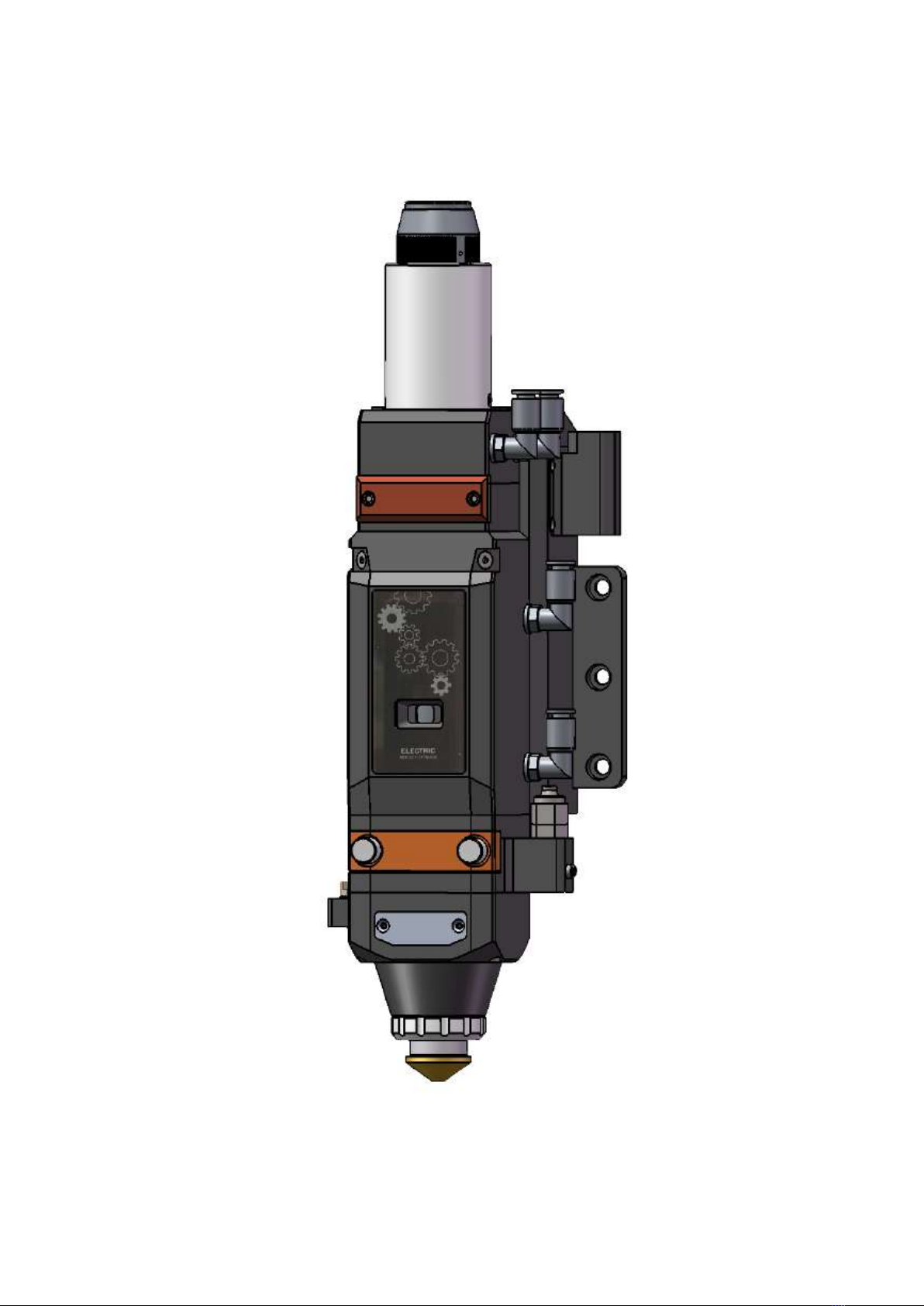
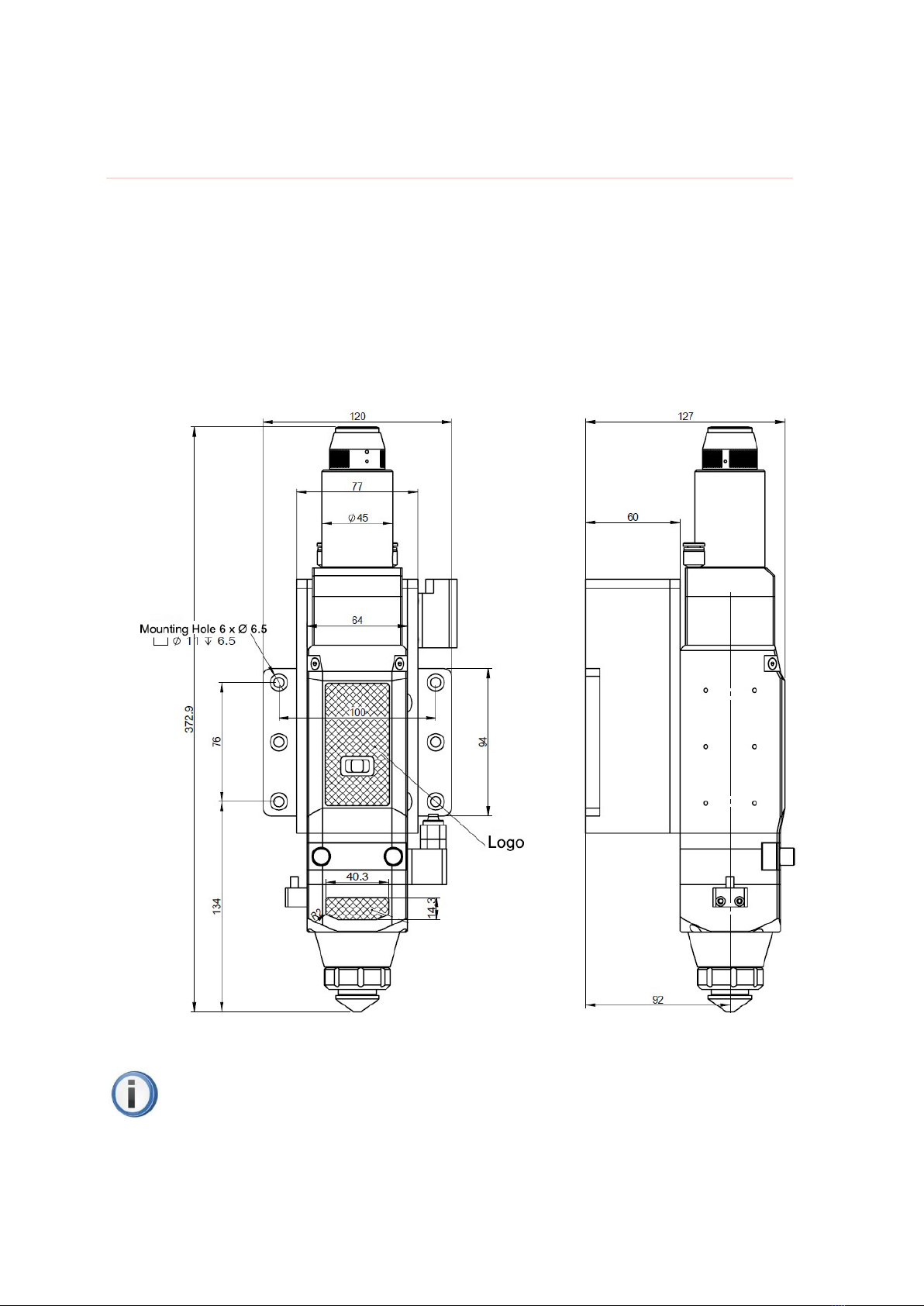
THE APPEARANCE OF A200E ELECTRIC FIBER LASER CUTTING HEAD............................................................................ 6
INSTALLATION OF MECHANICAL PARTS........................................................................................... 7
INSTALLATION OF MAIN PARTS ............................................................................................................................................... 7
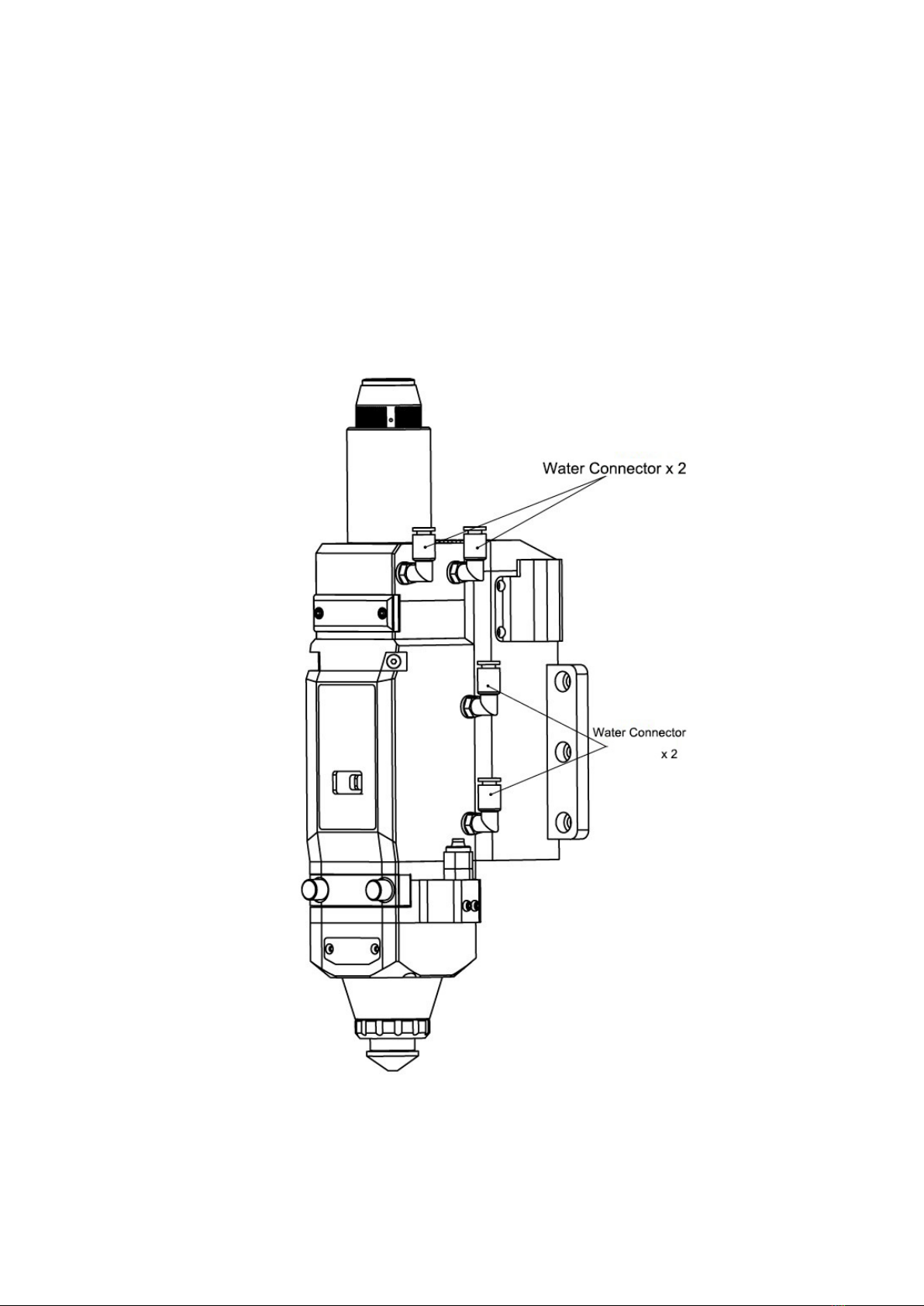
INSTALLATION OF WATER COOLING ..................................................................................................................................... 8
INSTALLATION OF GAS CIRCUIT............................................................................................................................................... 9
FIBER SOCKET ........................................................................................................................................................................... 10
THE INSERTION AND LOCKING OF QBH FIBER ................................................................................................................. 11
INSTALLATION OF ELECTRICITY AND GAS .......................................................................................................................... 12
THE CENTERING AND ADJUSTMENT OF LASER BEAM ................................................................ 14
THE CENTERING OF LASER BEAM ......................................................................................................................................... 14
FOCUS ADJUSTMENT ................................................................................................................................................................ 15
CARE AND MAINTENANCE ................................................................................................................... 17
OPTICAL LENS CLEANING ...................................................................................................................................................... 17
DISASSEMBLY AND INSTALLATION OF OPTICAL LENS: ...................................................................................................... 18
REPLACEMENT OF CAPACITIVE NOZZLE BODY .................................................................................................................. 22
COLLIMATE LENS UNIT AND FOCUS LENS UNIT OF A200E ELECTRIC FIBER LASER CUTTING HEAD. ...................... 23

2 / 23
Abstract
Key points
This user’s manual contains basic installation, factory settings, operation, maintenance
instructions and other descriptions of A200M fiber laser cutting head. Since mechanical parts
are too many, this manual will only introduce the main units.
A200E electric fiber laser cutting head, German brand A-cutter series, is designed for
laser power within 2000w, which is a wonderful solution for medium power of laser flat auto
focus cutting when working with motion control card MCC series and cutting software SC
series.
Reader Objects
This document mainly is applicable to the following personnel:
Installation engineers
Maintenance engineers
Operators
Modification Records
Modification records accumulate the descriptions of the updating of the document. The
latest version includes the updating contents of previous versions.
Version V1.0 of Document (May, 2018)
Initial release.

3 / 23
Introduction
This user’s manual contains basic installation, factory settings, operation, maintenance
instructions and other descriptions of A200M fiber laser cutting head. Since mechanical parts are too
many, this manual will only introduce the main units.
A200E electric fiber laser cutting head was designed for flat cutting within 2000w by German
brand A-cutter in 2018. With motor driver unit inside, the position of focus lens unit in z axis can be
adjust automatically in the range of 18mm, so user can set “continues focus adjustment” in the cutting
software to accelerate the thick metal plate cutting speed and cut different metal plat with different
thickness and kind. With optical lens group in D30 and multi interfaces design, A200E fiber laser
cutting head can be matched with different types of fiber laser sources. It’s much more stable during
longtime working in high laser power with its optimized optical system and water cooling system.
Product highlights
A200E electric fiber laser cutting head has been integrated with the controlling unit for
adjusting the focus lens unit’s position in z axis. By interacting with the motion control system
in Ethernet, it’s much easier for installing and adjusting the motion control system.
Adapting with light alloy materials and compact structure design, A200E electric fiber laser
cutting head has only 62mm in length and 3.5 kg in weight, which has largely reduced the
load-bearing demands on the transom of the laser cutting machine so it can be used more
widespread.
By working with SC series fiber laser cutting system, A200E can realize high speed drilling
and auto adjust different types of cutting parameters that have been set in the cutting software
in advance. Cutting software can monitor the focus position in real time and at the same time
it supports manual adjustment to achieve the perfect cutting performance.
Structure
From figure 1, we can see that A200E fiber laser cutting head contains six basic units: QBH
interface, collimate unit, focus unit, protection unit, nozzle tips unit and motor driver unit.

4 / 23
Figure 1. The structure of A200E electric fiber laser cutting head.
Fiber socket: Connect with fiber laser source.
Collimate unit: turn the incident laser beam into parallel beam,which can be adjust for
centering the laser beam.
Focus unit: turn the parallel beam into gathered beam with high energy, and adjust the focus
position in real time by regulating the focus unit.
Protective unit: avoid the focus lens being polluted by the dust from the surface of the metal
sheet and by the metal dregs produced during cutting which can increase the service life of
focus lens.
Nozzle tips unit: lead the gathered beam into the meal sheet and at the same time jet out
high-speed gas flow to make sure the perfect cutting quality.
Motor driver unit: adjust the position of focus lens unit in z axis.

5 / 23
Product configuration
A200E electric fiber laser cutting head was designed for flat cutting within 2000w, its
standard configuration is: A200E-Z100-F125.
Technical parameters
Parameters Value
Max Power 2000W
Fiber Socket QBH
Focus Lens Dia=30mm,F=125mm
Collimate Lens Dia=30mm,F=100mm
CA 27mm
Laser Wavelength 1064nm
Head Weight ≤3.5kg
Head Max Dia 62mm
Tip Dia 1mm-4mm
X-Y Adjust ±1mm
Z Adjust -9mm-9mm
Configuration list
Name Quantity
A200E-Z100-F125 Cutting head 1 set
Nozzle tips(Backup) 2 pcs
Protective windows(Backup) 1 pcs
PS: The list is our standard configuration.

6 / 23
The appearance of A200E electric fiber laser cutting head.
Figure 2. The appearance of A200E electric fiber laser cutting head.

7 / 23
Installation of mechanical parts
Installation of main parts
The size of installation hole of A200E showed as figure 3. Please make sure the fiber
laser cutting head is perpendicular to the metal sheet when installing and at the same time to
make sure the cutting head has been locked stably on the cutting machine for getting a stable
cutting quality.
Figure 3. The size and position of installation hole of A200M fiber laser cutting head.
PS: The Z axis motor’s slide table for fixing the cutting head must be conducted with the
cutting machine and must be in ground connection properly.

8 / 23
Installation of Water cooling
A200E electric fiber laser cutting head has two water cooling circuits, you could self-configure the
direction of water in and out. Kindly suggest you to use water cooling once the laser power is above
500w. The position and quantity of water cooling interface showed as below (Figure 4). The water
cooling interface is a closed-loop design, but the cooling water can also be provided from the external
and must be following the instructions showed as below:
Figure 4. The interface of water cooling of A200E electric fiber laser cutting head.

9 / 23
Parameters Value
The outside diameters of water cooling pipes 6mm
The minimum water velocity 1.8L/min(0.48gpm)
The water pressure of inlet 170-520kPa(30-60 psi)
The temperature of inlet ≥room temperature/>dew point
Hardness(compare with CaCO3) <250mg/liter
PH range 6 to 8
The size of particulate that allowed passing Dia<200 μm
Installation of gas circuit
The dregs like hydrocarbon and vapor contained in the cutting gas will damage the optical lens,
and fluctuate the power of gathered laser beam which will result in the differences of the cutting section
from the up to the bottom. Here are the suggested cutting gas and its purity (Figure 5). The higher the
gas purity is, the better the cutting quality of section will be.
The dregs can be filtered in the gas providing pipes while O2 and vapor can easily enter into the
optical system by permeating nonmetal parts, which is the reason why dust and hydrocarbon appear
inside the cutting head. So we kindly suggest you to use accessories in stainless steel and to use
purifier that can filter particulate minimum in 0.01 μm. And suggest you to use diaphragm pressure
gage in stainless steel, if you use diaphragm pressure gage in rubber, once the rubber aged, it can
easily react with the air inhaled by the industrial pressure gage and generate hydrocarbon. A200M
fiber laser cutting head has 1 cutting gas circuit, the outside diameter of gas pipe is 10mm. (Figure 5)
Table of contents
Popular Cutter manuals by other brands

Milwaukee
Milwaukee HEAVY DUTY M12 FCOT Original instructions

Makita
Makita DCS552 instruction manual

SignWarehouse.com
SignWarehouse.com Bobcat BA-60 user manual

Makita
Makita 4112HS instruction manual

GEISMAR STUMEC
GEISMAR STUMEC MTZ 350S manual

Hitachi
Hitachi CM 4SB2 Safety instructions and instruction manual


