AD Systems SP 10 User manual

Page 1
Doc : AM220-001E Release: 1.5 updated : October 2014
SP 10 OPERATION MANUAL
Automated Smoke Point
for
kerosene and aviation turbine fuels
Standard Test Methods:
ASTM D1322, IP 598, JIS K2537

Page 2
Doc : AM220-001E Release: 1.5 updated : October 2014
INFORMATION
Information in this document is subject to change without notice and does not represent a commitment
on the part of AD Systems.
AD Systems provides this document “as is”, without warranty of any kind, either expressed or implied,
including, but not limited to, the particular purpose.
All screenshots and reports shown in this manual are examples only.
AD Systems may make improvements and/or changes in this manual or in the product(s) and/or the
program (s) described in this manual at any time. This product could include technical inaccuracies or
typographical errors. Changes are periodically made to the information herein; these changes may be
incorporated in new editions of the publication. Reproduction of any part of this manual without express
written permission is forbidden.

Page 3
Doc : AM220-001E Release: 1.5 updated : October 2014
CAUTION
This analyzer has been carefully designed, manufactured and inspected for
quality. It has been equipped with a number of safety features.
However, the use of this analyzer may involve the handling of solvents,
chemicals, and other potentially dangerous flammable, toxic, etc. materials.
Please exercise caution when handling these materials while operating the
analyzer.
Please:
Read the operating manual
Wear proper protective clothing
Perform all suggested service procedures
Use care to prevent accidents.
The manufacturer accepts no responsibility for any damage or liability arising
from the use of analyzers.
Use of Non AD Systems Products and Accessories: defects or damage that
result from the use of Non-AD Systems branded or certified Products,
Accessories, Software or other peripheral equipment are excluded from
warranty.
Do not return the analyzer or any part to the factory without prior factory
authorization.

Page 4
Doc : AM220-001E Release: 1.5 updated : October 2014
Correct disposal of Waste Electrical and Electronic Equipment
in the end-of life
Applicable in the European Union and other European countries with separate collection systems
This product is designed for exclusive professional use by commercial companies. This
marking shown on the product or its literature, indicates that it should not be
disposed with other household wastes at the end of its working life. To prevent
possible harm to the environment or human health from uncontrolled waste disposal,
please separate this from other types of wastes and recycle it responsibly to promote
the sustainable reuse of material resources. Business users should contact the
producer or the importer and check the terms and conditions of the purchase
contract. If you have a separate agreement with your producer or your importer on
the end-of-life disposal in a way that you will care for disposal by your own, would you please ensure an
environmentally sound disposal according to the legal regulations for electric and electronic waste
equipment in your country.
This product should not be mixed with other commercial wastes for disposal.
The above WEEE-symbol is the official marking for equipment under the WEEE-scope. In some EC-
Member states "pure B2B equipment" is not necessarily marked with the waste bin symbol. To provide a
homogenous EC-wide procedure, AD Systems however uses the marking in all EC-Member states.

Page 5
Doc : AM220-001E Release: 1.5 updated : October 2014
CONTENTS
CONTENTS....................................................................................................................................................... 5
REVISIONS ....................................................................................................................................................... 6
ANALYZER UNPACKING .................................................................................................................................. 7
SP 10 ANALYZER DESCRIPTION....................................................................................................................... 8
SETUP ............................................................................................................................................................ 10
SWITCHING ON ............................................................................................................................................. 11
SWITCHING OFF ............................................................................................................................................11
MAIN MENU.................................................................................................................................................. 12
SETUP MENU.................................................................................................................................................14
System Configuration ................................................................................................................................ 14
How to set Date and Time.........................................................................................................................14
Set pre-programmed lists.......................................................................................................................... 15
Set a password ..........................................................................................................................................16
TEST PROCEDURE –CANDLE PREPARATION................................................................................................ 17
USE OF WICK INSERTION AND TRIMMING TOOLS ...................................................................................... 18
SP 10 –TEST OPERATION..............................................................................................................................19
Operation principle description ................................................................................................................ 19
Test modes ................................................................................................................................................20
Perform a TEST .......................................................................................................................................... 21
Test interruption .......................................................................................................................................23
Test sequences ..........................................................................................................................................24
SP10 –VERIFICATION SAMPLE CHECK .........................................................................................................25
RESULT SCREEN.............................................................................................................................................26
Test details ................................................................................................................................................ 26
Control buttons ......................................................................................................................................... 27
CALIBRATION ................................................................................................................................................28
Perform calibration ...................................................................................................................................28
Calibration history visualization ................................................................................................................30
Delete the calibration data........................................................................................................................30
MESSAGES DURING OPERATION.................................................................................................................. 31
RESULTS DATABASE...................................................................................................................................... 32
Results Search ...........................................................................................................................................32
Backup of results from the database ........................................................................................................ 33
REPORTING AND STORAGE OPTIONS ..........................................................................................................34
PRINTOUT..................................................................................................................................................34
Printing settings......................................................................................................................................... 35
Storage settings.........................................................................................................................................36
Network parameters ................................................................................................................................. 38
Report storage on USB in ASCII format ..................................................................................................... 40
Report screenshot storage on USB............................................................................................................40
DIAGNOSTIC..................................................................................................................................................41
FIRMWARE UPDATE...................................................................................................................................... 42
MAINTENANCE.............................................................................................................................................. 43
Lamp cleaning............................................................................................................................................43
Calibration of touch screen panel ............................................................................................................. 44
PARTS AND ACCESSORIES.............................................................................................................................46

Page 6
Doc : AM220-001E Release: 1.5 updated : October 2014
REVISIONS
Initial release: 1.0 of April 2011
Release 1.1 of May 2011
Modifications:
Section “Service” was updated with a maintenance procedure
Release 1.2 of July 2011
Modifications:
Screenshots were updated
Release 1.3 of August 2011:
Modifications:
Revision of the manual in accordance with firmware release 1.0.3.x
DATABASE section was updated with backup procedure
STORAGE SETTINGS section was updated with USB storage options
MAINTENANCE section was updated with Touch Screen Calibration procedure
Screenshots were updated
Release 1.4 of July 2012:
Modifications:
IP 598 test method number added
Release 1.5 of October 2014:
Modifications:
Revision of the manual in accordance with firmware release 1.0.4.6
New section in REPORTING AND STORAGE OPTIONS for printing options
LAN section was updated with Import Path Option
Screenshots were updated

Page 7
Doc : AM220-001E Release: 1.5 updated : October 2014
ANALYZER UNPACKING
Care in Unpacking
After unpacking, verify the unit and its accessories as well as any possible damage sustained in transit,
which must immediately brought to the attention of the carrier so that a statement of damage can be
made.
If equipment damage exists, keep the equipment, crates and packaging materials and file a claim with the
final carrier. Usually, the carrier will send an inspector to ascertain liability.
Send a copy of the claim to AD Systems or to its local distributor.
Please refer to the following website to get address details: www.adsystems-sa.com
Note: Do not return the analyzer or any part to the factory without factory authorization.
Packing list:
1 x SP 10 Instrument
1 x standard test candle with wick tube
1 x Power cord
1 x Operating manual
The various parts of the analyzer are carefully verified and tested before shipping. Nevertheless, it is
worth verifying that the equipment received corresponds to the packing list enclosed.
License notice:
The SP 10 is using a Windows XPEplatform. The license label is located inside the lower part of the
electronic cabinet under the CPU board. Please do not remove this sticker!
Page 8
Doc : AM220-001E Release: 1.5 updated : October 2014
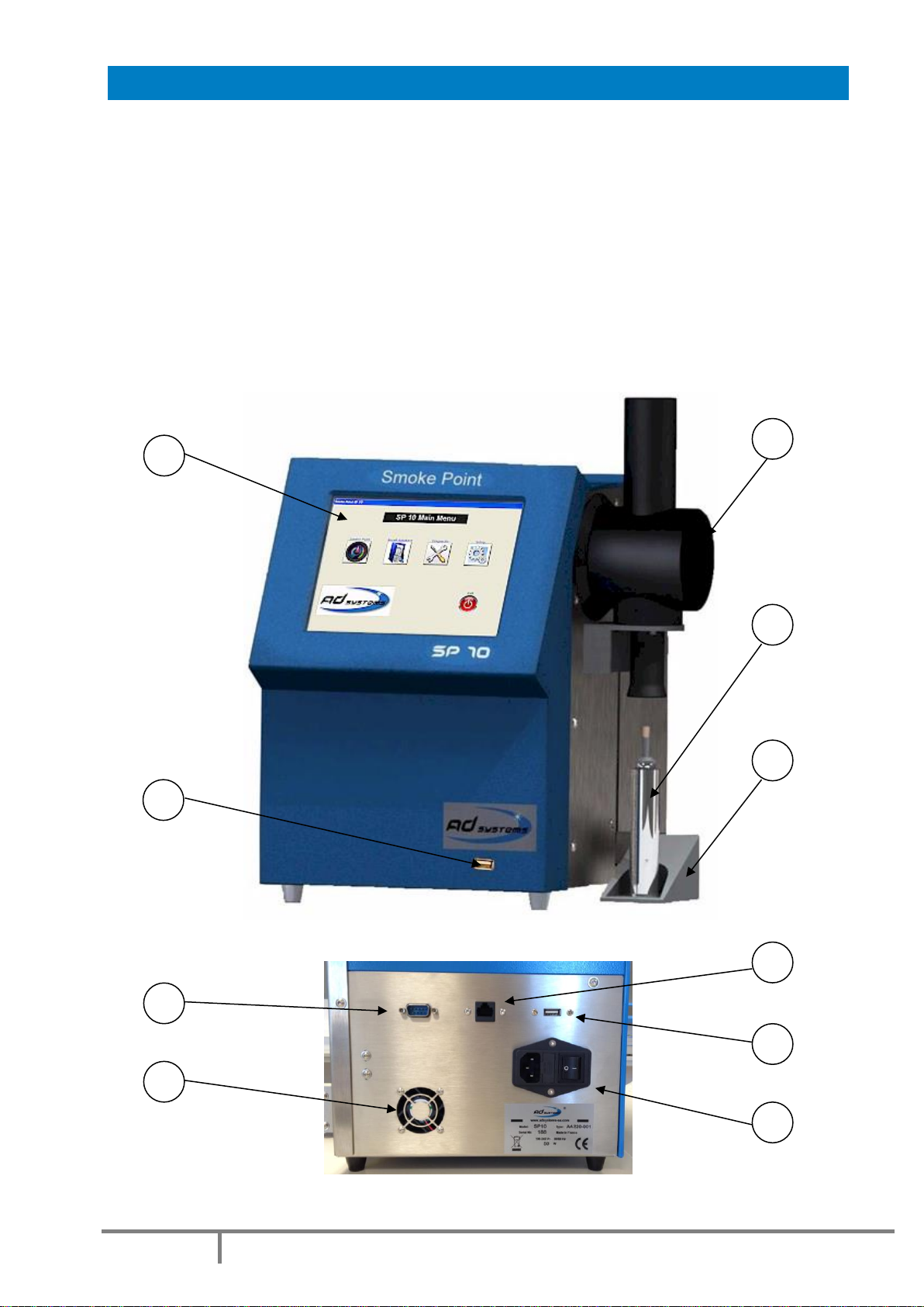
SP 10 ANALYZER DESCRIPTION
SP 10 instrument description:
1 –Full color display with touch screen
2 –Test lamp compartment
3 –Candle
4 –Candle conveyor
5 –USB port on front panel
6 –RJ45 Ethernet socket
7 –USB port on rear panel
8 –RS232 port
9 –Main switch and main power socket
10 –Cooling fan
Front view
Rear view
1
2
3
4
1
0
9
5
7
7
8
6
7

Page 9
Doc : AM220-001E Release: 1.5 updated : October 2014
Principle of the SP 10 apparatus
The SP 10 uses a patented system (License TOTAL RM) based on a video camera that observes the flame
and an actuator that adjusts the size of the flame. The flame image is digitalized and the dedicated
software analyses the shape of the flame during the test. When the flame shape corresponds to the one
described in the test method, the SP 10 memorizes the height of the flame. This specific flame is the one
with the maximum height without generating smoke. After three consecutive readings, the instrument
reports the average value corrected with the lamp factor according to the standard.
Technical specifications
Test duration
Less than 6 minutes
Resolution
0.1 mm
Results storage
Internally ; 100,000 results
Externally : Limited only to capacity of external device
LAN connectivity
Ethernet port RJ45
Printer output
Serial port (printer is optional)
Data output
USB (2), Ethernet
Dimensions (mm)
W x D x H
330 x 390 x 413 (13”x 15”x 16”)
Weight
10 kg (22 lb)
Electrical
115 to 230V - 2 A - 50/60 Hz

Page 10
Doc : AM220-001E Release: 1.5 updated : October 2014
SETUP
Install the SP 10 in an air draft free place on a horizontal flat workbench not subject to vibrations. Provide
enough space so that the analyzer can be operated conveniently. Make sure that the cooling fan on rear
panel is not obstructed and keep enough space for access to rear connectors.
Remove the touch screen protection film
Important Notices:
Install the SP 10 on a horizontal flat workbench.
oHorizontal is important! Flame goes strictly vertical at any position of the
instrument. If the SP10 unit is inclined, flame height measurement can be
erroneous.
Do not install the SP 10 under direct sunlight or under light sources
oLight beams or reflections can disturb proper operation of the flame image
detection
Protect the analyzer from air draft
oThe instrument is typically installed in a ventilated fume hood to evacuate smoke
and combustion gases. It is normal installation. But don’t close the fume hood door
that could create strong air flow. This could affect the measurement.
Make sure that the space around the motorized candle conveyor is free
oPut away any objects that could affect free movement
oWhen the conveyor goes down after the test, make sure that there is no any
objects under the conveyor.
Avoid any vibration of the instrument during the measurement.
Prevent the instrument from power supply spikes or sudden power failures.
Make sure that the cooling fan on rear panel is not obstructed and keep enough space for
access to rear connectors

Page 11
Doc : AM220-001E Release: 1.5 updated : October 2014
SWITCHING ON
CAUTION!
Once the analyzer has been unpacked, before switching-on, allow sufficient time (a few
hours) so that the analyzer adjusts to the laboratory temperature (especially if it has been
stored at low temperatures and/or at high humidity conditions).
Main Power Connection
The SP 10 analyzer operates from 100 to 240 Volts, at 50 or 60 Hz, in accordance with the majority of
countries where the analyzer is marketed.
Be sure that the main switch is OFF.
Plug the power cord provided with the SP 10 to the instrument socket , connect it to the main power
supply socket.
Press the Main Power Switch on the rear side of the analyzer to the ON position (see rear view
picture).
Verify the followings:
•The cooling fan is blowing
•The screen lights up and the Welcome Screen is displayed
•A self diagnostic test is initiated
SWITCHING OFF
In order to switch the instrument OFF, proceed always as follow:
-If a test is running, abort the test first and wait for the candle release
-Go to the Main Menu
-Press EXIT button, confirm the operation
-Wait until the screen becomes blank
-Press the Main Power Switch on the back side of the analyzer
CAUTION!
Never switch off the main switch if test is running!
Protect the instrument from sudden power supply cuts.
Page 12
Doc : AM220-001E Release: 1.5 updated : October 2014
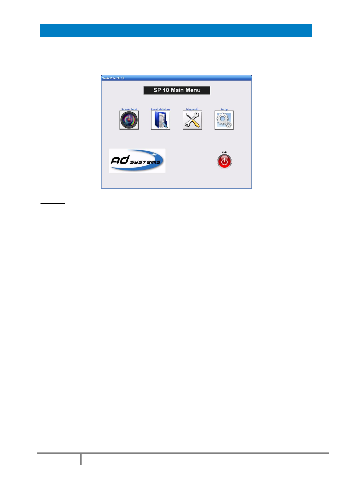
MAIN MENU
Once the SP 10 software is loaded, the instrument is ready for operation.
The Main Menu is as follow:
Buttons:
SMOKE POINT–Press this button to initiate a test operation: Test, Verification or Calibration
Refer to section: “SP 10 –Test operation” of the manual for more details.
RESULT DATABASE –to access to results archive database
Refer to section: “Results database” of the manual for more details.
DIAGNOSTIC –Service menu for maintenance and diagnostic
Refer to section: “Diagnostic” of the manual for more details
SETUP –to set or modify instrument settings, pre-program drop-down lists, reports storage options and
firmware update
Refer to section: “SETTINGS” of the manual for more details.
EXIT –to quit the SP 10 application to prepare the instrument switch off.
Refer to section: “Switching Off” of this manual for more details.

Page 13
Doc : AM220-001E Release: 1.5 updated : October 2014
The complete structure of the SP 10 software menus is as follow:
The sign means that this menu is protected by a password in order to prevent unauthorized changes
of critical instrument settings.
Factory set password is 00000 as default.
This password is active when you receive the instrument.
In order to change the password, go to the menu SETUP/Password Settings.

Page 14
Doc : AM220-001E Release: 1.5 updated : October 2014
SETUP MENU
Use the “SETUP” button of the Main Menu to access to configuration, clock settings, firmware update and
other options.
System Configuration
The SETTINGS screen provides information on the current system configuration.
In case of communication with AD Systems technical support department, this information will be
requested.
How to set Date and Time
The “Clock Settings” button allows the setting or adjustment of the date and time.
Select the date in the calendar to change the date.
Touch the Hour / Minute / Second area to change
the value.
Settings are available in 24h mode only.

Page 15
Doc : AM220-001E Release: 1.5 updated : October 2014
Set pre-programmed lists
The “List Settings” button allows entering information which will then be used in drop-down lists.
There are four sections in this menu:
To make a new entry in the list, simply press the Add button, the virtual keyboard will appear. Type-in the
data and press ENTER. To delete any record, select it and press the DEL button.
In order to memorize the modifications, press Save button prior leaving the menu.
Description of Lists:
Operators - name of the person performing tests on the SP 10. Maximum 15 characters.
Sample Type - identification of fuel type to be tested. Maximum 15 characters.
Reference Sample - identification of reference blend used for instrument calibration.
The instrument is shipped with factory pre-defined list of reference fuels in according with the ASTM
D1322 Table 1:
Mix1 T40-I60 Reference value : 14,7 cm
Mix2 T25-I75 Reference value : 20,2 cm
Mix3 T20-I80 Reference value : 22,7 cm
Mix4 T15-I85 Reference value : 25,8 cm
Mix5 T10-I90 Reference value : 30,2 cm
Mix6 T5-I95 Reference value : 35,4 cm
Mix7 T0-I100 Reference value : 42,8 cm
The reference sample name is associated with the reference value. This value will be in future used by the
instrument when the corresponding reference fuel is selected for calibration. It is not possible to delete
the factory fuels or add other fuels in the list.
Verification Sample - identification of quality control fuels used for periodical instrument verification .
Maximum 15 characters. The verification sample name is associated with control limits: Low Limit and
High Limit. Limits values should be entered in tenth of millimeters. The entry of new verification sample
without limits is not allowed.
Example: Name: CRM1; Low Limit: 235 (23,5 mm); High Limit: 245 (24,5 mm)

Page 16
Doc : AM220-001E Release: 1.5 updated : October 2014
Set a password
The access to some specific SP10 menus is password protected in order to prevent unauthorized changes
of specific critical instrument settings.
The password is a 5 digits code.
The factory set password is 00000.
This password is active when you receive the instrument.
In order to change the password, go to the menu SETUP/PASSWORD SETTINGS.
CAUTION!
When you change the password, please, record the new password, it will be not displayed!
If you forget your password, please contact AD Systems or its local distributor.

Page 17
Doc : AM220-001E Release: 1.5 updated : October 2014
TEST PROCEDURE –CANDLE PREPARATION
Test fuel:
Prepare the fuel to be tested according to the standard test method.
The fuel should be at ambient temperature.
Wick:
Wick plays a very important role in smoke point test! It is responsible for proper combustion and correct
result.
Important Notices:
-Use new wick for every test
-Use only extracted wicks, prepared according to the test method. Extract all wicks, either new or
from a previous determination, for at least 25 cycles in an extractor,
using a mixture of equal volumes of toluene and anhydrous methanol.
oSee all details of extraction procedure in the standard test
method. The extraction apparatus is available as an additional
accessory; please refer to “Parts and Accessories” section of
the manual.
-Keep wicks away from humidity. If you hear some crackle sounds
during the test, it means the wick is humid.
-If the wick is not well prepared, the flame is unstable (of course, in
absence of the air draft around the instrument, which is another factor
of flame instability)
-The wick should be not too long and not too short. Maximum length is
140mm (practical reason, more longer wick cannot be inserted into the
candle) and minimum 125mm (method requirement)
-The cotton wick structure and textile specification are very well
defined in the test method. To obtain right measurements use only
wicks conforming to the standard requirements.
oAD Systems is the supplier of the wicks conforming to the
ASTM D1322 specification.
Candle:
Soak a piece of extracted and dried wick, not less than 125 mm long, in the sample and place it in the wick
tube of the candle. It is advisable to re-soak the burning-end of the wick in the sample after the wick is
inserted in the wick tube.
A wick-trimmer is available as an additional accessories (refer to “Parts and Accessories” section of the
manual).
It is advised to use a wick-trimmer assembly for the insertion of the wick in the wick tube; this will avoid
twists and frayed ends. See next section of the manual for instructions.
Pour between 10 to 20ml of the prepared sample at room temperature into a clean and dry candle. The
wick tube with the prepared wick is then inserted into the candle and screwed home.
Important Notices:
Use only candles supplied by AD Systems for the SP10 apparatus
Be sure that wick is cut horizontally, it has not frayed ends and the wick tip is perfectly straight
to the candle axis.
Make sure that the candle air vent at the bottom is not obstructed and free of fuel.
Page 18
Doc : AM220-001E Release: 1.5 updated : October 2014
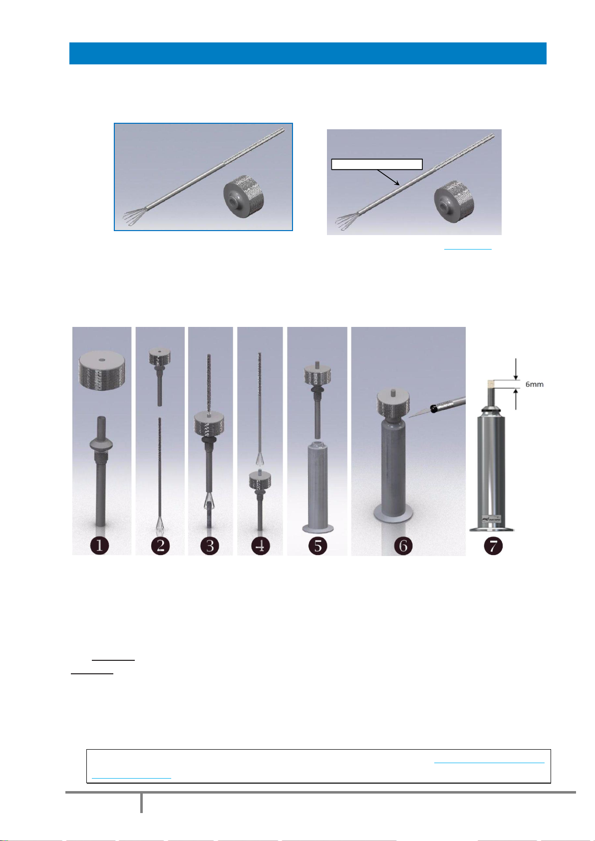
USE OF WICK INSERTION AND TRIMMING TOOLS
The “Wick Insertion Tool” (part number: AK220-001) consists of two parts:
1. Wick Insertion Tong (Top)
2. Wick Trim Gauge (Bottom).
Please note that the wick insertion tong is available separately as P/N ST220-004
Instructions:
This tool saves a significant amount of time in test preparation, avoids twisting of the wick and fraying of
ends. It is easy and straightforward to use.
1. Place the wick trim gauge on the top of the wick tube
2. Insert the tongs into the wick tube
3. Grip the top of the wick after it has been properly soaked in the sample according to the method
4. Gently pull the tongs with grasped wick through the wick gauge
5. When the wick is in place, keep the trim gauge on the wick tube and screw the assembly to the
candle filled with the sample according to the method
6. CAUTION: Use care when handling a sharp blade or knife!
CAUTION: Some new blades have a protective coating; remove the coating with a solvent before use
Using a clean sharp blade or knife, trim the wick level with the top of the trim gauge. Before
removing the trim gauge, thoroughly inspect the trimmed wick tip to ensure there are no frayed ends
or rough edges. Remove any frays or edges with a sharp blade or knife.
7. Remove the trim gauge. The candle is now ready for testing.
For more details, please note that a video is available on our website: http://www.adsystems-
sa.com/sp10.php
AK220-001 - SET OF TOOLS FOR WICK INSERTION AND TRIMMING
ST220-004 - Tong for wick trimmer

Page 19
Doc : AM220-001E Release: 1.5 updated : October 2014
C
SP 10 –TEST OPERATION
Operation principle description
The smoke point test with the SP 10 is as simple as is an automated flash point test.
Phase 1.The operator prepares the
candle according to the test method
instructions (see the section “Test
procedure –Candle preparation”
above);
Phase 2. The candle is then positioned
on the conveyor of the analyzer
Phase 3.The operator keys in all sample
details and then initiate the test
Then all the procedure is automated.
The candle is automatically lit, the five
minutes stabilization time is followed
by the three readings of the flame
height
Definition of smoke point given by the standard:
The test method procedure requires to raise the candle until a smoky tail appears, then lower the candle
slowly through the following stages of flame appearance:
Smoky flame - A long tip; smoke slightly visible; erratic and jumpy flame.
Flame A - An elongated, pointed tip with the sides of the tip appearing concave upward
Flame B - The pointed tip just disappears, leaving a very slightly blunted flame. Jagged,
erratic, luminous flames are sometimes observed near the true flame tip. These shall be
disregarded.
Flame C - A well rounded tip
The smoke point value corresponds to the height of flame B.
The SP10 software analyses flame images taken by digital camera and automatically detects the flame
shape corresponding to the flame B according the standard.

Page 20
Doc : AM220-001E Release: 1.5 updated : October 2014
At the end of test, the SP 10 instrument calculates the mean value of the three consecutive readings of
the smoke point. The result is rounded then corrected with the memorized lamp correction factor. A
complete test report is saved in a built‐in data base. It can be printed, transferred on a USB memory stick
and/or send to a LIMS when the SP 10 is connected to a LAN.
Test modes
Press the “TEST” button on the Main menu.
By pressing corresponding button on the top of the screen, select type of measurement to perform:
TEST –test sample measurement mode
VERIFICATION –proceed with measurement of verification sample for periodic instrument check
CALIBRATION –proceed with lamp factor calibration by reference fuels
Depends on the mode of measurement, the required test information fields will change accordingly.
Check that the instrument is ready for test –status should be “Ready”.
Table of contents
Other AD Systems Test Equipment manuals


