AD Systems Deposit Rater DR10 User manual

Page 1
Doc : AM210-001E Release: 1.4 updated : 2015
DR10 OPERATION MANUAL
Deposit Rater
for
Thermal Oxidation of Aviation Turbine Fuels
Measurement of Deposit Tickness
On Heater Tubes
ASTM D3241 –Annex 2 ITR

Page 2
Doc : AM210-001E Release: 1.4 updated : 2015
INFORMATION
Information in this document is subject to change without notice and does not represent a commitment
on the part of AD systems.
AD systems provides this document “as is”, without warranty of any kind, either expressed or implied,
including, but not limited to, the particular purpose.
All screenshots and reports shown in this manual are examples only.
AD systems may make improvements and/or changes in this manual or in the product(s) and/or the
program (s) described in this manual at any time. This product could include technical inaccuracies or
typographical errors. Changes are periodically made to the information herein; these changes may be
incorporated in new editions of the publication. Reproduction of any part of this manual without express
written permission is forbidden.

Page 3
Doc : AM210-001E Release: 1.4 updated : 2015
CAUTION
This analyzer has been carefully designed, manufactured and inspected for
quality. It has been equipped with a number of safety features.
However, the use of this analyzer may involve the handling of solvents,
chemicals, and other potentially dangerous flammable, toxic, etc. materials.
Please exercise caution when handling these materials while operating the
analyzer.
Please:
Read the operating manual
Wear proper protective clothing
Perform all suggested service procedures
Use care to prevent accidents.
The manufacturer accepts no responsibility for any damage or liability arising
from the use of analyzers.
Use of Non AD systems Products and Accessories: defects or damage that result
from the use of Non-AD systems branded or certified Products, Accessories,
Software or other peripheral equipment are excluded from warranty.
Do not return the analyzer or any part to the factory without prior factory
authorization.

Page 4
Doc : AM210-001E Release: 1.4 updated : 2015
Correct disposal of Waste Electrical and Electronic Equipment
in the end-of life
Applicable in the European Union and other European countries with separate collection systems
This product is designed for exclusive professional use by commercial companies. This
marking shown on the product or its literature, indicates that it should not be
disposed with other household wastes at the end of its working life. To prevent
possible harm to the environment or human health from uncontrolled waste disposal,
please separate this from other types of wastes and recycle it responsibly to promote
the sustainable reuse of material resources. Business users should contact the
producer or the importer and check the terms and conditions of the purchase
contract. If you have a separate agreement with your producer or your importer on
the end-of-life disposal in a way that you will care for disposal by your own, would you please ensure an
environmentally sound disposal according to the legal regulations for electric and electronic waste
equipment in your country.
This product should not be mixed with other commercial wastes for disposal.
The above WEEE-symbol is the official marking for equipment under the WEEE-scope. In some EC-
Member states "pure B2B equipment" is not necessarily marked with the waste bin symbol. To provide a
homogenous EC-wide procedure, AD systems however uses the marking in all EC-Member states.

Page 5
Doc : AM210-001E Release: 1.4 updated : 2015
CONTENTS
CONTENTS....................................................................................................................................................... 5
APPLICATION................................................................................................................................................... 7
TURBINE FUELS THERMAL OXIDATIONTEST ..........................................................Erreur ! Signet non défini.
DR10 TECHNICAL DESCRIPTION...................................................................................................................... 9
ANALYZER UNPACKING ................................................................................................................................ 10
ANALYZER DESCRIPTION ..............................................................................................................................11
SETUP ............................................................................................................................................................ 13
SWITCHING ON ............................................................................................................................................. 13
SWITCHING OFF ............................................................................................................................................ 13
MAIN MENU..................................................................................................................................................14
SETUP MENU................................................................................................................................................. 16
System Configuration ................................................................................................................................ 16
How to set Date and Time.........................................................................................................................16
Set pre-programmed lists.......................................................................................................................... 17
Set password ............................................................................................................................................. 17
System Information Ticket ........................................................................................................................18
Calibration of touch screen panel ............................................................................................................. 19
DEPOSIT RATING –TEST OPERATION...........................................................................................................20
RESULTS REPORTED ......................................................................................................................................24
Test results ................................................................................................................................................24
Test information........................................................................................................................................25
Control buttons ......................................................................................................................................... 25
Additional Result information –button MORE .........................................................................................26
Test report –Particular case .....................................................................................................................27
TEST OPERATION with User Defined Matrix................................................................................................28
Set the User Defined Matrix...................................................................................................................... 28
Start a test with User Defined Matrix ....................................................................................................... 29
RESULTS DATABASE......................................................................................................................................31
Results Search ...........................................................................................................................................31
RESULTS EXPORT........................................................................................................................................... 33
LAN data storage ....................................................................................................................................... 34
Network parameters ................................................................................................................................. 36
USB data storage.......................................................................................................................................38
REPORT PRINTOUT .......................................................................................................................................39
BASELINE CALIBRATION................................................................................................................................40
VERIFICATION ...............................................................................................................................................42
DIAGNOSTIC.................................................................................................................................................. 44
MESSAGES DURING TEST OPERATION ......................................................................................................... 45
DOOR OPEN............................................................................................................................................... 45
TUBE NOT DETECTED................................................................................................................................. 45
TEST INTERRUPTION..................................................................................................................................45

Page 6
Doc : AM210-001E Release: 1.4 updated : 2015
OTHER MESSAGES ..................................................................................................................................... 46
FIRMWARE UPDATE...................................................................................................................................... 47
SERVICE ......................................................................................................................................................... 48
Revisions .......................................................................................................................................................49
Page 7
Doc : AM210-001E Release: 1.4 updated : 2015
APPLICATION
The Jet Fuel Thermal Oxidation Test ASTM D3241 is universally used by the industry to measure high
temperature stability of aviation turbine fuels. The ASTM D3241 is required to be run on every batch of Jet Fuel
produced according to ASTM D1655 or DEF STAN 91-91 specifications. In this test method the fuel is pumped
through heater tube at fixed flow rate and during a specified period of time. The fuel is pass or fail rated
according to the amount of deposit formed on the heater tube at specified temperature.
Traditionally the amount of deposit on the tube is rated visually by the operator against reference color
scale. The proper rating requires significant experience and expertise. But operator capabilities vary, so
evaluation of color can be quite subjective.
Many articles have been published on the fact that color does not provide real information on the thickness
and volume of deposits, parameters which are far more meaningful for characterizing jet fuels for users and
suppliers. The aviation fuel industry found that one of the most crucial stage of this test method is an
objective analysis of deposit produced on the heater tube.
A new instrumental method of quantitative measurement of tube deposits has been developed by AD
Systems, in which the thickness of the deposit is accurately determined by an automatic instrument,
reducing test subjectivity. The technique is described in ASTM D3241 –Annex 2 ITR, Interferometry Tube
Rating.
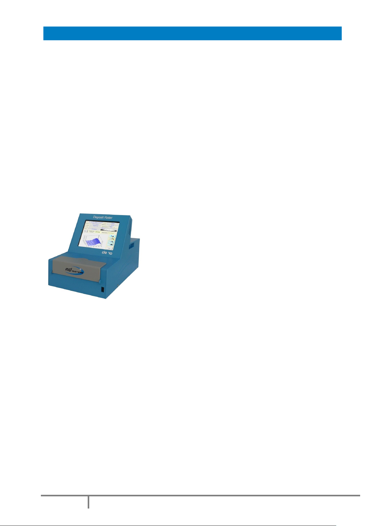
The innovative DR10 instrument uses interferometry technique for
precise measurement of deposit thickness in nanometers range. This
stand alone compact instrument can be easy installed at any location
ideal for workflow. The operation is based on a powerful light source,
a spectrometer with a fiber optic probe and specially
designed application software.
The DR10 use is simple and straightforward. The heater tube is
prepared according to ASTM D3241 test procedure and is then
placed in the test chamber of the DR10. Using intuitive graphical
interface with touch screen panel, the operator enters sample
information and start a tube scan. Specific light is emitted on the surface of the heater tube. The reflected
light is collected and the interference created by the deposit is monitored by the spectrometer. The built-in
software analyzes the interference fringes and calculates the deposit thickness. The mechanical system
displaces the optical probe and rotates the heater tube taking precise thickness measurements at 1,200
points along and around its surface. The detailed test report is ready in less than 15 minutes including 3D
profile of the deposit distribution on the tube surface.
The software automatically detects and report the Standard Spot value which is mean deposit thickness of
the thickest 2.5 mm2area as defined in the ASTM D3241. In addition, the average and the maximum
thickness deposit values, as well as the calculated total deposit volume are reported. For complete test
traceability, the DR10 report is tagged with the heater tube serial number picture taken by a built-in
camera.
The DR 10 is essentially useful measurement tool for fuel research programs providing unique information
on fuel deposit behavior at different oxidation temperatures and for evaluation of antifouling additives
efficiency. The DR 10 is versatile instrument for research and routine applications at every location where
thermal oxidation of turbine fuel is evaluated:
Refineries
Pipelines and terminals
Airports
Military (field labs)
Research labs
Third party labs
Page 8
Doc : AM210-001E Release: 1.4 updated : 2015
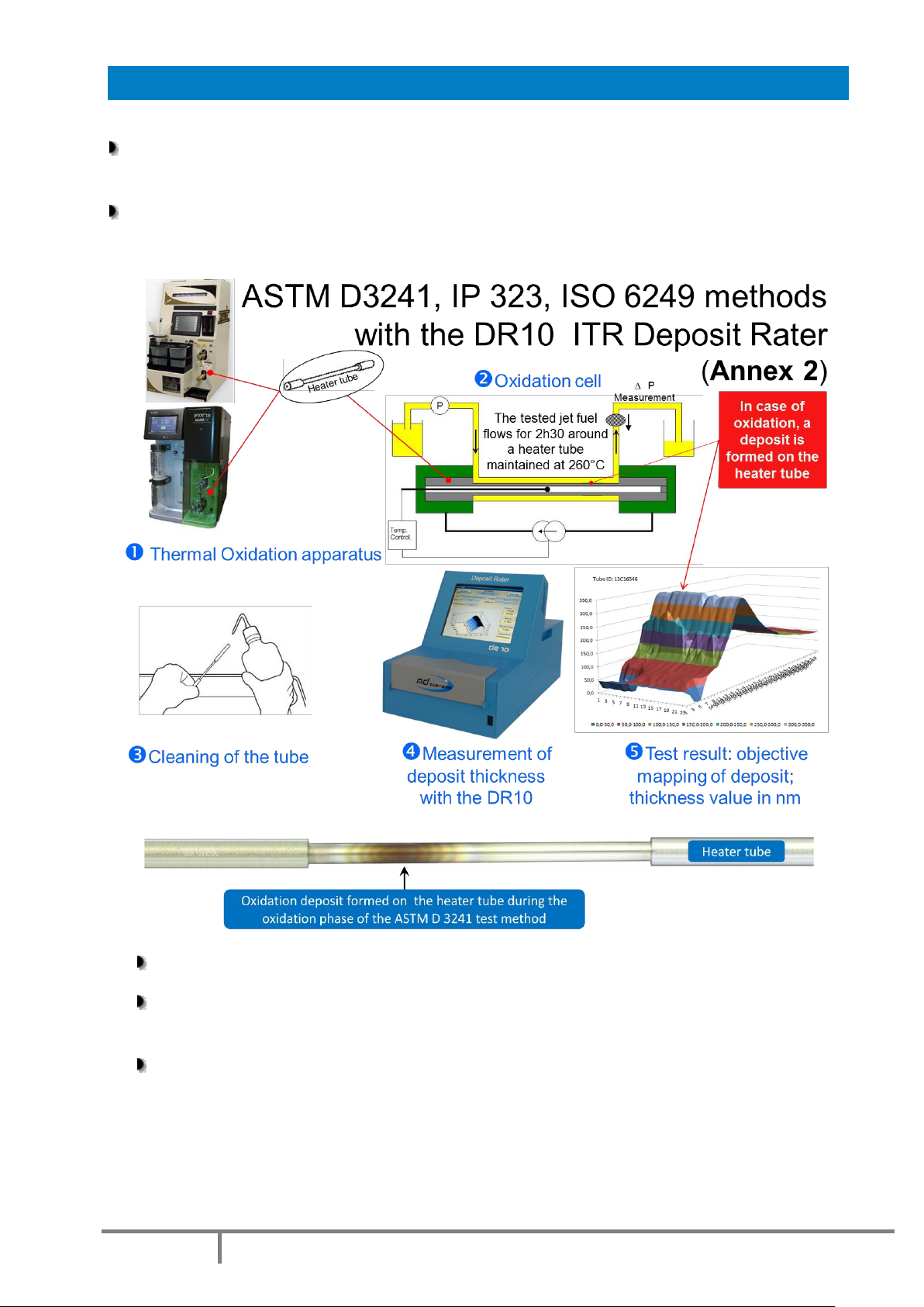
TURBINE FUELS THERMAL OXIDATION TEST
The ASTM D 3241 is a standard test required to be run on every batch of jet fuel produced according
to ASTM D1655 or DEF STAN 91-91 specifications
In this test method, the fuel is pumped during a specified period of time at fixed flow rate over an
aluminum tube heated at a specified temperature.
The aluminum heater tube is extracted and cleaned
The fuel is then pass or fail rated according to the thickness of the deposit measured by the DR10
–ITR on the heater tube
Jet Fuel international specifications (ASDTM D1655, ASTM D7566 and Def Stan 91-01) indicate a
85 nm average over an area of 2.5 mm2as a PASS limit.

Page 9
Doc : AM210-001E Release: 1.4 updated : 2015
DR10 TECHNICAL DESCRIPTION
The DR 10 uses fiber optic interferometry technique.
Broadband wavelength light is emitted on the surface of the heater tube via an optical probe.
The reflected light is collected and the interference created by the deposit is processed by
the spectrometer.
The software analyzes the interference fringes and calculates the deposit thickness
The full scan of tube surface on 1,200 points is completed in less than 15 minutes.

Page 10
Doc : AM210-001E Release: 1.4 updated : 2015
ANALYZER UNPACKING
Care in Unpacking
After unpacking, verify the unit and its accessories as well as any possible damage sustained in transit,
which must immediately brought to the attention of the carrier so that a statement of damage can be
made.
If equipment damage exists, keep the equipment, crates and packaging materials and file a claim with the
final carrier. Usually, the carrier will send an inspector to ascertain liability. Send a copy of the claim to AD
systems or to its local distributor.
Please refer to the following website to get address details: www.adsystems-sa.com
Note: Do not return the analyzer or any part to the factory without factory authorization.
Packing list:
1 x DR 10 Instrument
1 x Power cord
1 x Operating manual
The various parts of the analyzer are carefully verified and tested before shipping. Nevertheless, it is
worth verifying that the equipment received corresponds to the packing list enclosed.
Page 11
Doc : AM210-001E Release: 1.4 updated : 2015
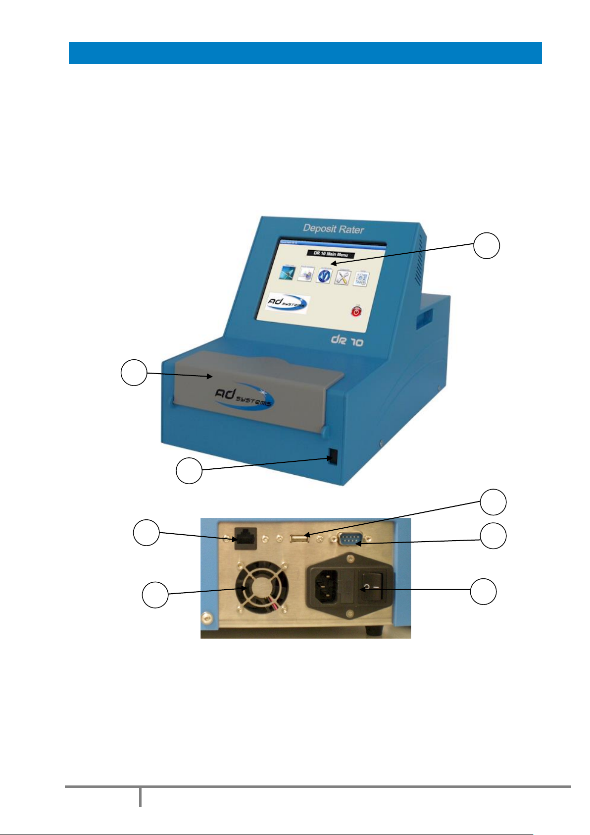
ANALYZER DESCRIPTION
The DR 10 instrument presents as follow:
1 –Full color display with touch screen
2 –Test compartment
3 –USB port on front panel
4 –RJ45 Ethernet socket
5 –Cooling fan
6 –Main switch and main power socket
7 –USB port on rear panel
8 –RS232 port
Front view
Rear view
Main Power Connection
The DR 10 analyzer operates from 100 to 240 Volts, at 50 or 60 Hz, in accordance with the majority of
countries where the analyzer is marketed. Plug the power cord to the instrumentand to the main plug.
1
2
3
4
5
6
7
8
7

Page 12
Doc : AM210-001E Release: 1.4 updated : 2015
DR10 test compartment:
9 –Heater tube supports
10 –Optical probe protection cover
11 –Digital camera for tube serial number identification
12 –Door lock switch
13 - Test compartment cover
License notice:
The DR 10 is using a Windows XPEplatform. The license label is located inside the lower part of the
electronic cabinet under the CPU board. Please do not remove this sticker!
11
10
7
9
7
13
12

Page 13
Doc : AM210-001E Release: 1.4 updated : 2015
SETUP
Put the DR 10 on a horizontal flat workbench and not subject to vibrations, near electrical sockets.
Provide enough space so that the analyzer can be operated conveniently and for access to the rear
connectors.
Remove the touch screen protection film
Note:
Do not install the DR 10 under direct sunlight.
Put the analyzer away from strong lighting sources; it can affect the measurement.
Leave sufficient space behind the analyzer for clear ventilation.
Do not cover the air intake slots of the unit. Failure of sufficient air ventilation could cause
instrument damage.
SWITCHING ON
CAUTION!
Once the analyzer has been unpacked, before switching-on, allow sufficient time (a few
hours) so that the analyzer adjusts to the laboratory temperature (especially if it has been
stored at low temperatures and/or at high humidity conditions).
Press the Main Power Switchon the back side of the analyzer to the ON position (see rear view picture).
Verify the followings:
•The cooling fan is starting
•The screen lights up and the Welcome Screen is displayed
•A self diagnostic test is initiated
SWITCHING OFF
In order to switch the instrument off, proceed as following:
-If a test is running, abort the test first
-Go to the Main Menu
-Press EXIT button
-Wait until the screen becomes blank
-Press the Main Power Switch on the back side of the analyzer
CAUTION!
Never switch off the unit if test is running!

Page 14
Doc : AM210-001E Release: 1.4 updated : 2015
MAIN MENU
Once the DR 10 application is loaded, the instrument is ready for deposit thickness measurement.
The Main Menu is as follow:
Buttons:
TUBE SCAN –Press this button to initiate a deposit rating test
Refer to section: “Deposit Rating – Test operation” of the manual for more details.
RESULT DATABASE –to access to results archive database
Refer to section: “Results database” of the manual for more details.
VERIFICATION –verification of the instrument with reference thickness tubes
Refer to section: “Verification” of the manual for more details.
DIAGNOSTIC –Service menu for maintenance and diagnostic
Refer to section: “Diagnostic” of the manual for more details
SETUP –to set or modify instrument settings, pre-program drop-down lists, reports storage options and
instrument calibration
Refer to section: “SETTINGS” of the manual for more details.
EXIT –to quit the DR10 application to prepare the instrument switch off.
Refer to section: “Switching Off” of this manual for more details.

Page 15
Doc : AM210-001E Release: 1.4 updated : 2015
The complete structure of the DR10 menus is shown on the following diagram:
Sign means that this menu is protected by a password in order to prevent unauthorized changes of
critical instrument settings.
Factory set password is 00000 as default.
This password is active when you receive the instrument.
In order to change the password, go to the menu SETUP/Password Settings.

Page 16
Doc : AM210-001E Release: 1.4 updated : 2015
SETUP MENU
Use the “SETUP” button of the Main Menu to access to configuration, clock settings, firmware update and
other options.
System Configuration
The SETTINGS screen provides information on current system configuration.
In case of communication with AD Systems technical support department, this information will be
requested.
How to set Date and Time
The “Clock Settings” button allows setting or changing the date and time.
Select the date in calendar to change the date.
Touch the Hour / Minute / Second area to change
the value.
Settings are available in 24h mode only.

Page 17
Doc : AM210-001E Release: 1.4 updated : 2015
Set pre-programmed lists
The “List Settings” button allows entering information which future will be used in drop-down lists.
There are five sections in this menu:
Operators - identification of the person performing the test. Maximum 15 characters.
Sample Type - identification of jet fuel type for reporting. Maximum 15 characters.
Temperature - the test temperature (in °C) of jet fuel oxidation in thermal oxidation stability rig during
D3421 test. Maximum 3 digits.
Test Rig ID - identification of the thermal oxidation stability rig. Maximum 15 characters.
Touch the entry area and the virtual keyboard will appear.
Type-in the data for each field and press ENTER.
Press Add button to add any data in the list.
If you want to delete a data already entered, select this data and press Del button.
In order to memorize the modifications, press SAVE button prior leaving the menu.
User Defined Steps Numbers –Please see the “TEST OPERATION with User Defined Matrix”Section.
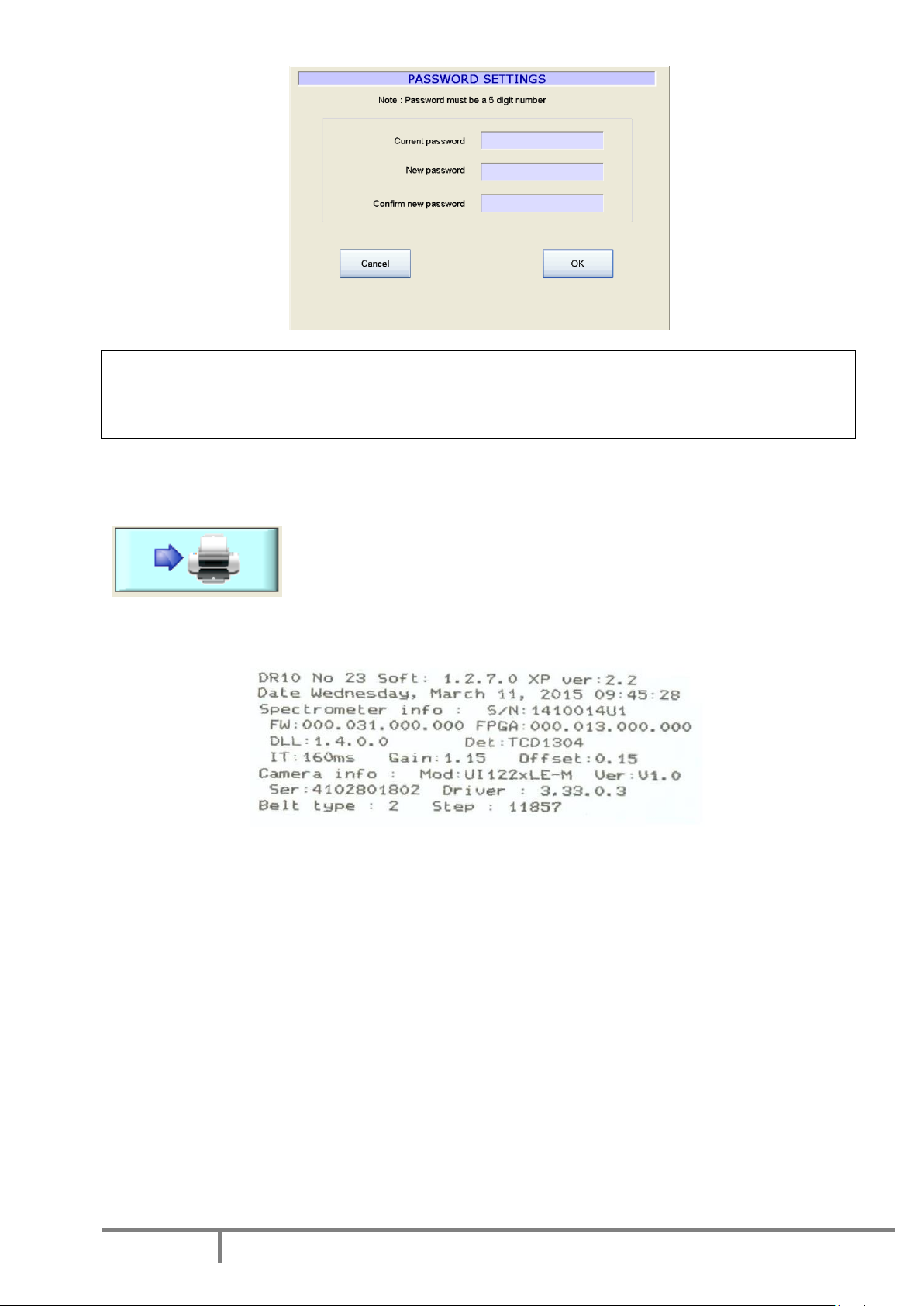
Set password
The access to specificDR10menus is password protected in order to prevent unauthorized changes of
critical instrument settings.
The password is a 5 digits code.
The factory set password is 00000.
This password is active when you receive the instrument.
In order to change the password, go to the menu SETUP/PASSWORD SETTINGS.
Page 18
Doc : AM210-001E Release: 1.4 updated : 2015
CAUTION!
When you change the password, please, record the new password, it will be not displayed!
In case if you forget your password, please contact AD systems or its local distributor.
System Information Ticket
Click on this button to print a ticket with all system’s informations.
Ticket Example

Page 19
Doc : AM210-001E Release: 1.4 updated : 2015
Calibration of touch screen panel
In case of repair or replacement of the touch screen, it needs to be calibrated.
A special function in the menu SETTINGS facilitates this operation.
Press “Touch Screen Calibration” button.
If the touch panel is fully misadjusted and it is not possible to use touch screen, connect an USB mouse to
the USB port of the instrument and use the mouse to access to the menu.
To calibrate the touch screen use a pointing device like a stylus.
In the calibration mode, touch the center of each cross which will appear on the screen.
After consequently touching calibration crosses in the 4 corners of the screen, the menu asks for
confirmation of the calibration by touching the CONFIRM button in the center of the screen.
Attention!
If you see that calibration is not successful (you mismatched a cross), don’t confirm it!
Don’t press Confirm button.
Just wait 10 seconds, the CT10 menu will re-appear.
Press “Touch Screen Calibration” button and repeat the calibration properly.
Page 20
Doc : AM210-001E Release: 1.4 updated : 2015
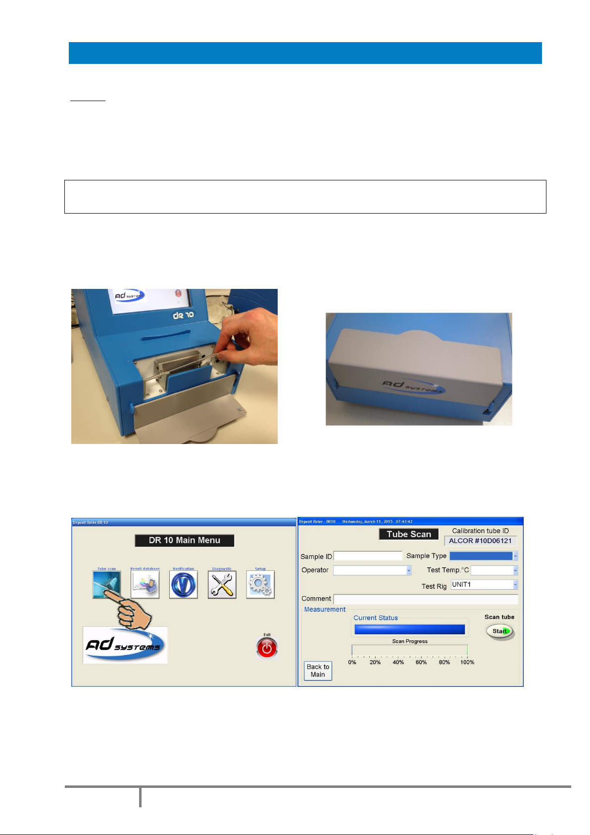
DEPOSIT RATING –TEST OPERATION
Note: prior the rating of the heater tube, it is important to make sure that the heater tube has been
prepared according to the instructions mentioned in the ASTM D 3241, IP 323 or ISO 6249 test method.
Open the door of the DR 10 test compartment
Take a heater tube ready to be rated.
Caution! Handle the heater tube carefully; finger print will affect the result, never touch the center
portion at any time
Identify the location of the tube serial number.
Carefully place the heater tube on the support. The tube serial number must be located on the right hand
side.
Close the test compartment door.
Press the “Tube Scan” button on the Main menu.
The Tube Scan menu will be displayed.
In order to initiate the measurement, the information described here after must be entered. All fields are
mandatory with exception of the “Comment” field which is optional.
Table of contents
Other AD Systems Test Equipment manuals

Popular Test Equipment manuals by other brands

INNOVATEST
INNOVATEST FALCON500 manual

Würth
Würth PRO II LCD Translation of the original operating instructions

DARKSTAR TECHNOLOGIES
DARKSTAR TECHNOLOGIES D220 Guide to Operation

yellow jacket
yellow jacket RecoverX Operation and maintenance manual

Joy-it
Joy-it DSO-138-MINI quick start guide

Phenix
Phenix LD60A user manual


