EMTEST PFM 200N200 User manual
User’s Guide
PFM 200N100.1
PFM 200N200
Voltage Dips and Drops Interruptions
- E-10 Brief Voltage Drop
- E-13 Dropout Pin
- E-14 Dropout Connector
- E48-09 Short Interruptions
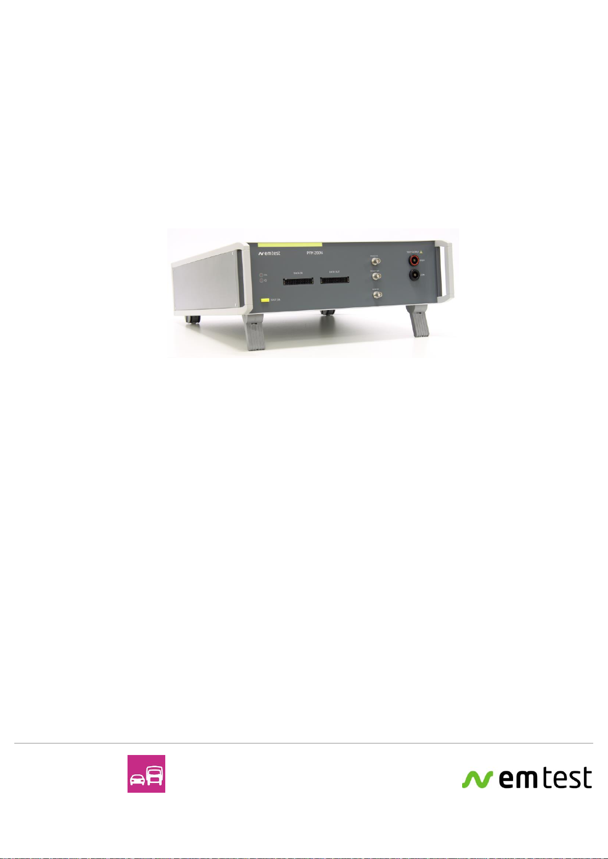
The PFM 200N Series has been specially engineered for
performing dropout pulses on battery and signal lines.
The PFM 200N contains a switch for battery voltage as well as
additional switches for battery return lines from 100 mA up to
100 A or 200 A depending on the model. An additional set of 16
switches are provided for data and signal line switching from
100 μA to 2 A.
BMW QV65013
GMW3172
LV 124 (2013)
LV 148
Renault 36-00-808/--M
Nissan 28401 NDS02
Version:
1.21 / 29.6.2020
emc test equipment
Replaces:
1.20 / 11.6.2020
File Name:
UserManual-PFM200Nx-E-V1.21.doc
Print Date:
29.06.20


EM TEST PFM 200N Series
User’s Guide Ver. 1.21 3 / 45
Contents
1. Introduction....................................................................................................................................................5
1.1. Overview............................................................................................................................................5
2. Safety..............................................................................................................................................................6
2.1. Safety Instructions .............................................................................................................................6
2.2. Care During Testing...........................................................................................................................7
2.2.1. Switching Off ............................................................................................................................................7
2.2.2. Danger to the Device Under Test (DUT) .................................................................................................7
2.2.3. Input Capacitance ....................................................................................................................................7
3. Package Contents and Putting Into Service...............................................................................................8
3.1. Basic Equipment PFM 200N100.1 ....................................................................................................8
3.2. Basic Equipment PFM 200N200........................................................................................................8
3.3. Accessories........................................................................................................................................8
3.4. Options PFM 200N100.1 ...................................................................................................................9
3.5. Options PFM 200N200 ......................................................................................................................9
3.6. Installation........................................................................................................................................11
3.6.1. Unpacking...............................................................................................................................................11
3.6.2. Setup and Cabling the Test System......................................................................................................11
3.6.3. Software Installation and Setup.............................................................................................................12
4. Functions and Operation of the PFM 200N...............................................................................................14
4.1. Front Panel Elements ......................................................................................................................14
4.2.Back Panel Elements.......................................................................................................................15
4.3. Description of the Functions of the Device......................................................................................16
4.3.1. Front........................................................................................................................................................16
4.3.2. Back........................................................................................................................................................18
5. PFM 200N Dropout Simulator.....................................................................................................................19
5.1. Switch for DUT Battery Voltage.......................................................................................................19
5.2. Switches for Data and Signal Lines.................................................................................................19
5.3. Block Diagram PFM 200N ...............................................................................................................19
6. Testing According to LV 124 and LV 148 Using the AutoWave.control Software................................20
6.1. Locating the Standard Tests for LV 124 and LV 148 ......................................................................20
6.2. SW Settings for the PFM 200N Switch............................................................................................21
6.2.1. SW Settings Switch S1...........................................................................................................................21
6.2.2. SW Installation of Switch S2 –S5..........................................................................................................22
7. E-10 Short Interrupts According to LV 124 (2013-02)..............................................................................23
7.1. Test Case 1 S1 Switched, S2 Statically Open.................................................................................25
7.1.1. Testing with AutoWave.control Software...............................................................................................25
7.2. Test Case 2 S1 Switched, S2 Negated to S1..................................................................................26
7.2.1. Testing with the AutoWave.control Software.........................................................................................26
7.3. Reference Measurement .................................................................................................................27
7.3.1. Reference Measurement with the AutoWave.control Software ............................................................28
7.3.2. Test Setup for Reference Measurement................................................................................................29
7.3.3. Example Reference Measurement........................................................................................................29
8. E-13 Pin Interruption according to LV 124 (2013-02)...............................................................................30
8.1. Test Case 1 Slow Interval................................................................................................................31
8.1.1. Tests of Data Lines with the AutoWave.control Software .....................................................................31
8.2. Test Case 2 Burst of Interruptions on Each Pin as a Simulation of a Loose Contact .....................32
8.2.1. Testing Data Lines with the AutoWave.control Software ......................................................................32
8.3. Reference Measurement .................................................................................................................33
8.3.1. Reference Measurement with AutoWave.control Software...................................................................34
8.3.2. Test setup for the Reference Measurement..........................................................................................35
8.3.3. Example Reference Measurement........................................................................................................36
9. E-14 Connector Interruption.......................................................................................................................37
9.1. Tests on Battery Lines.....................................................................................................................38
9.2. Tests on Data Lines.........................................................................................................................38
9.2.1. Tests on Data Lines with the AutoWave.control Software....................................................................38
10. Technical Data.............................................................................................................................................39
10.1. Switch for Power Lines ....................................................................................................................39
10.2. Switches for Signal and Data Lines.................................................................................................39

EM TEST PFM 200N Series
User’s Guide Ver. 1.21 4 / 45
10.3. Switchable Internal Loads for Battery Lines ....................................................................................39
10.4. Triggering.........................................................................................................................................39
10.5. Safety...............................................................................................................................................40
10.6. Interfaces.........................................................................................................................................40
10.7. Bus Systems (data lines).................................................................................................................40
10.8. General............................................................................................................................................41
10.9. Environmental..................................................................................................................................41
11. Accessories for LV 124...............................................................................................................................42
11.1. CA LV124 Calibration Load.............................................................................................................42
11.1.1. CA LV124 Calibration loads.....................................................................................................................42
12. Annex............................................................................................................................................................43
12.1. Declaration of CE-Conformity..........................................................................................................43
12.2. 100 A Connectors and Plugs 6mm (PFM 200N100.1)....................................................................44
12.3. 200 A Connectors and Plugs (PFM 200N200) ................................................................................44
12.4. PHOENIX connector DFMC for Data lines.....................................................................................45

EM TEST PFM 200N Series
User’s Guide Ver. 1.21 5 / 45
1.
Introduction
1.1.
Overview
The PFM 200N Series has been specially engineered for testing virtually every known type of dropout pulses in
automotive applications.
One special feature of this device is the capability of the generator to switch a load in parallel to the DUT during
the dropout test.
For example, the PFM 200N series is for testing of E10 Short interruptions and E13 Pin Interruption for the
following tests:
- OEM LV 124 Version 2.20 (2013-02)
- VW 80000 2013-06
Note: Due to changes in LV 124, the 2009 version of the standard is no longer supported by the PFM 200N100.1
and PFM 200N200.
Additional standards refer to LV 124 und LV 148:
- BMW GS 95024-2-1 (2010-01)
- BMW GS 95026
- LVA 320: 2014
- Mercedes-Benz MBN LV 124-1
- VW 82148
Another feature of the PFM200N100.1, as well as the PFM 200N200 is a very fast switching time for other
dropout tests such as:
- BMW QV65013
- GMW3172
Finally, we the PFM 200N100.1 and PFM 200N200 fully support switching of BAT- lines for standards that require
it, such as:
- Renault 36-00-808/--M
- Nissan 28401 NDS02

EM TEST PFM 200N Series
User’s Guide Ver. 1.21 6 / 45
2.
Safety
2.1.
Safety Instructions
In order to guarantee your personal safety, and the safety of personnel in your surroundings, it is
imperative that you read and understand the following safety instructions.
EM TEST devices are related to excess voltage category II.
Symbols on the device
DANGER
Warning of voltages that might involve the risk of electric shock. Pay special attention
to the User’s Guide.
CAUTION
Warns of a possibly dangerous situation. Careful attention should be made to avoid
damage to the device, device under test or its surroundings
Note
Important information about the operation of the device. Carefully read the User’s
Guide.
PE
Protective Earth Connector
Mains Power
The mains power that is used shall not exceed 230V +15% between hot and neutral. The protective earth
connection is made over the power cable and may not, under any circumstances, be removed.
Earthing of the Device and CDN
The device is earthed through the protective earth connection of the mains cable. Therefore, use only mains
sockets where you are sure that the protective earth is correctly used. It is important to verify earthing before
using the device. Any additional CDNs are to be earthed with the provided earth connectors.
Without a proper protective earth, conductive parts of the device may incur dangerous voltages. This may also
affect components that appear to be isolated.
Use Only Tested Mains Cables
Use only the original mains cable or a cable with proper markings to ensure safe operation. Do not use damaged
cables.
Use only Fuses of Specified Type
Solely for use with fuses that meet the specified type found on the mains connector or consult the User’s Guide.
Pay special attention to the type, voltage and current required.
Do not remove covers.
Do not use a device that is open. This is for your safety and the reproducibility of the test results.
Read this guide carefully before putting this device into operation.

EM TEST PFM 200N Series
User’s Guide Ver. 1.21 7 / 45
2.2.
Care During Testing
All tests using high voltage or EMC generators are immunity tests for electrical devices. The device under test
(DUTs) can react incorrectly which may lead to a dangerous situation. The user is responsible to take care to
avoid the risk to man and material.
One must carefully follow all relevant international guidelines and requirements for the protection of people. This
is especially important in unusual setups or where pulses may be coupled.
People at risk are prohibited from using the system; for example, people with pacemakers.
Long cables leading to the DUT can radiate and effect devices in the area, including devices that do not belong to
the test setup. It is the user’s responsibility to decide if and when the use of an area is acceptable for EMC
testing.
Tests can lead to sparks. It is strictly forbidden to perform tests in areas where there exists a risk of explosion.
While the PFM 200N series produces no dangerous voltages, the very fast switching of inductive loads will result
in large inductive kickback that can be dangerous to life. The output of the PFM 200N is equipped with a GDT
(Gas Discharge Tube) that is designed to suppress voltage over 120V.
2.2.1.
Switching Off
- The generator has limited internal protection.
Switching off of the DUT is accomplished with an electronic switch that contains a current measurement that
can be overloaded to 400 A when the DUT power is switched off.
CAUTION
In extreme cases, like when using an automotive battery into a short, can result in currents well
over 400 A. In these cases, the electronic switch can no longer switch off.
Therefore, additional protection, like an inline fuse, is recommended to ensure safety when using
an automotive battery.
The user must provide a breaker for the DUT. Special adapters with switching and breakers are available, but
must be specified by the user.
- To couple a disturbance on a data or signal line, the coupling method must first be carefully defined.
- If a data or signal line is not to have pulses coupled, the lines shall be removed entirely from the CDN!
2.2.2.
Danger to the Device Under Test (DUT)
The pulses can lead to an unexpected condition of the DUT that results in a dangerous situation.
Therefore, the following conditions should be carefully observed:
•Stop the test when the DUT behaves abnormally.
•Due to an internal defect, high voltage components may make contact to the DUT housing.
•Cables and connectors can be overloaded by overvoltage.
•Internal destruction of components can lead to fire or explosion.
•Accidental operation of the DUT can cause dangerous situations.
DANGER
Never approach a DUT during test!
2.2.3.
Input Capacitance
In order to achieve the necessary switching time, the PFM 200N series contains capacitance at the battery input
PF1. Ripple tests may not be performed when the PFM 200N is connected because the capacitive reactance of
this buffer capacitor will cause the VDS 200Q or VDS 200N to go into current limit. The VDS 200Q series is
prepared with a jumper to easily isolate the PFM 200N when it is not needed. It is strongly recommended to
remove the PFM 200N from the test setup when it is not needed.

EM TEST PFM 200N Series
User’s Guide Ver. 1.21 8 / 45
3.
Package Contents and Putting Into Service
3.1.
Basic Equipment PFM 200N100.1
•PFM 200N100.1 Generator
•Mains cable with country-appropriate connector
•3 m Frame Bus cable
•Frame Bus Termination
•2 sets of 2 m laboratory cables, 32A (red and black)
•Two pairs of 100A Multi Contact Sockets, 2 x 2 pairs
•2 x PHOENIX, DFMC Adapters, 1.5 mm2, with a push-in locking connection
•User’s Guide on a USB memory stick
Identical accessories are only delivered once for deliveries of multiple devices. Details may be found on the
packing list which is final.
3.2.
Basic Equipment PFM 200N200
•PFM 200N200 Generator
•Mains cable with country-appropriate connector
•3 m Frame Bus cable
•Frame Bus Termination
•2 mating connectors 200A
•2 x PHOENIX, DFMC Adapters, 1.5 mm2, with a push-in locking connection
•User’s Guide on a USB memory stick
Identical accessories are only delivered once for deliveries of multiple devices. Details may be found on the
packing list which is final.
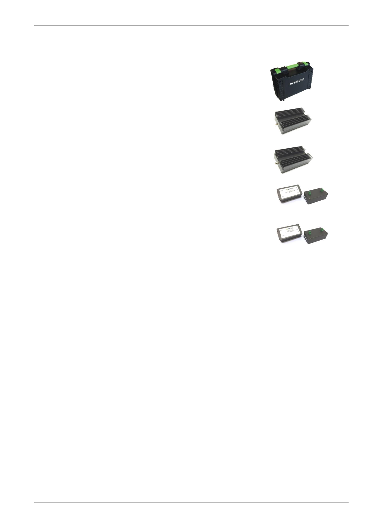
3.3.
Accessories
•User Software "AutoWave.control"
- Test, analyze and document under Windows
- License for testing of most automotive standards
- Report generator featuring export to text
Figure 3.1
•Frame Bus Terminator
Terminating resistor for the Frame Bus interface
Figure 3.2
•Printed-circuit board connector - DFMC
PHOENIX, DFMC Adapters, 1.5 mm2, with a push-in locking connection
Poenix Contact
Type: DFMC 1,5/16-ST-3,5-LR
Order No: 1790629
Figure 3.3
EM TEST PFM 200N Series
User’s Guide Ver. 1.21 9 / 45
3.4.
Optional Accessory CA LV124
Set for edge verification of the PFM 200N100.1 according to LV 124
•Case for LV 124 Calibration
- Rugged plastic case for storing the calibration loads for the CA LV 124
- 2 m BNC cable
- 2 laboratory cables 0.5 m (black, red)
- Calibration resistors for power and data lines
Figure 3.4
•CA LV124-P1R Calibration of Battery Lines
1,0 Ω± 1 %,
U max.: 12 V
P max.: 150 W
Figure 3.5
•CA LV124-P100R Calibration of Battery Lines
100.0 Ω± 1 %,
U max.: 100 V
P max.: 50 W
Figure 3.6
•CA LV124-D1R Calibration of Signal and Data Lines
1.0 Ω± 1 %
U max.: 2.0 V
P max.: 1 W, P Peak: 4W max.
Figure 3..7
•CA LV124-D1000R Calibration of Signal and Data Lines
1000 Ω± 1 %
U max.: 40.0 V
P max.: 1 W
Figure 3..8
3.5.
Optional Accessory CA LV124.1
Set for edge verification of the PFM 200N200 according to LV 124
•Case for LV 124.1 Calibration
- Rugged plastic case for storing the calibration loads for the CA LV 124
- 2 m BNC cable
- 2 laboratory cables 0.5 m (black, red)
- Calibration resistors for power and data lines
•CA LV124-P1R Calibration of Battery Lines
1,0 Ω± 1 %,
U max.: 12 V
P max.: 150 W
•CA LV124-P100R Calibration of Battery Lines
100.0 Ω± 1 %,
U max.: 100 V
P max.: 50 W
•CA LV124-D1R Calibration of Signal and Data Lines
1.0 Ω± 1 %
U max.: 2.0 V
P max.: 1 W, P Peak: 4W max.
•CA LV124-D1000R Calibration of Signal and Data Lines
1000 Ω± 1 %
U max.: 40.0 V
P max.: 1 W

EM TEST PFM 200N Series
User’s Guide Ver. 1.21 10 / 45
3.6.
Optional Accessory CA LV148
Set for edge verification of the PFM 200N100.1 according to LV 148
•Case for LV 148 Calibration
- Rugged plastic case for storing the calibration loads for the CA LV 124
- 2 m BNC cable
- 2 laboratory cables 0.5 m (black, red)
- Calibration resistors for power and data lines
•CA LV148-P10R Calibration of Battery Lines
10,0 Ω± 1 %,
U max.: 48 V
P max.: 30 W
•CA LV148-P1000R Calibration of Battery Lines
1000.0 Ω± 1 %,
U max.: 48 V
P max.: 30 W
3.7.
Optional Accessory CA LV148.1
Set for edge verification of the PFM 200N200 according to LV 148
•Case for LV 148 Calibration
- Rugged plastic case for storing the calibration loads for the CA LV 124
- 2 m BNC cable
- 2 laboratory cables 0.5 m (black, red)
- Calibration resistors for power and data lines
•CA LV124-P10R Calibration of Battery Lines
10,0 Ω± 1 %,
U max.: 48 V
P max.: 30 W
•CA LV124-P1000R Calibration of Battery Lines
1000.0 Ω± 1 %,
U max.: 48 V
P max.: 30 W
EM TEST PFM 200N Series
User’s Guide Ver. 1.21 11 / 45
3.8.
Installation
3.8.1.
Unpacking
Before shipment, the device is carefully tested and packed on a one-way pallet. Every box is marked with a
warning notice and packing list.
Before installation, check the contents the delivery contents for transport damage. Check that the packaging is in
good condition and ensure that the device does not exhibit any mechanical damage. If this is the case, please
immediately inform EM Test or their authorized representative before putting the device into operation.
Note: This guide uses the PFM 200N100.1 for illustrative purpose. Cases where the PFM 200N200 differs are
listed separately.
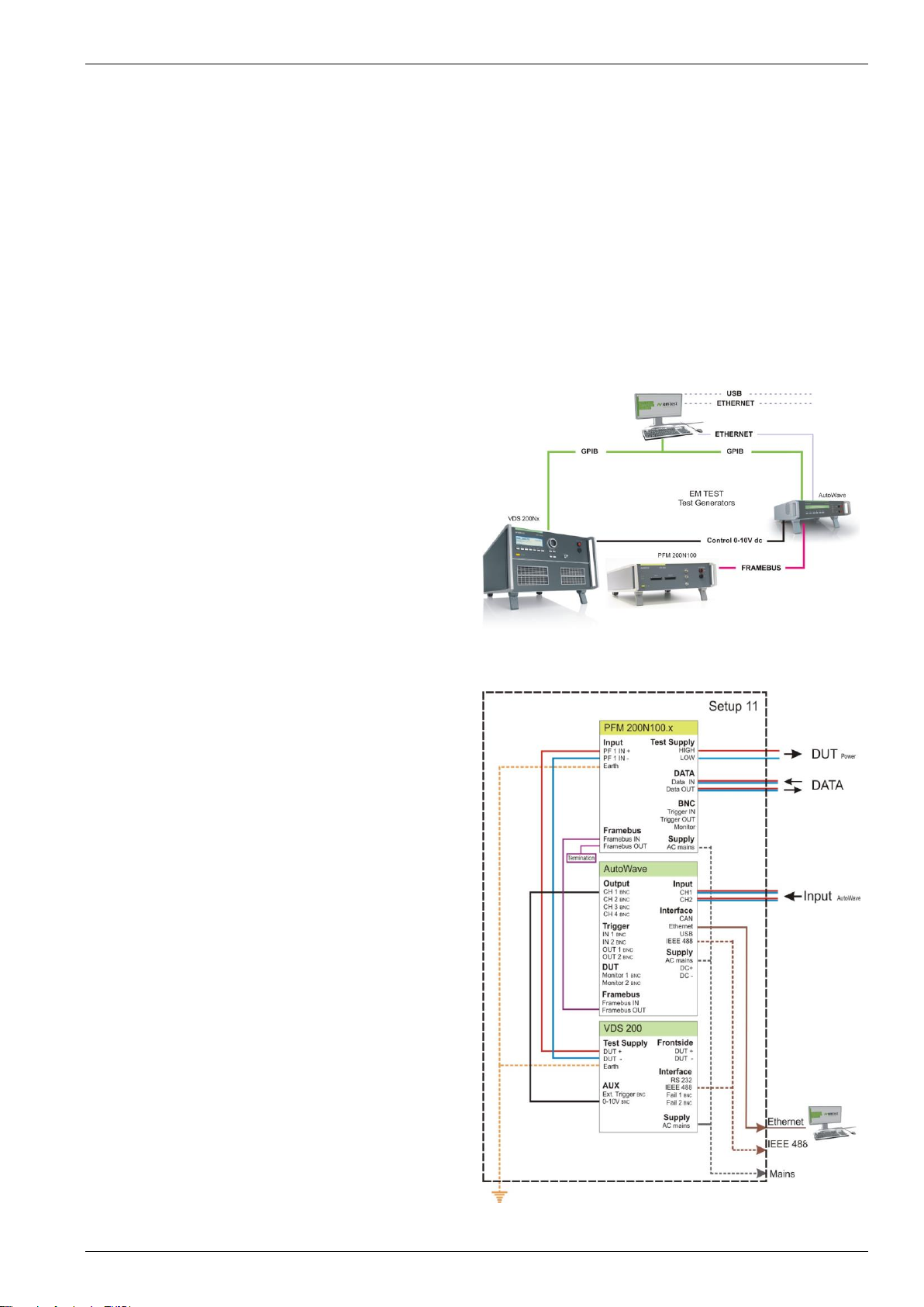
3.8.2.
Setup and Cabling the Test System
Control Cables
Figure 3.10 shows the typical usage of control cables
for the test system:
- AutoWave Controls the PFM
- PFM 200N100.1 Dropout simulator
- VDS 200Nx DC source for powering the DUT
AutoWave.control is required in order to operate the
PFM 200N100.1. This software contains all the test
routines for testing with the PFM 200N100.1
Figure 3.10: Control Cables
Cabling for the System
Figure 3.11 shows all connections necessary for the
PFM 200N100.1, AutoWave und VDS:
Cable List:
Computer –AutoWave
GPIB / IEEE488 or
Ethernet
AutoWave - VDS200N100
IEEE 488 IEEE488
CH 1 BNC 0-10V BNC
AutoWave - PFM 200N100.1
Framebus OUT Framebus IN 15 Pin D-Sub
VDS200Nx - PFM 200N100.1
DUT + PF1 IN + DUT power, 100A max.
DUT - PF1 IN - DUT power, 100A max.
PFM 200N100.1
Framebus OUT Framebus Termination
Earth Connection: VDS 200Nx and PFM 200N
Mains power: to all devices (1ph / 3ph)
Figure 3.11: Cabling for the System with a PFM 200N100.1
EM TEST PFM 200N Series
User’s Guide Ver. 1.21 12 / 45
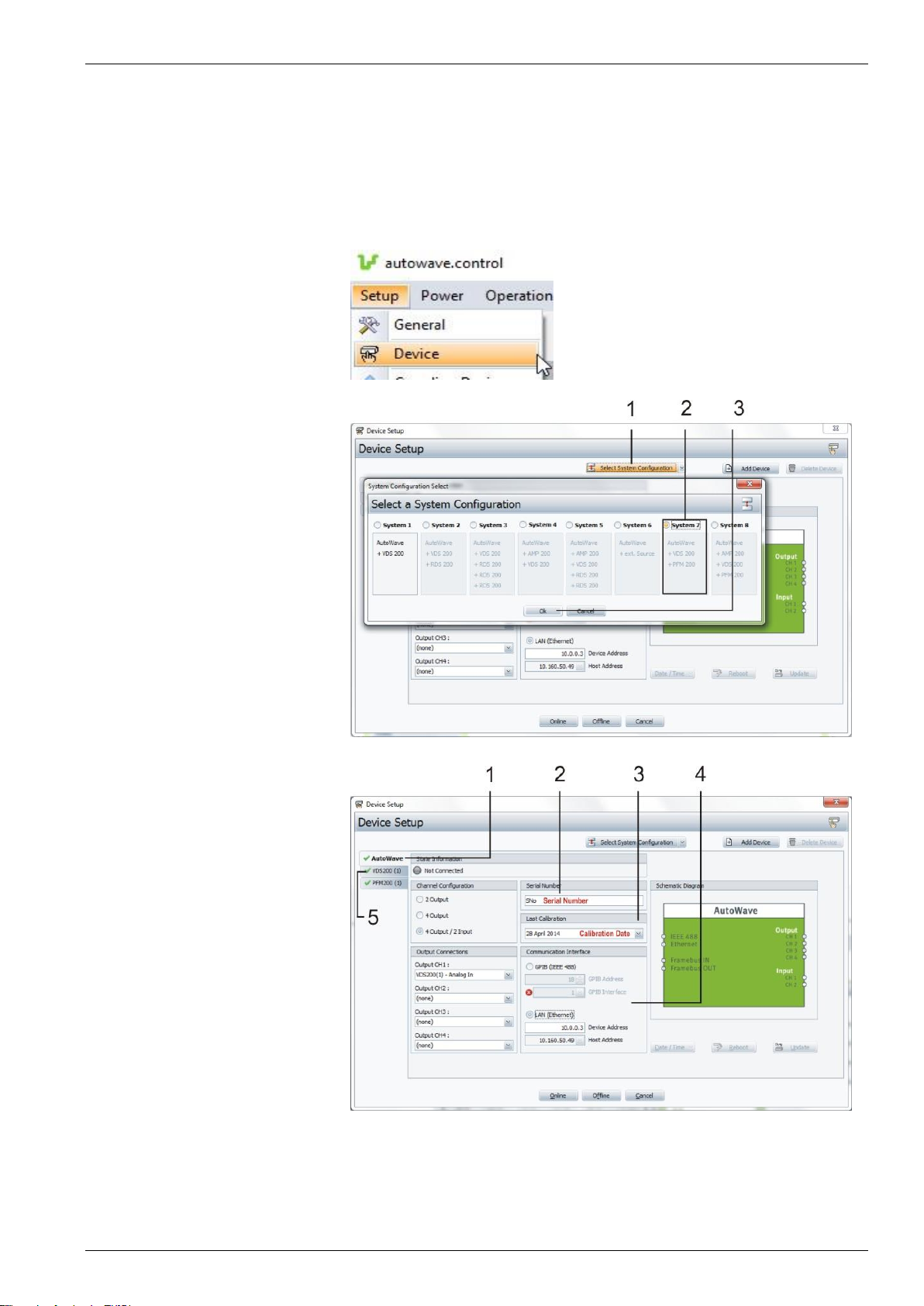
3.8.3.
Software Installation and Setup
To install the AutoWave.control, please consult the software user’s guide.
After installation use the Hardware Configuration tool to setup the AutoWave.
ASelect Setup / Device to open
the System Configuration.
Figure 3.12
B System Configuration
Here you can setup the software for
the correct system configuration.
1 Choose the selection
Select System Configuration
to open a typical configuration.
2 Select System 7 or System 8
or the one that most accurately
reflects your system.
3 Choose OK to close this
window.
Figure 3.13: System Configuration for a Typical PFM 200N100.1 Setup
C Device Setup
Here is where you enter the details
for the device.
1 First, select AutoWave
as the device to be edited.
2 Enter the Serial Number in the
list.
3 Enter the date from the
delivered certification.
4 Select the Interface to the
computer: GPIB or LAN.
5 Enter the details for the VDS.
Figure 3.14: Device Setup for AutoWave

EM TEST PFM 200N Series
User’s Guide Ver. 1.21 13 / 45
D PFM 200N Series Setup
Here is where you enter the details
for the PFM 200N in the Software.
1 Select the PFM 200N
to be edited.
2 Enter the calibration date for
the PFM200N.
3 Enter the PFM 200N Serial
number in the provided field.
4 Click Online to connect the
system and the computer.
Figure 3.15: Device Setup for PFM 200N100.1
If you should encounter any problems during connection, please consult the AutoWave.control software user’s
guide. Here you’ll find more information for the installation.
For further information about software, please consult:
- The user’s guide for the AutoWave.control software
- The example applications in this guide

EM TEST PFM 200N Series
User’s Guide Ver. 1.21 14 / 45
4.
Functions and Operation of the PFM 200N
4.1.
Front Panel Elements
Figure 4.1
1 Test enable button "TEST ON”
2 LED Power ON
3 LED Fail
4 Data line inputs L1 –L16
5 Data line outputs L1 –L16
6 Monitor BNC port
7 Trigger OUT BNC port
8 Trigger IN BNC port
9 DUT Test Supply LOW
10 DUT Test Supply HIGH
1 Test Enable Button “TEST ON”
Pressing the "TEST ON" button enables testing. The LED serves also as an optical indication when the switch
switches: the DUT power will be provided when the button is lit.
2 LED Power ON
This LED will light when the switch on the back of the device is switched on, indicating that the PFM is ready.
3 LED Fail
This LED will light when the PFM 200N detects an error. An error message will be displayed in a window in the
AutoWave.control software.
4 Data Line Inputs L1 –L16
16 pin PHOENIX, DFMC connector with 1.5 mm2, push-in locking connections.
Upper row: switched channel L1 to L16 (input)
Bottom row: return lines for the upper L1 to L16 switches
5 Data Line Outputs L1 –L16
16 pin PHOENIX, DFMC connector with 1.5 mm2, push-in locking connections.
Upper row: switched channel L1 to L16 (output)
Bottom row: return lines for the upper L1 to L16 switches
6 Monitor
Monitoring output for the DUT voltage at the test supply output using a differential measurement
Ratio 1:20, Amplitude 10 Vpp, ± 5 V
7 Trigger OUT, Oscilloscope Trigger
BNC trigger output (12 V pos. edge) for external measurement devices
8 Trigger IN
Trigger input to control the trigger the switch.
Signal (5 V neg. edge), delay ca. 100 µs
9 DUT Test Supply LOW
DUT output LOW with 4 mm (male) / 6 mm (female) connectors
10 DUT Test Supply HIGH
Switch DUT voltage output LOW 4 mm (male) / 6 mm (female) connectors

EM TEST PFM 200N Series
User’s Guide Ver. 1.21 15 / 45
4.2.
Back Panel Elements
Figure 4.2
1PF1 IN, DUT power input High
2PF1 IN, DUT power input Low
3 Reference Earth
4 Cooling Fan
5 Frame Bus Interface
6 Mains Power Input and Fuse
7 Power Switch ON/OFF
1 PF1 IN, DUT Power Input Low (VDS)
Input connector 4 mm and 6 mm (PFM 200N100.1) or BVT 10 (PFM 200N200) for DC power for the DUT (Low).
The generator must be connected to the reference earth of the test setup.
2 PF1 IN, DUT Power Input High (VDS)
Input connector 4 mm and 6 mm (PFM 200N100.1) or BVT 10 (PFM 200N200) for DC power for the DUT from
an external source (High)
Max. DC Voltage ±100V
- 6 mm connector 100 A
- 4 mm connector 32 A max.
3 Reference Earth
Earth connector with an M5 screw terminal and 4mm banana connector. The generator must be connected
to the reference earth in the test setup.
4 Cooling Fan
Cooling unit. At least 20cm around should be allowed for proper ventilation.
5 Frame Bus Interface
Interface for controlling the PFM 200N from an AutoWave. The output of the Frame Bus must be terminated with
the Framebus Terminator part no. 101732.
6 Mains Input and Fuse
The mains input has an integrated filter and fuse for the generator using (2x 2 AT) fuses. The generator power
supply is a universal power supply with a range of 100 V - 265 VAC, 50/60 Hz
7 Power Switch
Power ON/OFF Switch
EM TEST PFM 200N Series
User’s Guide Ver. 1.21 16 / 45
4.3.
Description of the Functions of the Device
4.3.1.
Front
Figure 4.3
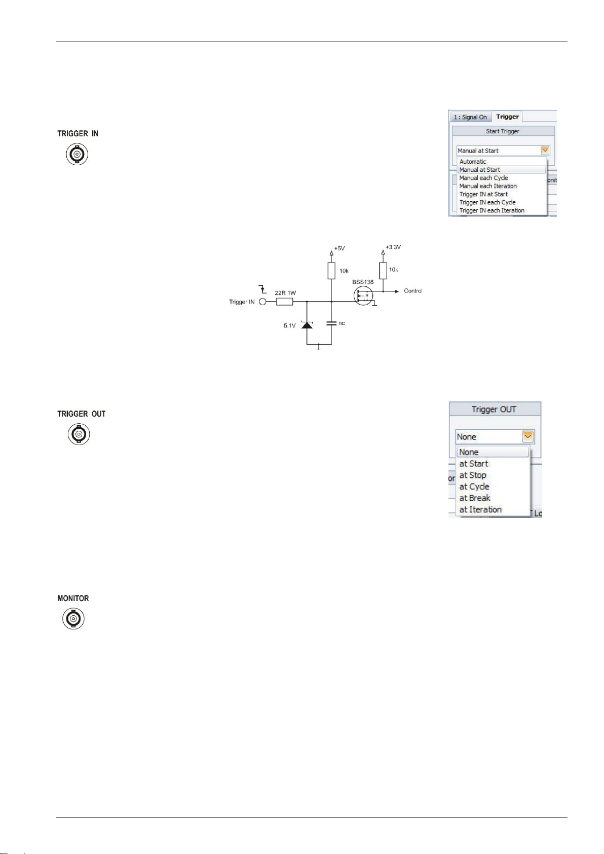
Trigger IN
Trigger to start an event
The trigger signal starts an interrupt. The
trigger can be set in the AutoWave software.
- Manual at Start
- Manual each Cycle
- Manual each Iteration
Figure 4.4 Trigger IN selection
Figure 4.5 Schematic - Trigger IN
Signal: 5 V, neg. edge
Delay: 100 µs
Jitter:
Figure 4.6
Trigger OUT
Output signal synchronized with the internal
switching control signal for an external
oscilloscope
Signal: 12 V, pos. edge
Current: 100mA
Delay: same as the switch control signal
Jitter:
Figure 4.7 Trigger OUT
selection
Figure 4.8
Monitor OUT
Allows monitoring of the output of the Test
Supply
Measurement: differential measurement
Ratio: 1:20
Amplitude: 10 Vpp, ± 5 V
Accuracy: ± 5%
Bandwidth: 10 MHz
EM TEST PFM 200N Series
User’s Guide Ver. 1.21 17 / 45
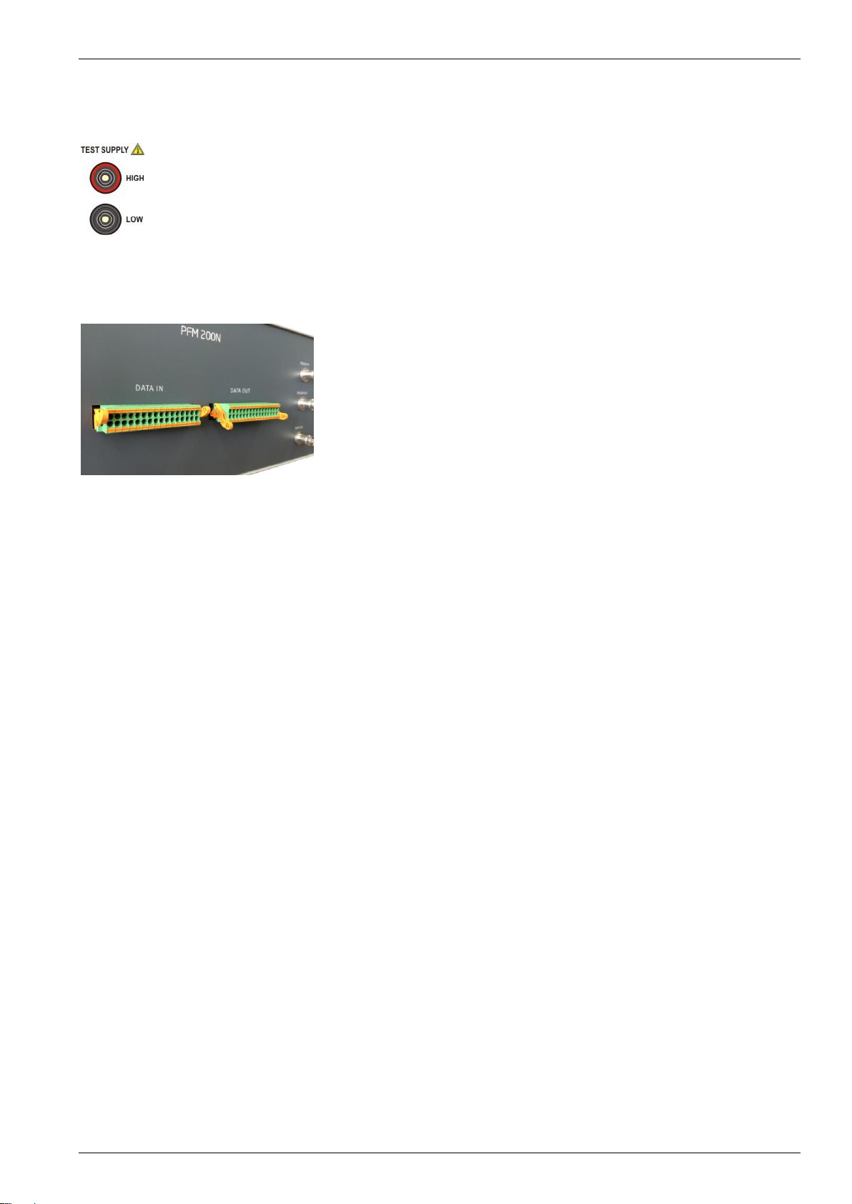
DUT Connections
Figure 4.9
DUT Power
Current capabilities PFM 200N100.1:
4 mm male: max. 32 A
6 mm female: max. 100 A
Current capabilities PFM 200N200:
KBT10: max. 200 A
(Mating connectors provided)
Figure 4.10
Data lines
The delivered connectors for the data lines are
equipped with spring-cage connections
Position of the spring-cage connector:
Open: upper position
Closed: lower position
Manufacturer: PHOENIX CONTACT
Model: DFMC series
Order No: 1790629
Poles: 16
Contacts: 32
Note: Depending on the signal, impedance and frequency, a small amount of crosstalk may be experienced when
using the data line switches.

EM TEST PFM 200N Series
User’s Guide Ver. 1.21 18 / 45
4.3.2.
Back
Figure 4.10
Input for DUT Power
Current capabilities PFM 200N100.1:
4 mm male: max. 32 A
6 mm female: max. 100 A
Current capabilities PFM 200N200:
KBT10: max. 200 A
(Mating connectors provided)
Figure 4.11
Frame Bus
Daisy Chain Bus with 15 pin Sub-D
male /female connector.
This interface is used to control various EM Test
devices.
Figure 4.12
Power and Fusing
The main on/off switch of the PFM 200N series acts as the mains input
and contains a mains filter and fusing.
Mains: 100V - 265V, 50/60 Hz
Fuse: 2 x 2 AT, 5 x 20mm

EM TEST PFM 200N Series
User’s Guide Ver. 1.21 19 / 45
5.
PFM 200N Dropout Simulator
The generator serves as the switching unit for dropout testing both power and signal lines required by
various requirements.
5.1.
Switch for DUT Battery Voltage
- Power Switch (S1P) for currents from 100 mA to 100 A (Inrush 400 A for 200 ms)
- Voltage ± 100 V DC
- Switching time < 1 µs (PFM 200N) < 200 ns (PFM 200N100.1 and PFM 200N200)
- Bidirectional switching capability
- Switch (S1N) on the ground line
- Integrated shorting-switch with < 100 mΩ during switch off (S2)
- Additional switchable impedances (R1…Rx), for predefined impedances of the on board power
system
5.2.
Switches for Data and Signal Lines
- Switch (S1 to S16) for currents from 100 µA to 2 A (Inrush 5 A for 200 ms)
- Bidirectional switching capability
- 16 switches for each sign or data lines
- Max. ± 40 VDC
The generator may only be used with AutoWave
5.3.
Block Diagram PFM 200N
Battery Lines
Switch S1 and S2 from the standards LV 124 and LV
148 have a slightly different name in the PFM 200N
Series and its associated software. Switch S2N in the
PFM 200N, used to interrupt the ground line, is not
found in the LV requirements, instead other standards.
Figure 5.1: Block Diagram PFM 200N100.1 with
descriptions corresponding to the AutoWave.control
software
LV Std.
PFM / Software
Power Switch High
S1
S1P
Shorting Switch
S2
S2
Power Switch Low
--
S1N
Data and Signal Lines
There are two connectors on the PFM 200N, each with
16 inputs and outputs. The upper row is switched and
the lower row is an unswitched return line.
EM TEST PFM 200N Series
User’s Guide Ver. 1.21 20 / 45
6.
Testing according to LV 124 and LV 148 using the autowave.control Software
Tests according to E-10, E-13 and E-14 uses an AutoWave for control. The user must use
AutoWave.control version 5.6.0 or newer.
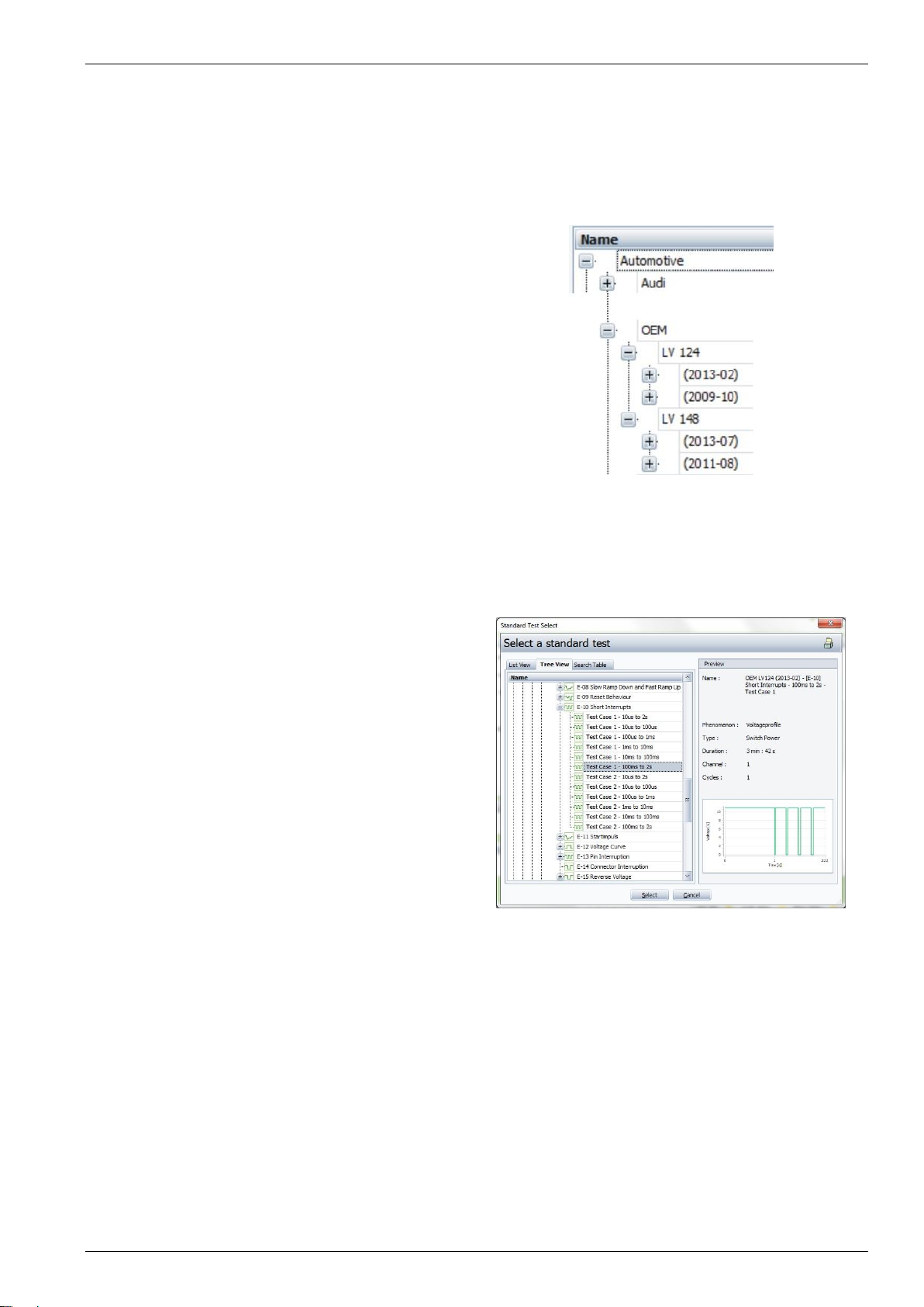
6.1.
Locating the Standard Tests for LV 124 and LV 148
LV 124 and LV 148 in the Standards Library
The standards LV 124 and LV 148 are found in
the Standards Library under Automotive –OEM.
Each standard contains various versions.
Figure 6.1: Standards list for LV 124 and LV 148
Selecting a Test
The user may choose the needed version and
test routine. Tests that do not user EM Test
equipment will not be found here. Each test step
is listed individually.
The example in Figure 6.2 the selection of a test:
LV 124(2013-02), E-10 Test Case 1 that includes
a dropout from 100ms to 2s.
Preview
In the right window of AutoWave.control a
preview of the selected test is displayed including
some general information about the selected test.
The picture in the preview window shows the test
run in a simplified way. The user has the
possibility to check the voltage profile of the test
run in a visual way.
Figure 6.2: Standard List for LV 124 Test Case 1 & 2
More Information about the Preview Window
Name: Standard name of the selected test
Phenomenon: Type of test (Voltage profile)
Duration: Duration of the entire test
Channel: Channel (AutoWave output)
Cycles: Number of Cycles
This manual suits for next models
2
Table of contents
Other EMTEST Test Equipment manuals

EMTEST
EMTEST esd NX30 User manual

EMTEST
EMTEST CWS 500A / 75 User manual

EMTEST
EMTEST AN 200 Series Instruction Manual

EMTEST
EMTEST VDS 200Q10 Series User manual

EMTEST
EMTEST PFM 200N100.1 User manual

EMTEST
EMTEST variac-NX 1-260-16 User manual

EMTEST
EMTEST CNI 508 N2 User manual

EMTEST
EMTEST dito User manual

EMTEST
EMTEST PFS 200N Series Instruction Manual

EMTEST
EMTEST CNI 503 Series Technical Document


