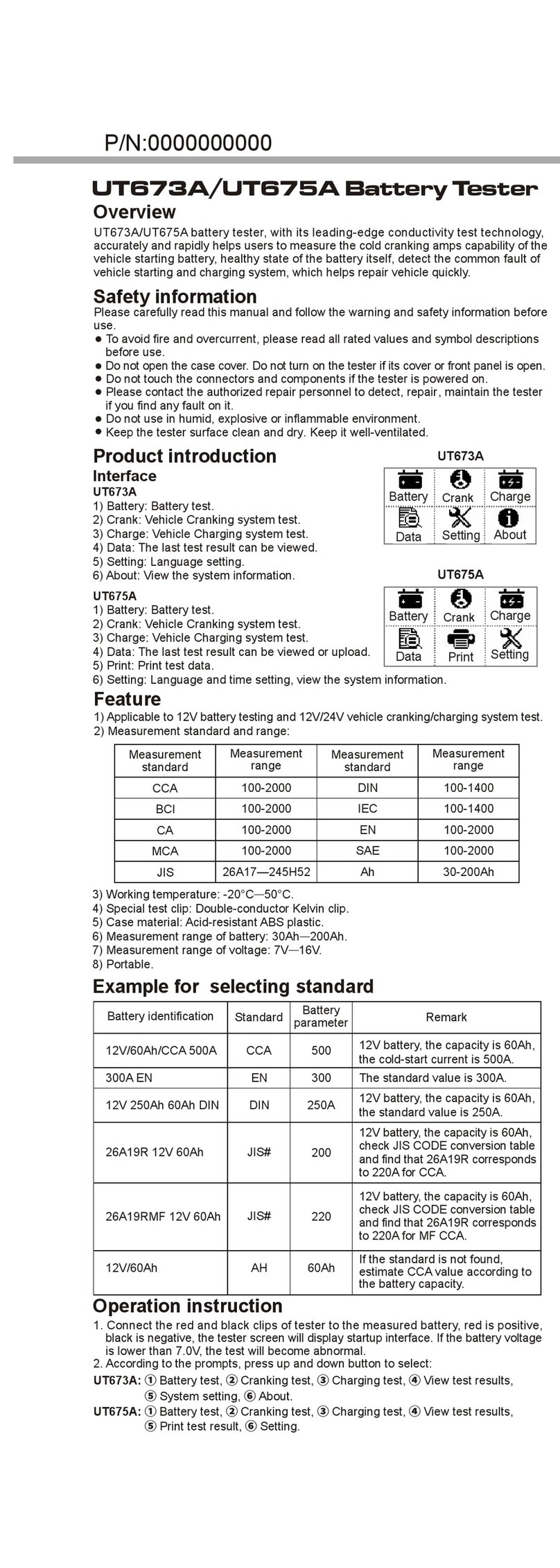
Unit UTD1000L Series User manual

User Manual
UTD1000L Series
DIGITAL STORAGE OSCILLOSCOPE

2011.09
UNI-T Technologies, Inc.


Preface
Dear users,
Thank you for purchasing UNI-T product. To operate the Oscilloscope correctly, please read
this Manual carefully and especially its “Safety Information” before use.
Afer reading it, you are suggested to keep the manual properly. Please keep it with the
Oscilloscope together or place it in an accessible location for future use.
UTD1000L User Manual 1

Copyright Information
UNI-T
: Uni-Trend Technology (China)Co., Limited. All copyrights reserved.
UNI-T
products, including obtained issued or pending patents, are protected by national or foreign patent
rights. Specifications and price change privileges reserved.
UNI-T
shall reserve all rights. Licensed software products are owned by UNI-T, its subsidiaries or providers
and protected by national copyright laws and international treaty provisions. Information in this publication
supersedes previously published materials.
UNI-T
is a registered trademark of Uni-Trend Technology (China)., Limited
Warranty period is 3 years since original purchaser purchases the product from UNI-T or authorized
distributor if product is sold or transferred to the third party within 3 years after original purchaser
purchases it. Probe, other fittings and fuses are excluded in this warranty.
UNI-T, at its option, either will repair products with defects independently without charge of parts and
labor or replace them by equivalent products if there is any defect during applicable warranty period.
Warranty parts, modules and replaced products of UNI-T may be new or with performance of new products
after maintenance. All replaced parts, modules and products become UNI-T properties.
“Users” mentioned below refer to rights persons or entities regulated under the rights of the warranty.
“Users” must report defects to UNI-T within appropriate warranty period and make proper arrangement in
order to get access to the service commiteed by the warranty. Users shall pack products with defects and
submit them to service center designated by UNI-T. In the meanwhile, they shall pay for freight fee in
advance and provide a copy of customer proof of original purchase. UNI-T shall pay for product return
expense to users if transporting product to location within state of UNI-T service center. Users shall pay for
all freight fees, tariffs, taxes and other expenses if returning products to any other locations.
The warranty is not applicable to any defect, trouble or damage caused by sudden accidents, normal
abrasion of machine parts, improper usage, maintenance or deficiency out of scope of product regulations.
UNI-T shall not be liable for providing the following services according to warranty regulations:
a) To maintain products which are damaged due to product installation, repair or maintenance by not UNI-T
service representatives.
b) To maintain damage caused by improper usage or connection of incompatible equipment;
c) To maintain damage or trouble caused by using power not provided by UNI-T;
d) To maintain products which have been altered or integrated with other products (if such alternation or
integration will increase product maintenance period or difficulty);
The warranty is signed by UNI-T with respect to the product in lieu of any other expressed or implied
warranties. UNI-T and its distributor refuse any implied warranty for marketability or suitability with special
purpose. UNI-T shall maintain or replace products with defect to users as the sole and exclusive for
warranty violation. UNI-T and distributors shall not be responsible for any indirect, special, incidental or
inevitable damage regardless of whether UNI-T and its distributors has advanced notice of the possibility of
such damages.
2 UTD1000L User Manual
Table of Contents
PREFACE 1
COPYRIGHT INFORMATION 2
TABLE OF CONTENTS 3
CHAPTER 1 SAFETY INFORMATION 6
1.1 SAFETY TERMS AND SYMBOLS 6
1.2 GENERAL SAFETY OVERVIEW 6
CHAPTER 2 UTD1000L SERIES OSCILLOSCOPE OVERVIEW 8
2.1 UTD1000L SERIES OSCILLOSCOPE INTRODUCTION 8
2.2 UTD1000L SERIES OSCILLOSCOPE ACCESSORIES 8
2.3 UTD1000L SERIES OSCILLOSCOPE KEY FEATURES 9
2.3.1 Scope 9
2.3.2 Multimeter 9
CHAPTER 3 CONNECTIONS TO THE OSCILLOSCOPE 10
3.1 GENERAL CHECK 10
3.1.1 Checking for any damage due to the transit 10
3.1.2 Checking the Accessories 10
3.1.3 Checking the Whole Oscilloscope 10
3.2 OSCILLOSCOPE CONNECTIONS 10
3.2.1 Connection Interfaces 10
3.2.2 Compensation Output Connection 11
3.3 FRONT PANEL AND KEYPAD 11
CHAPTER 4 USING BASIC OSCILLOSCOPE FUNCTIONS 15
4.1 ABOUT THE CHAPTER 15
4.2 POWERING ON THE OSCILLOSCOPE 15
4.3 DESCRIBING THE DISPLAY 15
4.4 RESETTING THE OSCILLOSCOPE 16
4.5 USING FUNCTIONAL MENUS 17
4.6 HIDING MENUS 17
4.7 MAKING CONNECTIONS FOR PROBE COMPENSATION 17
4.8 COMPENSATING THE PROBE 18
4.9 SETTING VERTICAL&HORIZONTAL SYSTEMS AND TRIGGER LEVEL MANUALLY 19
4.9.1 Vertical System 19
4.9.2 Horizontal System 19
4.9.3 Trigger Level 20
4.10 AUTOSET FOR WAVEFORM DISPLAY 20
4.11 FULL AUTOSET FOR INPUT SIGNAL 21
4.12 RUN/STOP DATA ACQUISITION 22
4.13 ADJUSTING SCREEN INTENSITY 22
4.14 SAVING BITMAP 23
4.15 USING ONLINE HELP 23
4.16 SETTING SINGLE TRIGGER 23
4.17 VIEWING OSCILLOSCOPE STATUS 24
4.18 CHECKING OSCILLOSCOPE SYSTEM INFORMATION 24
4.19 MAKING AUTO MEASUREMENTS 25
4.19.1 Measuring All Parameters 25
4.19.2 Measuring Customized Parameters 26
4.20 USING AVG MODE FOR SMOOTHING WAVEFORMS 27
4.21 USING PEAK DETECT MODE FOR PULSE PEAK DISPLAY 27
4.22 OBSERVING WAVEFORMS WITH USE OF PERSISTENCE 28
UTD1000L User Manual 3

4.23 SELECTING AC COUPLING 28
4.24 INVERTING THE WAVEFORM DISPLAY 29
4.25 AUTOSET FOR SIGNALS WITH DC OFFSET 30
CHAPTER 5 USING THE MULTIMETER 32
5.1 ABOUT THE CHAPTER 32
5.2 CONNECTIONS TO THE MULTIMETER 32
5.3 DISPLAY INDICATORS 32
5.4 MAKING MULTIMETER MEASUREMENTS 32
5.4.1 Measuring Resistance 32
5.4.2 Testing Diodes 33
5.4.3 Testing for Continuity 33
5.4.4 Measuring Capacitance 34
5.4.5 Measuring DC Voltage 34
5.4.6 Measuring AC Voltage 35
5.4.7 Measuring DC Current with UTD1000CL 35
5.4.8 Measuring AC Current with UTD1000CL 37
5.4.9 Measuring DC Current with UTD1000DL 38
5.4.10 Measuring AC Current with UTD1000DL 41
5.5 DATA HOLD 44
5.6 MAKING RELATIVE MEASUREMENT 44
5.7 SELECTING MANUAL/AUTO RANGING 45
CHAPTER 6 USING THE OSCILLOSCOPE IN DETAILS 47
6.1 ABOUT THE CHAPTER 47
6.2 SETTING VERTICAL SYSTEM 47
6.2.1 UTD1000L Channel Setup 47
6.3 SETTING HORIZONTAL SYSTEM 49
6.3.1 Changing Timebase 49
6.3.2 Moving Waveforms Horizontally 49
6.3.3 Zooming in/out Waveforms 50
6.3.4 Adjusting Trigger Hold-Off 50
6.4 SETTING TRIGGER SYSTEM 51
6.4.1 Common Setting 52
6.4.2 Edge Trigger 53
6.4.3 Pulse Width Trigger 54
6.4.4 Video Trigger 55
6.4.5 Slope Trigger 55
6.6 SETTING THE DISPLAY 58
6.7 SETTING AUTO MEASUREMENTS 59
6.8 RECORDING AND STORAGE 64
6.8.1 Recording 64
6.8.2 Storage 67
6.8.3 Recalling 69
6.9 MAKING CURSOR MEASUREMENTS 70
6.10 INTERFACE SETUP 71
6.11 UTILITY SETUP 72
6.12 EXECUTING MATHEMATIC FUNCTIONS 73
6.13 AUTOSET 76
CHAPTER 7 TROUBLESHOOTING 77
7.1 THE OSCILLOSCOPE CANNOT POWER ON: 77
7.2 THE OSCILLOSCOPE TURNS OFF A FEW SECONDS LATER AFTER POWERED ON: 77
7.3 MEASURING VOLTAGE AMPLITUDE IS 10 TIMES LARGER OR SMALLER THAN EXACT VALUE: 77
7.4 NO WAVEFORM DISPLAYS AFTER ACQUIRING SIGNALS: 77
7.5 THE WAVEFORM DOES NOT DISPLAY STEADILY: 77
7.6. THERE IS NO DISPLAY AFTER PRESSING DOWN RUN/STOP BUTTON: 77
7.7 THE DISPLAY SLOWS DOWN AFTER HAVING APPLIED AVG MODE FOR A WHILE: 77
7.8 THE WAVEFORM DISPLAY HAS A STAIR-STEPPING SHAPE: 77
4 UTD1000L User Manual

CHAPTER 8 SERVICE AND SUPPORT 78
8.1 UPDATING PROGRAM 78
8.1.1 Preparation before Update 78
8.1.2 Update Conditions 78
8.1.3 Program Update 78
CHAPTER 9 APPENDIXES 80
APPENDIX A: TECHNICAL SPECIFICATIONS 80
APPENDIX B MAINTENANCE 86
APPENDIX C CHINESE-ENGLISH REFERENCE TABLE FOR FRONT PANEL 87
UTD1000L User Manual 5

Chapter 1 Safety Information
1.1 Safety Terms and Symbols
Terms in the manual
Following terms may appear in this manual:
Warning: a Warning specifies conditions and actions that may pose hazards to the user.
Caution: a Caution identifies conditions and actions that may cause damage to the product or
other properties.
Terms on the product
Following terms may show on the product:
DANGER indicates any injury hazard immediately accessible as you read the marking.
WARNING indicates any injury hazard not immediately accessible as you read the marking.
CAUTION indicates any damage may happen to the product or other properties
Symbols on the product
Following symbols may show on the product:
High Voltage Refer to the manual Measuring Ground Terminal
1.2 General Safety Overview
The oscilloscope is strictly designed and manufactured as per safety/compliances: GB4793 safety
requirements for electronic measuring instruments, IEC61010-1, Overvoltage CATⅢ 600V and Pollution
Degree II.
Please review following safety precautions to avoid personal injury or any damage to this product or any
products connected to it. Operate the product as specified to prevent any potential hazards. Only the
qualified personnel can perform the servicing procedures.
Warning: To avoid electric shock or fire, use only the power adaptor specified for the Oscilloscope and
certified for the power grid by the country of use.
Warning: If the Oscilloscope terminals are input with voltages higher than 42 V (30 Vrms), to avoid
personal electric shock:
●Use only the insulated voltage probe, test leads and power adaptor supplied or specified by UNI-T for this
Oscilloscope Series.
●Please check multimeter test leads, oscilloscope probe and other accessories for any mechanical
damage. Please make the replacement if any damage is found.
●Remove all unused test leads, probe and other accessories.
● Insert the power adaptor first into AC socket before connecting it to the Oscilloscope.
6 UTD1000L User Manual

●Do not input voltages higher than 300V into scope terminals under CAT II measuring environment;
working voltage applied into multimeter terminals must not exceed 600V under CATIII measuring
environment.
●Do not apply working voltage higher than rated values on the Oscilloscope
●Use only the accessories supplied for the Oscilloscope, do not use them if any damages are found.
●Do not plug any metal object into the connectors
●Use the Oscilloscope as specified.
●Rated voltage value mentioned in “Warning” is the “working voltage” limit for the power adaptor. It
represents Vrms (50-60Hz) when applying AC sinewave.
Only qualified staff can perform the servicing.
Check all terminals ratings: To avoid fire or electric hazard, please observe all ratings and symbols on the
Oscilloscope. Read through the manual for details before making connections to the Oscilloscope
Do not operate with suspected failure: Please have it checked by qualified servicing staff if you doubt the
product does not work normally.
Do not operate in damp environment.
Do not operate in explosive environment
Keep the product surface clean and dry
UTD1000L User Manual 7

Chapter 2 UTD1000L Series Oscilloscope Overview
2.1 UTD1000L Series Oscilloscope Introduction
UTD1000L Handheld Digital Storage Oscilloscope (Hereinafter referred to as “The Oscilloscope”)
combines digital scope and multimeter functions just into one tool. The ease-of-use feature, excellent
technical indicators and multi-functions offered the Oscilloscope can get your work done much faster.
The series offers four models for your option:
Model
Bandwidth
Sample Rate
Channels
UTD1025CL
25MHz
200MS/s
Single Channel
UTD1050CL
50MHz
200MS/s
Single Channel
UTD1025DL
25MHz
250MS/s
Dual Channel
UTD1050DL
50MHz
250MS/s
Dual Channel
UTD1000L Series Oscilloscopes offer users a simple and clear front panel that helps to perform primary
operations, a design you often get used to and can save you a great amount of time to learn about the
Oscilloscope. In order to speed up calibrations and measurements, pressing AUTO button can make the
oscilloscope display proper waveforms and settings directly. Meanwhile the Oscilloscope offers SHIFT
button to combine with other buttons to further operate the menus much easier. Beside ease of use, this
series outstands itself with superb performance and powerful functions, such as remarkable trigger and
analysis ability, making it easy to capture and analyze the waveforms; high-definition Display and math
function, ensuring a very clear and fast view on waveforms and finding out the signal problem.
2.2 UTD1000L Series Oscilloscope Accessories
Unpack the carton and you will see following accessories should be included:
No.
Description
Standar
d
1
UNI-T Oscilloscope
●
2
Power Adaptor, 1 pc
●
3
UTD1000CL Standard Probe, 1pc; UTD1000DL Standard Probe, 2 pcs
●
4
Multimeter Test Leads, 2pcs (one red, one black)
●
5
UTD1000DL standard UT-M04 (4A current divider module), 1pc;
UT-M10 (mA current module), 1pc.
UTD1000CL standard UT-M07 (10A current divider module),1pc
●
6
Oscilloscope probe adjusting tool, 1pc
●
7
USB wire, 1pc
●
8
Operating Manual, 1pc
●
9
CD (for communication software between PC and the Oscilloscope),
1pc
●
10
carrying bag, 1pc
●
2.3 UTD1000L Series Oscilloscope Key Features
2.3.1 Scope
● Totally Auto Scale; Vertical Scale and Timebase automatically adjusted with the signal and without any
manual interference;
●Unique and powerful Auto Setup, quick and accurate to set up for signals with any DC component;
● Wider voltage measuring range; Coupled with 10×probe with attenuation up to 200V/div;
8 UTD1000L User Manual

● Isolated USB for much safer communication;
●Color, White& black display for your option, perfect for use outdoors with strong sunshine.
● Intelligent local or network software update
●Unique waveform record, storage and recall functions
●High-resolution and high-contrast color LCD
●8 hours of continuous battery operation for UTD1000CL and 6 hours for UTD1000DL
●UTD1000L:22 types of auto measurements
●Simple Printscreen function
●Multilingual help information
2.3.2 Multimeter
● 3999 display count
●Voltage, current, resistance, diode, capacitance, continuity measurements offered
● Measure current up to 6A max(UTD1000DL 4A max).
● Extremely low internal resistance designed for current measurement, ensuring better measuring
accuracy.
● Independent multimeter and scope functions in one tool
UTD1000L User Manual 9

Chapter 3 Connections to the Oscilloscope
3.1 General Check
It is recommended that you should proceed following inspections when you get a new UT1000L series
oscilloscope.
3.1.1 Checking for any damage due to the transit
Contact UNI-T dealership or local UNI-T office immediately if the packing carton or foamed plastic
cushion is seriously damaged.
3.1.2 Checking the Accessories
The accessories supplied for the Oscilloscope are listed in the section “UTD1000L Series Oscilloscope
Accessories” hereinbefore. Please refer to the section and check if any accessory is missing.
Please contact UNI-T dealership or local UNI-T office if there is any damage or missing item.
3.1.3 Checking the Whole Oscilloscope
If the Oscilloscope is found damaged externally or it does not work normally or pass any performance
test, contact our UNI-T dealership or local UNI-T office
If the product is damaged due to the transit, keep the package and inform the shipping agency and UNI-T
dealership, UNI-T will arrange the maintenance or replacement for you.
3.2 Oscilloscope Connections
3.2.1 Connection Interfaces
See Figure 3-1 for the Oscilloscope connection interfaces
5 6
Figure 3-1 Oscilloscope Connection Interfaces
10 UTD1000L User Manual

Description:
1. Input terminals for scope channels.
2. USB Connection port
3. The port to connect power adaptor for AC power supply and battery charge.
4. Output terminal for probe compensation
5. UTD1000CL multimeter input terminals.
6. UTD1000DL multimeter input terminals.
3.2.2 Compensation Output Connection
Connect to the output (1 kHz/3V) terminal as shown below for the Oscilloscope probe compensation.
Figure 3-2 Compensation Output Connection
3.3 Front Panel and Keypad
Learn about the Oscilloscope front panel and buttons shown in Figure 3-3:
Figure 3-3 UTD1000L Series Front Panel
UTD1000L User Manual 11

: To power on/off the Oscilloscope
F1~F4: To set up the submenus
: To toggle between Scope (DSO) and multimeter (DMM) modes.
: Press this button to access ACQUIRE (sample mode) menu if under DSO mode; press SHIFT first
and then this button to access intensity, with help of right and left arrow buttons, you can change
screen brightness. If under DMM mode, pressing this button can access voltage measurement
menu.
: Press this button to access DISPLAY (Display mode) menu if under DSO mode; or press SHIFT
first and then this button to access CONFIGURE (interface configuration) menu; pressing this
button under DMM mode to access current measurement menu.
: Press this button under DSO mode to access MEASURE(auto measurement) menu; or press
SHIFT first and then the button to access COURSOR(cursor measurement)menu; if under DMM
mode, press the button to access resistance measurement menu and measure resistance/
diode/continuity/capacitance.
: In DSO mode, press it to access CHANNEL menu for UTD1000CL; repeatedly press to toggle
between two channel menus for UTD1000DL.
: In DSO mode, press the button to access FFT menu for UTD1000CL; or press
the button and then F1 button to toggle between FFT and MATH menus for
UTD1000DL. Press SHIFT first and then the button to access STATUS display.
: In DSO mode, press to access RECORD (waveform record) menu; or press SHIFT first and then the
button to access STORAGE menu.
: Under DSO mode, press to set up SINGLE (single trigger) function; press first SHIFT and then the
button to access REF (waveform recall) menu.
: Under DSO mode, press to automatically set up the waveform; press SHIFT first and then the
button to switch on full autoset function. The Oscilloscope can automatically adjust the ranges to
obtain optimal waveform based on the input signal without any manual interference.
: Under DSO mode, press to start/stop data acquisition; if under DMM, press the button to lock
measuring readings on the screen.
: Under DSO mode, press to access TRIGGER menu; or press SHIFT first and then the button to
access UTILITY menu;
: Under DSO mode, press to access HORIZONTAL menu; or press SHIFT first and then the
button to open HELP information.
12 UTD1000L User Manual
: Combine with other buttons to select function options
Timebase: To change scan rate, ranging from 50s/div~10ns/div for 25MHz-bandwidth models and
50s/div~5ns/div for 50MHz-bandwidth models and stepping in 1-2-5. Press “s” to access relatively
slower scan rate or “ns” to speed up.
Vertical Scale: To change vertical scaling, ranging from 5mV/div~20V/div and stepping in 1-2-5.
Press “V” to zoom in current vertical scale or “mV” to zoom out.
: To toggle between vertical position and trigger level, if vertical position is choosen, vertical
reference cursor turns solid, then you can move waveforms vertically with Up and Down buttons.
Press SELECT again to make trigger level cursor solid, and also use Up and Down buttons to adjust
trigger point location
Under MEASURE menu, this button is used to confirm selected parameters, or it is
to toggle between Cursor 1 & 2 under cursor measurement.
: Arrow and OK buttons: OK button is used to hide/display current menu; under DMM
mode, it is used to confirm if current divider has been properly connected when making A
current measurement.
Shortcut Buttons Description:
SHIFT + OK: To save current interface into internal memory, which can be exported externally by PC which
has been loaded with the Oscilloscope software.
SHIFT + AUTO: to open full autoset function, in which the Oscilloscope can automatically adjust vertical
scale and horizontal timebase based on the input signal so that the optimal waveform can be obtained
without any manual operation
SHIFT + F1/F2/F3/F4: To open main trigger menu
UTD1000L User Manual 13

Chapter 4 Using Basic Oscilloscope Functions
4.1 About the Chapter
This chapter only briefs users on basic functions of the Oscilloscope, for example, how to use menus and
execute basic operations, not a step-by-step introduction on all functions.
4.2 Powering on the Oscilloscope
UTD1000L Series can be powered by: the battery and power adaptor. The power supply voltage from the
adaptor is DC9V/1.5A. To operate the Oscilloscope normally, please use the power adaptor specified for the
Oscilloscope.
Press Power button and SHIFT light illuminates for 3 seconds, then the Oscilloscope logo appears,
indicating the Oscilloscope has already turned on.
4.3 Describing the Display
Figure 4-1 Display Interface
Besides the waveform, there are still a lot of details about the waveform and oscilloscope control settings
on the screen:
1. Trigger source status:
CH1/CH2: indicates you can adjust the waveform of this channel
REF: indicates you can adjust the recalled waveform.
FFT: indicates you can execute FFT operation on the waveform.
2. Trigger coupling:
AC ac-coupled
DC dc-coupled
HF high-frequency reject
3. Trigger level readout
4. Trigger status:
ARMED The Oscilloscope is acquiring all pre-trigger data and ignores all trigger events;
READY The Oscilloscope has acquired all pretrigger data and is ready to trigger;
TRIG’ED The Oscilloscope has detected out one trigger and is acquiring posttrigger data;
STOP The Oscilloscope has stopped acquiring waveforms
AUTO The Oscilloscope is in auto mode and acquires waveforms without trigger;
SCAN The Oscilloscope continuously acquires and displays waveforms under scan mode.
5. The time readout that indicates how far the trigger point is from the central point;
14 UTD1000L User Manual

6. The power supply indicator:
●The Oscilloscope is powered by the battery;
The Oscilloscope is powered by DC power adaptor.
7. The marker for ground reference point for displayed waveforms;
8.1×: indicates probe attenuation factor for the channel is 1×;
9. The readout for main timebase setting;
10. “Connected to PC” icon;
11. Readout for the current vertical scale factor;
12. Waveform Invert Indicator that indicates that the waveform is reversely displayed;
13. Position readout from the channel reference marker to the horizontal line on the screen.
4.4 Resetting the Oscilloscope
To reset the Oscilloscope to the default, do the following:
1. Press SHIFT button, “shift” icon displays on the upper right corner of the screen;
2. Press UTILITY button and four options shows on the bottom display;
3. Press F2 button to select the default setup. Then the Oscilloscope is set to the default settings;
Note: Pressing up arrow button can also set the Oscilloscope to the default when powering on.
Figure 4-2 Default Setup
The Default setup is as follows:
Functions
Default Setup
Acquire Mode
Normal
SEC/DIV
1ms/div
VOLT/DIV
100mV/div
Trigger Coupling
DC
Channel Status
CH2 Off (1000DL series)
Trigger Mode
Auto
Display Format
Vector
Persist Time
Auto
Display Style
Classic
Manual Display
Manual
UTD1000L User Manual 15
4.5 Using Functional Menus
The procedures below show you how to select functions with use of oscilloscope menus;
1. Press any functional button on the keypad, then corresponding options will show on the bottom display,
you can select one of these options with use of F1 ~ F4. After that, press OK button to hide functional
menus;
2. For the buttons printed with multiple functions, if you want to choose one of these functions, please
press SHIFT button first, accompanied by shift icon on upper right corner of display, then press the
corresponding button to obtain the function you want.
4.6 Hiding Menus
Press down OK button to hide all button icons and menus. To display menus or button icons, press OK
again.
Note: To set up auto hiding time for menus, please find corresponding option in CONFIGURE menu.
Figure 4-3 Hiding Menus
4.7 Making Connections for Probe Compensation
Connect the signal as follows:
1. Connect the probe connector to the Oscilloscope input terminal and switch probe factor to 10× on the
probe.
2. You also need to set up probe factor on the Oscilloscope, this factor changes vertical scale and ensures
the accuracy for measurements. To set up the probe factor on the Osciloscope, press CHANNEL button,
then F3 to set probe factor to10×.
16 UTD1000L User Manual
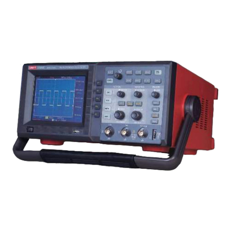
Figure 4-4 Adjusting Probe Factor
3. Conenct the probe to the output terminal for probe compensation on the Oscilloscope, press
AUTObutton, after several seconds, squarewave displays (1kHz, 3Vpp, Peak-to-Peak Value), See Figure 4-5.
Figure 4-5 Squarewave Signal from the Oscilloscope Itself
4.8 Compensating the Probe
You need to compensate the probe whenever connecting it to channels for the first time so as to match the
probe to the input channel. Uncompensated probe may cause deviation or error to the measurement. To
compensate the probe, do the following:
1. First of all, set probe factor on the Oscilloscope to 10×, turn the switch to 10× on the probe, then connect
the probe connector to the oscilloscope input channel and the probe tip to compensation output terminal;
2. Then execute AUTO
3. Observe the displayed waveform
Over Compensated Correctly Compensated Under Compensated
If the displayed waveform is under-or over-compensated as indicated above, use the adjusting tool with
non-metal handle to adjust the variable capacitor on the probe until correctly compensated waveform
shows.
Warning: To avoid any electric shock when measuring the high voltage with use of the probe, please ensure
the probe wire is perfectly insulated, and do not touch any metal part of the probe while connecting to the
high voltage source.
UTD1000L User Manual 17
This manual suits for next models
4
Table of contents
Other Unit Test Equipment manuals

Unit
Unit utd2000 User manual

Unit
Unit UT712 User manual

Unit
Unit UT2000 series User manual

Unit
Unit UPO2000E Series User manual

Unit
Unit UPO3000E Series Owner's manual

Unit
Unit UTD1000 Series User manual

Unit
Unit utd2000 User manual

Unit
Unit UT3200+ Series User manual

Unit
Unit UT5583 User manual

Unit
Unit UPO1000 Series User manual