Adam Pumps AF 3000 Setup guide

Adam Pumps S.p.A.
Soc. con Socio Unico
via della resistenza 46/48 - 41011 Campogalliano (MO) ITALIA
Tel +39 059 528128 - Fax +39 059 528437
UM002
7/2020 - rev. 6
AF 3000
ITALIANO
(lingua originale)
ENGLISH
(translation of original instructions)
IT
EN

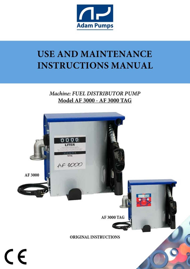
Machine: DIESEL FUEL DISPENSERS
Models: AF 3000
the use and maintenance manual must be carefully stored near the machine in an
environmentprotectedagainsthumidityandheat.Themanualmustaccompanythemachine
if sold. It is prohibited to damage, modify or remove any part of the manual.
EC DECLARATION OF CONFORMITY
(Annex II A DIR. 2006/42/EC)
THE MANUFACTURER
ADAM PUMPS S.p.A., with its registered ofce in Via della Resistenza, 46/48, 41011, Campogalliano (MO), ITALY; represented by
Davide Stassi, authorised to compile the relevant technical le at the undersigned premises,
DECLARES THAT THE MACHINE
Used as a diesel fuel pumping system to be integrated into a system for transferring fuel from a gravity tank.
COMPLIES WITH DIRECTIVES
Directive 2006/42/EC of the European Parliament and of the Council of 17 May 2006 on machinery, and amending Directive 95/16/
EC.
Directive 2014/30/EU of the European Parliament and of the Council of 26 February 2014 on the harmonisation of the laws of the
Member States relating to electromagnetic compatibility.
Directive 2014/35/EU of the European Parliament and of the Council of 26 February 2014 on the harmonisation of the laws of the
Member States relating to the making available on the market of electrical equipment designed for use within certain voltage limits.
Applicable only for AC powered products.
Place and date of the document
Campogalliano, January 14, 2020
The legal representative
USE AND MAINTENANCE MANUAL
FAC-SIMILE
ADAM PUMPS Spa
Via della Resistenza 48
41011 Campogalliano
Modena Italy
2016
JAN
Code : AR10014
ARMADILLO 100 230V
230 V - 50 Hz - 805 W - 4.5 A max - 1430 RPM - IP 55
Capacitor: 450 v-25 µF
30 min. Duty Cycle Weight Kg.:36
Batch of
Model
Description
Technical specications
Weight
TABLE OF CONTENTS
1 - GENERAL WARNINGS
2 - MACHINE SPECIFICATIONS
2.1 Intended use
2.2 Description of the machine
2.3 Technical specications
3 - OPERATING CONDITIONS
3.1 Environmental conditions
3.2 Power supply
3.3 Allowed uids / Forbidden uids
4 - TRANSPORT AND HANDLING
4.1 Transpor t
4.2 Unpacking
4.3 Storage
5 - INSTALLATION
5.1 Preliminary checks and positioning the
machine
5.2 Hydraulic pipe connection
5.3 Remarks on the suction and discharge lines
5.4 Electrical connection of the unit
6 - INTENDED USE
6.1 Preliminary checks and start-up
6.2 Daily use
6.3 Meter calibration
6.4 Noise level
6.5 Compatibility in an electromagnetic
environment
7 - TROUBLESHOOTING
8 - MAINTENANCE
9 - DEMOLITION AND DISPOSAL
10 - WARRANTY
11 - TECHNICAL SUPPORT
12 - ATTACHMENTS
12.1 Exploded views and spare parts list
12.2 Wiring diagrams
12.3 Overall dimensions and weights
EN

EN
The pump units described in this manual, once you have unpacked and installed them, are machines that
can ll a receiving tank with diesel fuel sucked from a gravity storage tank.
2 - MACHINE SPECIFICATIONS
2.1 - Intended use
2.2 - Description of the machine
The pump is made up of the following parts:
PUMP : volumetric self-priming rotary vane electric pump tted with a bypass valve.
MOTOR : the units are tted with one of the following motors, depending on the model:
Single-phase asynchronous motor, 2-pole, closed (protection class IP55 in compliance with Standard
EN60034-5-86), self-ventilating, directly anged to the pump body.
Brushed single-phase motor, with rectier circuit, directly anged to the pump body.
Brushed DC motor, directly anged to the pump body.
FILTER : stainless steel basket lter, can be inspected.
METER : device for detecting the litres of uid dispensed, tted with a reset knob and adjustment screw.
UNIT : assembly consisting of pump, connecting pipes and meter.
1 - GENERAL WARNINGS
IMPORTANT: It is essential to have understood the entire instruction manual before
performing any operation, so as to safeguard operator safety and to avoid potential product
damage.
Storing the manual: This manual must be kept intact and fully legible. The end user and the skilled
technicians authorised with installation and maintenance of the product in question must be able to consult
it at all times.
Reproduction rights: This manual is the property of ADAM PUMPS S.p.A., which is the sole owner
of all rights provided for by applicable law, including without limitation copyright rules. All rights under
these rules belong to ADAM PUMPS S.p.A.: reproduction, even partial, of this manual, its publication,
modication, transcription, public disclosure, distribution, marketing in any form, translation and/or
development, loan, or any other activity reserved by law to ADAM PUMPS S.p.A.
MODEL Power
supply(*)
Maximum
current
[Amp] (*)
Rated
power
[Watt](**)
Work cycle
[min]
Max flow
rate [l/
min]
Input/Output
[BSP-G](***)
Noise
[dBA] Hose Nozzle
AF3000 60
230V
50/60Hz
AC 230V
50/60Hz 2,9 550 (S2) 30 60 1" G-BSP 70 4m
Ø20
60 L
Automatica
AF3000 60
115V 60Hz
AC 115V
60Hz 8805 (S2) 30 60 1" G-BSP 70 4m
Ø20
60 L
Automatica
AF3000 70
230V
50/60Hz
AC 230V
50/60Hz 2,9 550 (S2) 30 70 1" G-BSP 70 4m
Ø20
90 L
Automatica
AF3000 80
230V
50/60Hz
AC 230V
50/60Hz 4,1 736 (S2) 30 80 1" G-BSP 80 4m
Ø25
120 L
Automatica
AF3000
100 230V
50/60Hz
AC 230V
50/60Hz 4,5 805 (S2) 30 100 1" G-BSP 80 4m
Ø25
120 L
Automatica

EN
3 - OPERATING CONDITIONS
3.1 Environmental conditions
3.2 - Power supply
(*) The values refer to operation of the pump in bypass (maximum performance)
(**) CAUTION! Operation in bypass is allowed only for brief periods (1-2 minutes at most)
(***) The noise levels are measured at a distance of 1 metre from the electric pump in normal operating
conditions. In order to maximise performance, pressure losses have to be minimised in the pump suction
line as follows:
- shorten the suction pipe as much as possible
- avoid, if possible, installing elbow ttings and/or throttling in the hydraulic circuit
- use a pipe with the same diameter or a diameter larger than the minimum specied in chapter 5
- INSTALLATION- always keep the lter inside the pump clean and regularly inspected
Temperature: min. -20°C / max. +60°C (*) Relative humidity: max. 90%
(*) Caution! The temperature limits shown refer to the components making up the pump and
should be respected to prevent any damages or malfunctions from occurring.
Depending on the model, the pump must be powered by the single-phase or three-phase AC line whose
values are given in the table in section 2.3 - Technical specications. Powering the pump with values
outside these limits can damage the electrical components or cause them to malfunction.
The maximum power supply variations allowed are:
Voltage: +/- 5% of the nominal value Frequency: +/- 2% of the nominal value
Allowed DIESEL FUEL with 2 to 5.5 cSt viscosity (at 38°C).
Minimum ash point (MF): 55 °C
Forbidden PETROL, FOOD LIQUIDS, WATER, FLAMMABLE LIQUIDS (MF <55°C)
SOLVENTS, LIQUIDS WITH > 20 CST VISCOSITY, CORROSIVE CHEMICALS
4 - TRANSPORT AND HANDLING
4.1 - Transport
The weight and dimensions of the machine allow it to be transported by hand and easily placed. The
machine does not require lifting equipment to move it.
the Manufacturer shall not be held liable for harm to people or animals or damage to
property resulting from use of lifting systems other than those specied.
Upon receipt, make sure the packaging is intact and in good condition. Any damage must be reported
immediately.
4.2 - Unpacking
Unpack the product as follows:
1. Place the box on the oor in the direction drawn on the packaging
2. Carefully open the box, remove the unit and place it on the oor or on a stable surface
3. After ensuring that the unit and any accessories are intact, remove the two plugs and install it as
described in the next chapter (5 - INSTALLATION).
4.3 - Storage
Prior to its use, the unit, still in its original packaging, should be stored in a dry and protected place in an
environment with the conditions described in Section 3.1 - Environmental conditions. Failure to follow these
instructions may affect proper operation of the product.

EN
5 - PRELIMINARY CHECKS
5.1 - Preliminary checks and positioning the pump
Make sure the unit has not been damaged while being transported or stored.Remove any remaining
packaging material from the product (e.g. protective caps) and carefully clean the suction and discharge
outlets.Install the unit in the desired position, in a place sheltered from rain and weather events.Position
and x the unit with suitably sized screws.For the centre distances of the holes, see section 12.3 - Overall
dimensions and weights.
5.2 - Hydraulic pipe connection
Before connecting the unit, make sure the tank, ttings and pipes used are clean and free from waste or
processing residues. Before connecting the discharge pipe to the unit, we recommend partially lling the
pump body with diesel fuel to lubricate and facilitate the priming procedure.
CAUTION! The motors are not explosion-proof. They must not be installed in areas with
ammable vapours or open ames.
CAUTION! Do not use couplings or connection ttings with conical threading, as these
could damage the pump coupling outlets if tightened too much.
We recommend using ADAM PUMPS suction and discharge pipes, which are designed
specically for the pump in use; alternatively, respect the dimensions and specications in
the table below.
"AF3000 60
AF3000 70"
"AF3000 80
AF3000 100"
Suction Discharge Suction Discharge
Unit inlet connection thread 1" G - BSP 1" G - BSP 1" G - BSP 1" G - BSP
Recommended minimum internal diameters Ø25 mm Ø19 mm Ø25 mm Ø25 mm
Recommended rated pressure 10 Bar 10 Bar 10 Bar 10 Bar
Pipe suitable for operation under negative pressure • •
5.3 - Remarks on the suction lines
SUCTION
LINE
The units in this manual mount self-priming pumps and can draw the liquid from a maximum height of 2 metres.
Caution, proper priming and the time required for this can be affected by an automatic nozzle on the discharge
line, which prevents normal air extraction from the pipe. It is therefore always advisable to prime the pump for
the first time without the automatic nozzle and with the discharge pipe emptied from the liquid. To facilitate the
subsequent start-up operations of the unit so that they are immediate, it is always recommended to install a foot
valve to prevent the suction pipe from emptying and to keep the pump wet. When the system is in operation, the
pump can work with negative pressure at the suction inlet up to 0.5 Bar, after which cavitation phenomena can start
with consequent reduction of the flow rate and increase in noise. To prevent this phenomenon from occurring it is
important to ensure low suction negative pressure, by using short pipes or pipes with a diameter larger than or the
same as those recommended, minimising bends and using large section suction filters and foot valves with the least
resistance possible.Moreover, it is very important to keep all suction filters clean to prevent the system resistance
from increasing when they are clogged.
DISCHARGE
LINE
The unit must be chosen based on the system’s specifications. Incorrect combinations of the length of the pipe,
of its diameter, of the flow rate of the diesel fuel and/or of the accessories installed on the line, can create a
counterpressure on the discharge line that is higher than the maximum set and so cause the pump bypass to open
(partially) with consequent reduction in the flow rate dispensed. To prevent this from happening and allow the
pump to work properly, the system resistance has to be reduced using pipes that are shorter and/or with a larger
diameter and line accessories with less resistance (e.g. an automatic nozzle for greater flow rates).

EN
5.4 - Electrical connection of the pump
Single-phase asynchronous
motors
To connect or replace the power cable, locate the pump, open the capacitor box cover and
follow the connection diagram to the side. Single-phase asynchronous motors are equipped
with phase capacitor and double-pole switch. The capacitor specifications are indicated for
each model on the pump’s rating plate.
Brushed motors
To connect or replace the power cable, locate the pump and remove the casings. Brushed
motors can be single-phase, 12 V DC or 24 V DC.
For DC versions, follow the polarity when connecting: RED = VCC (+, switch side), BLACK =
GND (-, motor side).For single-phase versions, connect following the colours: BROWN = L
(phase, switch side), BLACK = N (neutral, motor side), YELLOW-GREEN = earth cable to be
screwed to the back cover.
For proper installation and electrical maintenance of the system, please follow these instructions:
- make sure the power lines are not live when installing or carrying out maintenance operations on the system
- use cables with minimum section, rated voltages and type of installation suitable for the system’s specications
- always connect the unit’s earth terminal to the electricity grid’s earth line.
- always keep the capacitor box closed and sealed before electrically powering the pump
CAUTION! The units are provided without safety devices such as fuses, motor protectors,
systems against accidental restart after a power failure. Even the switch, if any, will only start/
stop the pump and can in no way replace a suitable circuit breaker. It is therefore the direct
responsibility of the installer to connect the unit to the main electrical panel in compliance with
the regulations in force in the country of use.
6 - INTENDED USE
6.1 - Preliminary checks and start-up
After ensuring there is diesel fuel in the suction tank, that all pipes and components on the hydraulic line
are in good condition and properly sealed, and the nozzle is closed, the unit can be started.
After inserting the nozzle into the lling hole, switch the unit on, gradually release the nozzle lever and
start transferring the diesel fuel. When you have nished lling, close the nozzle and switch the pump off.
If you are using an automatic nozzle, it will automatically close as soon as you have nished lling.
WARNINGS! Never leave the lling position to prevent accidental diesel fuel spillage. Do
not start the pump before having connected the suction and discharge pipes. Do not start or
stop the unit by inserting or unplugging any plugs. Do not touch any switches with wet hands.
Avoid direct contact of the diesel fuel with skin or eyes as it may cause harm. Use of goggles
and gloves is recommended.The motors are not tted with motor protectors and systems
against accidental restart. In the event of a power failure, remember to switch the unit o
and unplug it before restoring it.Work cycles that are continuous or in extreme conditions for
the unit can cause the motor temperature to rise and its subsequent shutdown by the circuit
breaker. Switch the unit o and wait for it to cool down before resuming work. The circuit
breaker automatically switches o when the motor has cooled suciently.
CAUTION! During the rst priming phase, the pump must be able to discharge the air,
initially present in the suction pipe and in the pump, from the discharge line. To facilitate this
procedure, make sure the nozzle or the discharge outlet is kept open. If an automatic nozzle
is installed on the discharge line, it is recommended to temporarily disassemble the nozzle to
facilitate pump suction during rst start-up.

EN
6.2 - Intended use
- If hoses are used, make sure the ends are properly connected to the tanks.
- Firmly hold the end of the discharge pipe to prevent accidental spillage.
- Before starting the pump, make sure the discharge valve or the nozzle is closed.
- When you are ready, switch the unit on. The pump can remain in bypass (internal circulation if the
discharge is closed) only for brief periods.
- With the pump on and in bypass, open the discharge valve or nozzle holding it rmly.
- When you have nished dispensing, close the valve or nozzle and switch the unit off.
CAUTION! Operation of the pump with discharge closed is allowed only for brief periods
(max 1-2 minutes). Make sure the unit is switched o after use.
If there is a power failure:
1. Close the discharge valve or nozzle
2. Put the end of the discharge pipe into its housing on the tank
3. Switch the unit OFF
When the power has returned, restart the unit as described at the beginning of the section.
6.3 - Smart Stop
The product has the ability to turn on or off the pump automatically when
the gun is inserted or removed dall’apposito accommodation. This function
is possible thanks to a special mechanism that is actuated when the gun
barrel touches the pallet behind.
Calibration is necessary when the litre counter is new, after dismounting, when a different uid is
measured or as consequence of signicant wear. Calibration of the litre counter can be changed easily
by following the calibration procedure listed below. For the calibration procedure it is necessary a test
container or a container of KNOWN volume. It is recommended that the container has a volume of at
least 19 litres (5 gallons).
Calibration Procedure
1. Follow Figures A-C (as for clearing of the lter) to access to the calibration screw;
2. Fill the container up to a known volume;
3. if the indicated quantity does not correspond to the known volume, the litre counter must be
calibrated. Make sure that the pump is closed and that the pressure is interrupted, hence remove the
sealing screws and rotate the calibration screw (Fig. A) in the anticlockwise direction to reduce the
indicated quantity, or in the clockwise direction to increase this quantity. A full rotation changes the
indicated quantity by about 0.4 of a litre. Reinstall the sealing screw;
4. repeat point 2 until the calibration is acceptable
1818
1616
1414
1212
16 18,516 18,5
g. A
6.4 -

6.5 - Noise level
Under normal operating conditions the noise emitted by all models does not exceed 85 dB at a distance of
1 metre from the electric pump.
6.6 - Compatibility in an electromagnetic environment
The machine is designed to operate correctly in an industrial electromagnetic environment,
and staying within the Emission and Immunity limits laid down in the following Harmonised Standards:
IEC EN 61000-6-2 Electromagnetic compatibility (EMC) - Generic standards - Immunity for industrial environments
IEC EN 61000-6-4 Electromagnetic compatibility (EMC) - Generic standards - Emission standard for industrial environments
EN
7 - TROUBLESHOOTING
PROBLEM POSSIBLE CAUSE CORRECTIVE ACTION
THE PUMP DOES
NOT START UP
Power failure Check the electrical connections and the safety devices
The circuit breaker has tripped Use the electric pump in the recommended operating conditions and
according to its intended use (chap. 2 - chap. 5)
Impeller blocked Make sure there are no obstructions in the pump body or along the
suction and discharge lines
Defective motor Contact the dealer (fault code M1)
LOW OR NO
FLOW R ATE
Low level of liquid in the tank Fill the tank
Filter dirty or clogged Clean or replace the filter
Foot valve dirty or clogged Clean or replace the foot valve
Pipe or dispensing nozzle damaged Replace the damaged components
Excessive negative pressure to the
suction line
Make sure there are no leaks or restrictions on the suction part
(recommended pipes chap. 5.2)
High pressure drops in the circuit Change the hydraulic discharge configuration
Bypass valve open or blocked Check the condition of the valve and clean or replace it if necessary
Vanes blocked Check and clean the vanes and their housings
Excessive wear of the vanes or impeller Replace the worn components
Leaks from the gaskets Make sure the gaskets are properly tightened and not worn
Incorrect power supply voltage Power the pump as specified on the rating plate
Defective motor Contact the dealer (fault code M2)
PUMP IS
VERY NOISY Cavitation
Reduce the negative suction pressure
Make sure there are no leaks or restrictions on the suction part
(recommended pipes chap. 5.2)
LITRE COUNTER
WRONG
The meter is not calibrated Calibrate the meter (chap. 6.3)
Meter obstructed Remove the obstruction or contact the dealer (fault code T1)
LIQUID LEAK
Air in the hydraulic circuit Make sure there are no suction leaks
Dispense to bleed the air from the circuit
Clamps loosened Make sure all clamps are properly tightened
Gaskets worn Replace the worn gaskets
Non-compatible liquids used Check compatibility of the fluid used (chap. 3.3)
Shaft seal ring dirty or damaged Contact the dealer (fault code A1)

EN
8 - MAINTENANCE
Maintenance includes inspections, checks and interventions which, to prevent interruptions and breakdowns,
systematically keep the machine lubrication status and the parts subject to wear under control. These
operations, although simple, must be carried out by Qualied Personnel.The machine is designed to
minimise routine maintenance. It is the operator’s responsibility to assess the status and its suitability for use.
We recommend stopping the operations and performing maintenance every time operation is not perfect.
This will always allow maximum efciency.
CAUTION! Make sure the unit is disconnected from the power supply and is not in
operation before carrying out any maintenance.
WARNING! Failure to comply with these requirements will release the manufacturer from
any liability resulting from the eects of the Warranty.
MAINTENANCE FREQUENCY MACHINE STATUS
SYMBOL
Make sure the pipes and couplings are properly
connected Every month Isolation for Maintenance purposes
Check/clean pipes and fittings Every 12 months Isolation for Maintenance purposes
Check/clean filter and fittings Every month Isolation for Maintenance purposes
Check/clean pump body Every month Isolation for Maintenance purposes
8.1 - Filter Cleaning
models AF3000 60-70L
A. Unscrew the screws that x the frontal plate and open the fuel dispenser
B. Identify the metallic locking plate under which it is the lter.
C. Completely unscrew the screw in correspondence with the FILTER inscription and loosen the other three.
Rotate clockwise the metallic locking plate and remove gasket and lter. Proceed with the cleaning.

EN
9 - DEMOLITION AND DISPOSAL
If the electric pump is to be scrapped, its parts are to be given to companies specialised in disposing of
and recycling industrial waste, as shown on the table below:
D. Relocate the metallic locking plate and tighten the screws. Position the frontal plate and close the fuel
dispenser.
models AF3000 80-100L
A. unscrew the screws that hold tight the front part of the metal sheet and open the distributor;
B. identify the lter to be cleaned in the lower part on the right of the pump and unscrew the plug;
C. extract the lter, clean it and screw back its plug;
D. replace in the original position the front metal sheet and screw back all seven screws.

PARTS TO BE
DISPOSED OF
DISPOSAL METHOD
PACKAGING The packaging consists of biodegradable cardboard which can be sent to companies for
normal pulp recycling.
METAL PARTS The metal parts, whether painted or stainless steel, are usually recycled by companies
specialised in the scrap metal industry.
ELECTRICAL AND
ELECTRONIC
COMPONENTS
These must be disposed of by companies specialised in disposing of electronic components, in
compliance with the requirements of Directive 2002/96/EC
PARTS OF A DIFFERENT
NATURE
Other parts making up the unit, such as pipes, rubber gaskets, plastic parts and wiring, are to
be given to companies specialised in disposing of industrial waste.
APPLICABLE REGULATIONS
FOR CUSTOMERS IN THE
EUROPEAN UNION
The European Directive 2002/96/EC states that the equipment bearing this symbol on the
product and/or on the packaging is not to be disposed of with unsorted municipal waste. The
symbol indicates that this product must not be disposed of with normal household waste. It
is the responsibility of the owner to dispose of these products and the other electrical and
electronic equipment through specific collection facilities appointed by the government or by
local authorities.
10 - WARRANTY
The warranty provided by the manufacturer Adam Pumps Spa covers the product for 2 years from the date of production.
Adam Pumps Spa (manufacturer) provides its customers with:
a warranty that covers problems resulting from production and conformity defects in the purchased products
the warranty period starts from the date indicated on the CE label which indicates the date of manufacture. A label indicating the date of
manufacture will be applied to those products which are not provided with a CE label. Therefore, the warranty period will start from that
date;
the warranty will become immediately null and void should the data of manufacture be illegible, for any reason, unless Adam
Pumps Spa is responsible for this;
the warranty covers repairs or replacement of the product, in the event it cannot be repaired
repair operations can be carried out only by Adam Pumps or by Adam Pumps’ authorised centres;
the warranty will not be valid in the event the product is tampered with by unauthorised persons, bodies, and/or companies;
any warranty request is subject to approval by Adam Pumps. The goods can be returned only if provided with an authorisation code.
Upon request, Adam Pumps will provide this code which will invoke the warranty for the product to be repaired or replaced;
unless otherwise agreed with Adam Pumps, the returned goods must be sent via transport pre-paid by who has invoked the
warranty to Adam Pumps Spa;
goods returned without authorisation and/or with transport not paid can be rejected;
The warranty will not be applied in the following cases
Failure to use or install the product according to Adam Pumps' instructions
The product has been used with unauthorised fluids.
The product has been modified or tampered with
The product is used in an area with power supply defects (voltage changes, current phase shift, etc.)
The product is used without the supplied suction filter (inside or outside the pump).
Immediately excluded from the warranty are: adhesive labels, plastic and metal casing, keyboards and masks, components
subject to wear such as blades, impellers, graphite brushes (where present in the motors), seals and gaskets in general.
11 - TECHNICAL SUPPORT
The Manufacturer is always available for any information required on installation, operation or maintenance
of the machine. The Customer should ask the questions clearly, with reference made to this Manual and to
the instructions listed.
EN

4C DESCRIPTION QTY
5MA998 FACEPLATE 1
6TF045 MECHANICAL NUMERATOR 1
TECH FLOW 3C-4C
EXPLODED VIEWS
3C DESCRIPTION Q.TY
1 TF014N BOTTOM COVER 1
2 TF013N TOP COVER 1
3 TF015G SIDE COVER WITH HOLE 2
4 60302000 PLASTIC CAP 1
5 MA999 FACEPLATE 1
6 TF044 MECHANICAL NUMERATOR 1
7 TF012X RESET KNOB 1
8 TF005 CONICAL GEAR 1
9 TF011 METER BODY 1
10 TF002 BOTTOM HALF-CHAMBER 1
11 TF003 TOP HALF-CHAMBER 1
12 TF001 SWINGING PLATE 1
13 OR001 O-RING Ø24 X 2 1
14 TF019 CALIBRATION SCREW 1/8" 1
3C DESCRIPTION Q.TY
15 TF018 CALIBRATION CAP 1/8" 1
16 11010100200 O-RING 108 NBR 1
17 11010050200 O-RING 2018 NBR 1
18 TF010 METER FLANGE 1
19 OR002 O-RING 4500 1
20 TF009 GEAR SUPPORT 1
21 TF008 PIN WITH LEVER 1
22 TF004 CYLINDRICAL GEAR 1
23 6051800000 ROLLER Ø2 1
24 TF006 DOUBLE GEAR WHEEL Ø36 1
25 TF007 GEAR WHEEL Ø45 1
26 11010040200 O-RING 2015 NBR 1
27 VT001 SCREW M6X20 4
28 80901439100 SCREW M4X10 2

PA1 70A 230V
CODE DESCRIPTION QTY
1 ME033 wound stator p80 1
2 ME032 machined shield p.80 1
3 ME034 motor shaft p.80 1
4 101001600000 bearing 6201 2rs 2
5 OR037 filter seal 1
6 OR038 motor shaft seal 1
7 OR039 o-ring nbr70 57x2 body pump 1
8 PA018 swivel locking plate 1
9 PA019 inox filter 16x49 1
10 PA020 capacitor 14μf 1
11 PA024 capacitor lock 1
12 PA025 fan fb63 d11 black wo/ring 1
13 PA026 ring d11 for fan fb63 black 1
14 CP009X pump body pa 70l x-treme 1
15 PA021 pin 3x3x12 uni 6604-a 1
16 61000003 rotor ø45 1
17 71000522 small vane 5
18 71000520 by-pass valve 1
CODE DESCRIPTION QTY
19 PA037 black reinforced bypass cap 1
20 16001005 by-pass spring 1
21 140250500000 mec 63 fan cover 1
22 11010040200 o-ring 2015 nbr 1
23 VT042 compensation ring 1
24 61004600000 tie rod m5 x 125 4
25 PA023 capacitor box 1
26 VT046 screw te m5x12 flanged 5
27 EL013 blue switch 22x30 1
28 140250300000 cable lock 1
29 VT004 screw tc ø3,5x16 2
30 17001011 cable gland rubber 1
31 17001012 cable gland ring nut 1
32 190200000000 shuko cable 230v 1
33 VT048 screw tc 3,5x12 5
34 VT049 screw tc 4x25 4
35 VT050 security washer 1
36 190110000000 faston cover 2
25
11
34
10
29 28
32
31
24
21
13
12
27 30
2
3
15
1
4
1920
23
6
14161778 2226
5
9
18
33
36
35
Num. articolo Num. parte Descrizione
Quantità
1
ME033
WOUND STATOR P80
1
2
ME032
MACHINED SHIELD P.80
1
3
ME034
MOTOR SHAFT P.80
1
4 101001600000
BEARING 6201 2RS
2
5
OR037
FILTER SEAL
1
6
OR038
MOTOR SHAFT SEAL AS 11x22x7 SNBR
INOX SPRING
1
7
OR039
O-RING NBR70 57x2 BODY PUMP
1
8
PA018
SWIVEL LOCKING PLATE
1
9
PA019
INOX FILTER 16X49
1
10
PA020
CAPACITOR 14µF 450V Ø35x71
1
11
PA024
CAPACITOR LOCK
1
12
PA025
FAN FB63 D11 BLACK WO/RING
1
13
PA026
RING D11 FOR FAN FB63 BLACK
1
14
CP009X
PUMP BODY PA 70L X-TREME
1
15
PA021
PIN 3x3x12 UNI 6604-A
1
16
61000003L
ROTOR Ø45
1
17 71000522
SMALL VANE
5
18 71000520
BY-PASS VALVE
1
19
PA037
BLACK REINFORCED BYPASS CAP
1
20 16001005
BY-PASS SPRING
1
21 140250500000
MEC 63 FAN COVER
1
22 11010040200
O-Ring 2015 NBR
1
23
VT042
COMPENSATION RING - DE29.4 DI22.2
1
24 61004600000
TIE ROD M5 x 125
4
25
PA023
CAPACITOR BOX
1
26
VT046
SCREW TE M5X12 FLANGED UNI5541
5
27
EL013
BLUE SWITCH 22X30
1
28 140250300000
CABLE LOCK
1
29
VT004
SCREW TC Ø3,5x16 AUTOFORMING UNI
6954 2
30 17001011
CABLE GLAND RUBBER
1
31 17001012
CABLE GLAND RING NUT
1
32 190200000000
SHUKO CABLE 230V
1
33
VT048
SCREW TC 3,5X12 UNI8112 AUTOFORMING
5
34
VT049
SCREW TC 4X25 UNI 9707 AUTOFORMING
4
35
VT050
SECURITY WASHER DIN 5406 15 MB 2
1
36 190110000000
6.3 FASTON COVER
2
4321
A
B
C
D
E
F
8765 1211109
G
H
A
B
C
D
E
F
G
H
1211109
8765
4321
Proprietà della ADAM PUMPS Spa - Senza autorizzazione scritta della stessa il presente disegno non potrà essere comunque utilizzato per la
costruzione dell' oggetto rappresentato, nè venire comunicato a terzi o riprodotto. La società proprietaria tutela i propri diritti a rigore di legge.
Formato
A2
Codice
Denominazione
PA1 70 230V
1:20
Scala
-
Materiale
Revisioni
Rev.
RM n°
Data
Firma
V.Perrotta
Disegnato
26/06/2018
1
Data
Tolleranze generali
UNI EN 22768-mK
SW-Massa
kg
Peso indicativo
Data
Approvato
1 di 1
Foglio
2 3 4 6 85 7 9
PA7A00
Proprietà
- Componente Adam Pumps -

CODE DESCRIPTION Q.TY
1 15501600000X MACHINED SHIELD MEC 63 1
2 6290150000L ENGINE SHAFT MEC 63 1
3 CP009X BODY PUMP PA 70L 1
4 PA018 SWIVEL LOCKING PLATE 1
5 PA019 INOX FILTER 16X49 1
6 PA020 CAPACITOR 14μF 450V 1
7 EL013 BLUE SWITCH 22X30 1
8 OR038 SHAFT SEAL Ø19 1
10 140250400000 FUN MEC 63 1
11 PA021 PIN 3x3x12 UNI 6604-A 1
12 OR039 O-RING NBR70 57x2 1
13 VT046 SCREW TE M5X12 5
14 OR037 FILTER SEAL 1
15 190110000000 COPRIFASTON 6.3 2
16 190200000000 SHUKO CABLE 230V 1
17 101001600000 BEARING 6201 2RS 2
CODE DESCRIPTION Q.TY
18 61004600000 TIE ROD M5 x 125 4
19 140250500000 FUN COVER MEC 63 1
20 61000003 ROTOR Ø45 1
21 71000522 SMALL VANE 5
22 71000520 BY-PASS VALVE 1
23 PA037 BLACK BYPASS CAP 1
24 16001005 BY-PASS SPRING 1
25 11010040200 O-Ring 2015 NBR 1
26 VT042 COMPENSATION RING 1
27 232204000000 WOUND STATOR MEC 63 1
28 PA023 CAPACITOR BOX 1
32 VT004 SCREW TC Ø3,5x16 2
33 140250300000 CABLE LOCK 1
34 VT037 SCREW TC M4x6 UNI 8112 5
35 PA024 CAPACITOR LOCK 1
36 VT049 SCREW TC 4X25 4
PA1 70A 115V

PA2 80 - 100
CODE. DESCRIPTION Q.TY
1 64100000000 Wrapped stator MEC 71 230V 1
2 PA023 capacitor holder + cap 1
4 140250300000 Cable lock 1
5 190061000000 Capacitor 25 μF 1
671000060 body pump 80 L 1"BSPG
71000079 body pump 100 L 1"BSPG
771000520 bypass valve 1
8 16001005 by pass spring 1
9 PA037 plate 1
10 41410000 inox filter 1
11 17001094 cap 1 " 1
12 18001008 O-Ring 3118 NBR 1
13 71000587 label "FILTER" 1
14 71000546 label “clear filter” 1
15 101001880000 Radial ball bearing 1
16 62901700000 crankshaft MEC71 1
17 101001700000 Radial ball bearing 1
18 15502600000X worked shield MEC 71 1
19 84505000000 Compensation ring Ø35 1
CODE. DESCRIPTION Q.TY
20 140260400000 fan MEC 71 with ring Ø14 1
21 140260500000 fan holder MEC 71 1
22 12001015020 Sealing ring 20x30x7 SNBR 1
23 90505050000 pin 6X6X20 UNI 6604-A 1
24 61000010 Rotor Ø72 1
25 18001022 O-Ring 85X3 NBR 1
26 71000063 pump holder 80-100 Lt. 1
27 82301410100 screw TC Cross M4 x 8 1
28 6100450000Z Tie M5X135 ZnB 4
29 71000569 big vane 7
30 13001007 screw TCCE M5x16 4
31 VT049 screw TC 4X25 UNI 9707 4
32 VT004 screw TC cross Ø3,5x16 2
33 VT048 screw TC cross 3.5x12 4
34 190200000000 cable + schuko plug 230V 1
35 EL013 switch 22X30 1
36 17001011 grommet gland 1
37 17001012 Cable gland nut 1

AF 3000
CODE DESCRPTION Q.TY
6 AF022 meter support 1
7 - mechanical meter 1
8 PA003 terminal cover FP71 1
9 PA004 plate with cable gland 1
10 71000550 Electrical box exit 1
11 17001011 cable gland rubber 1
12 17001012 cable gland ring nut 1
14 HT008L telephone 1" BSP-G 2
15 VT002 screw TCCE M5x8 1
16 MA060 label 1
18 -automatic nozzle 1
19 OR011 O-RING 37 x 3 NBR 2
20 OR017 Pipe rubber seal 1
21 OR022 terminal cover gasket 1
22 80901439100 screw TC M4x10 16
23 VT005 screw TE FR M8x16 6
24 VT014 Screw TC M4x16 4
25 81011810100 Screw TC M5x8 3
26 71000112 flanged nut M6 9
CODE DESCRPTION Q.TY
27 VT015 nut M4 UNI 5588 4
28 AF019 Nozzle holder A 1
29 71000532 meter pommel 1
30 163013500000 protection cap Ø31 2
32 80232320100 screw TE M6x14 1
33 83102310000 Washer 6x12x1.6 1
34 AF024 hose holde 1
35 VT031 plug d6 l50 1
36 SP005 gun padle spring 1
37 AF026 gun padle switch 1
38 190050150000 Microswitch 1
39 CA003 2X1 micro fms cable 1
40 VT034 screw TCCE M3x16 2
41 170 01106 Cylindric damper 20x20 4
42 AF028 lower sheet 1
43 HT016 panel 1
44 AF027 frontal closing sheet 1
45 - electric pump 1
22
40
28
45 29 20 7 32 6
33
14
45
19
23
41
43
21
5
24
82742
26
28
36
37
35
28
18
2534 44
16 38

S : switch ON-OFF
M: motor
T: thermal protection
C: capacitor
115V - 230V ac
AF 3000
OVERALL DIMENSIONS
WIRING DIAGRAM

Other manuals for AF 3000
1
Table of contents
Other Adam Pumps Water Pump manuals
Popular Water Pump manuals by other brands

Blue-White
Blue-White Flexiflo M3 Series operating manual
Goulds
Goulds Marlow 530 Series instruction manual

Pontec
Pontec MultiClear Set 15000 operating instructions
Equalizer
Equalizer HP350SD Operator's instruction manual

Power Fist
Power Fist 8879991 instructions
Graco
Graco HIGH-FLO 220-575 Instructions-parts list


