POS. DESCRIPTION REFERENCE QTY
230 Volts 115 Volts
1 STATOR MEC 63 232204000000 71009023 1
2 JUNCTION BOX SEAL 63/71-2 10501000000 1
3 CAPACITOR HOLDER Ø 10 140250100000 1
4 SCREW Ø 3,5 X 13 80801215000 10
5 CABLE FITTING 140250300000 1
6 SPACER WASHER Ø 4 80301400000 1
7 SCREW M4 X 8 82301410100 1
8 SWITCH 22 X 30 190050210000 1
9 SPADE CONNECTOR COVER 6,3 190110000000 6
10 JUNCTION BOX SEAL FKL 71 10502000000 1
11 CAPACITOR CLIPS 140250200000 1
12 BEARING 6201 2RS 101001600000 2
13 SHAFT ROTOR MEC 63 6290150000L 1
14 SPRING WASHER Ø 32 84500000000 1
15 FAN FLANGE MEC 63 15501600000X 1
16 HOUSING BOLT M5 X 125 61004600000 4
17 FAN MEC 63 WITH METAL RING Ø12 140250400000 1
18 FAN COVER MEC 63 140250500000 1
19 ELECTRIC BLACK CABLE 190200000000 190000190000 1
20 CAPACITOR 190060000000 190061000000 1
21 FLANGE 61715000000 61715000000 1
22 BY-PASS VALVE 71000520 71000520 1
23 PUMP HOUSING 60 LT 1”/ 1” 71000036 71000036 1
24 BY-PASS SPRING 16001005 16001005 1
25 BY-PASS CAP 71000521 71000521 1
26 O-RING 3118 18001008 18001008 1
27 METAL CAP 1” 17001094 17001094 1
28 SMALL PUMP FILTER 41140000 41140000 1
29 O-RING 132 11010200400 11010200400 1
30 METAL CAP 3/4” 17001006 17001006 1
31 “FILTER” STICKER 71000587 71000587 1
32 “CLEAN FILTER” STICKER 71000546 71000546 1
33 O-RING 2212 18001014 18001014 1
34 FLANGE PIN Ø4 X 14 91214140000 91214140000 1
35 ROTARY SEAL 10196 12010031000 12010031000 1
36 SHAFT KEY 3 X 3 X 15 17001097 17001097 1
37 PUMP ROTOR Ø45 61000003 61000003 1
38 VANE 71000522 71000522 5
39 SCREW M5 X 45 13001002 13001002 3
40 PLASTIC CAP Ø31 163013500000 163013500000 2
41 “DANGER” STICKER 71000653 71000653 1
42 “CE” STICKER 220000000000 220000000000 2
4. WARNING SIGNS
4.1 LABEL INDICATING THE DANGER
5. LIST OF PARTS
3.2 MECHANICAL RISKS
Parts subjected to wear:
• The vanes.
• The bearings.
• The rotor.
These parts should be replaced with original spare parts by
qualified personnel at authorized service centers.
3.3 MACHINE TECHNICAL DATA CHART
Motor constructive features:
Closed self - ventilated two poles motor with IP
55 protection, insulation class F.
Pump constructive features:
Pump body: G 25 CAST IRON
Motor rest: G 25 CAST IRON
Impeller: SINTERED IRON
Motor shaft: INOX STEEL
3.4 FLOW METER CALIBRATION
Calibration is required when the meter is new, after disassembly,
when metering a different fluid, or after significant wear.
A proving container or a container of KNOWN volume will be
needed for the calibration procedure. It is recommended that the
container volume be at least 19 litres (5 gallons).
Procedure for calibration
1. Fill container to a know volume.
2. If indicated amount on the flow meter does not match know vol-
ume, calibration is required. Insure pump power is off and sys-
BEWARE
IT IS FORBIDDEN TO CARRY OUT ANY JOB ON
ELECTRICAL EQUIPMENTS THAT ARE ON VOLTAGE
ANY DEPARTURE FROM INSTRUCTIONS, MUST BE AUTHORIZED
BY THE PERSON IN CHARGE
IN CASE OF UNUSUAL DANGER, ANOTHER PERSON MUST BE PRESENT
IN PLACE AS WELL AS WHO IS CARRYING OUT THE JOB
START WORKING IN ACCORDANCE WITH
THE PRECAUTIONARY MEASURES, ONLY!
In compliance with DPR.547 connected with the prevention of accidents
4 ADAM PUMPS • PA1 60 • PA2 80-100 L • LIGHTPUMP 60-80-100 L • DRUM TECH 60-80-100 L • HI-TECH 60-80-100 L
5.1 ELECTRIC PUMP PA1 60
MOTOR 115V
POS. DESCRIPTION REFERENCE QTY
230 Volts 115 Volts
1 STATOR MEC 71 64100000000 71009025 1
2 JUNCTION BOX SEAL 63/71-2 10501000000 1
3 CAPACITOR HOLDER Ø10 140250100000 1
4 SCREW Ø 3,5 X 13 80801215000 10
5 CABLE FITTING 140250300000 1
6 SPACER WASHER Ø4 80301400000 1
7 SCREW M4 X 8 82301410100 1
8 SWITCH 22 X 30 190050210000 1
9 SPADE CONNECTOR COVER 6,3 190110000000 6
10 JUNCTION BOX SEAL FKL 71 10502000000 1
11 BEARING 6202 2RS 101001700000 1
12 BEARING 6204 2RS 101001880000 1
13 SHAFT ROTOR MEC 71 62901700000 1
14 SPRING WASHER Ø32 84505000000 1
15 FAN FLANGE MEC 71 15502600000X 1
16 HOUSING BOLT M5 X 125 6100450000Z 4
17 FAN MEC 71WITH METAL RING Ø14 140260400000 1
18 FAN COVER MEC 71 140260500000 1
19 SHAFT KEY 6 X 6 X 20 90505050000 1
20 CAPACITOR 190061000000 1
21 ELECTRIC BLACK CABLE 190200000000 190000190000 1
22 BY-PASS VALVE 71000520 71000520 1
23 PUMP HOUSING 80 LT 1”/ 1” 71000060 71000060 1
24 BY-PASS SPRING 16001005 16001005 1
25 BY-PASS CAP 71000521 71000521 1
26 O-RING 3118 18001008 18001008 1
27 METAL CAP 1” 17001094 17001094 1
28 BIG PUMP FILTER 41410000 41410000 1
29 “FILTER” STICKER 71000587 71000587 1
30 “CLEAN FILTER” STICKER 71000546 71000546 1
31 O-RING 85 X 3 18001022 18001022 1
32 ROTARY SEAL 20307 12001015020 12001015020 1
33 PUMP ROTOR Ø72 61000010 61000010 1
34 VANE 71000569 71000569 7
35 PUMP COVER 71000063 71000063 1
36 SCREW M5 X 16 13001007 13001007 4
37 PLASTIC CAP Ø31 163013500000 163013500000 2
38 “DANGER” STICKER 71000653 71000653 1
39 “CE” STICKER 220000000000 220000000000 1
5.2 ELECTRIC PUMP PA2 80
MOTOR 115V
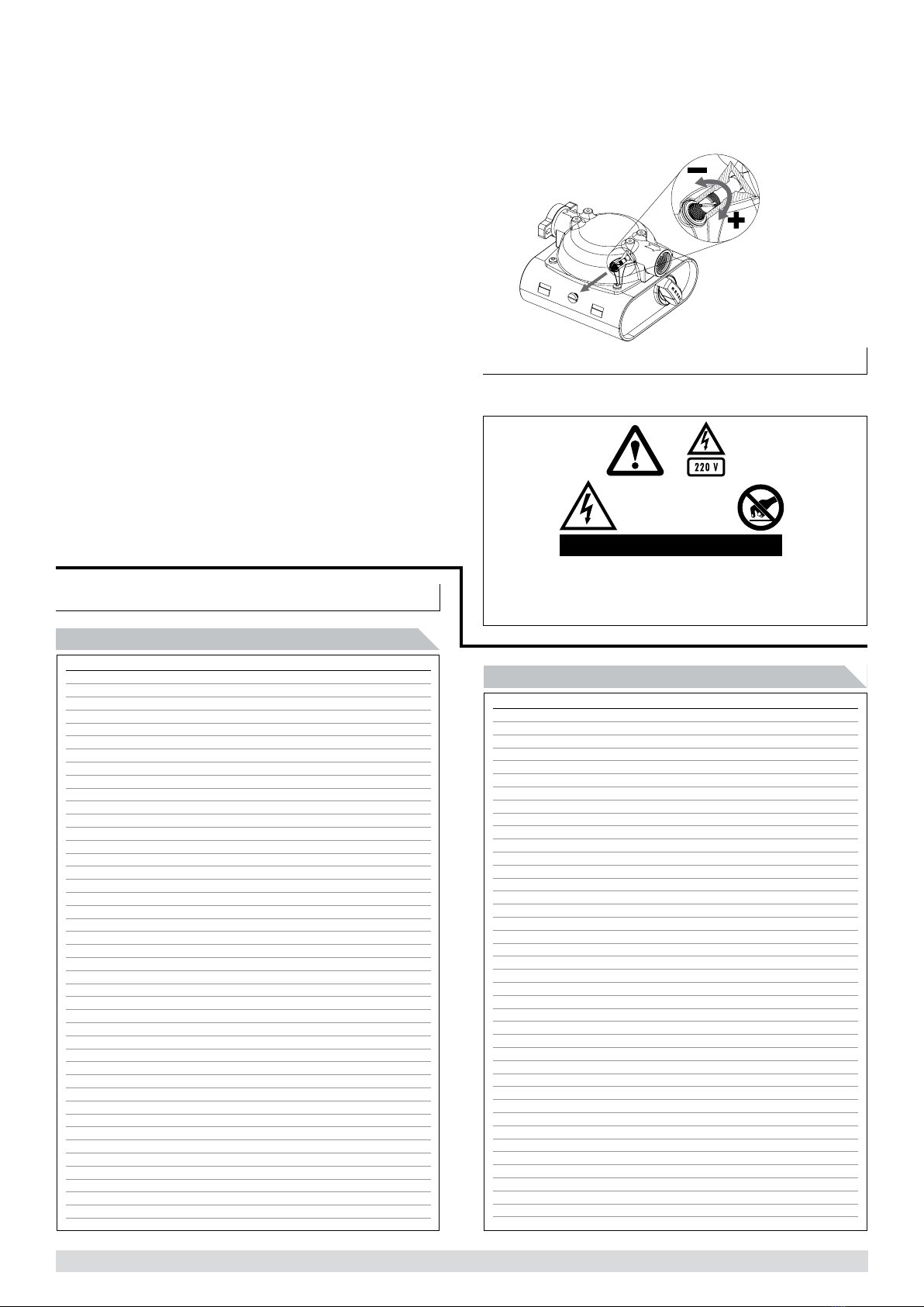
tem pressure relieved, then remove seal screw and turn calibra-
tion screw counter clockwise to reduce indicated amount or
clockwise to increase the amount. A full turn will change the indi-
cated amount by approximately 0.4L. Re-install seal screw.
3. Repeat step 2 until calibration is acceptable.
calibration procedure


