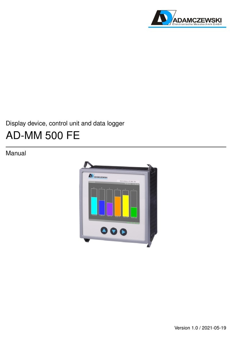
Adamczewski AD-VL 500 User manual

Display device, control unit and data logger
AD-VL 500
Manual
Version 1.0 / 2023-04-05

Contents
1 About this manual 4
1.1 Structure of the warnings ........................ 4
2 Safety 5
3 Product description 7
3.1 Block diagram .............................. 8
3.2 Display and operating elements ..................... 9
3.2.1 Status bars ............................ 9
4 Technical data 10
4.1 Supply .................................. 10
4.2 Housing ................................. 10
4.3 Environmental conditions ........................ 10
4.4 EMC ................................... 10
4.5 Electrical safety ............................. 10
4.6 Analogue inputs ............................. 11
4.6.1 Current inputs .......................... 11
4.6.2 Voltage inputs .......................... 11
4.6.3 Counter ............................. 11
4.7 Interfaces ................................. 11
4.7.1 RS485 interface ......................... 11
4.8 Configuration interface .......................... 11
4.8.1 Network interface ........................ 12
4.8.2 USB-Interface .......................... 12
4.9 Display .................................. 12
4.10 Operation ................................ 12
5 Assembly and commissioning 13
6 Operation and menu navigation 14
6.1 Key functions .............................. 14
6.2 Normal operation ............................ 14
6.3 Window navigation ............................ 15
7 Configuration 16
7.1 Analogue channel setup ......................... 16
7.2 Configuration menu ........................... 16
7.2.1 Device information ........................ 16
7.2.2 Analogue inputs ......................... 17
7.2.3 Windows ............................. 18
7.2.4 Display elements ......................... 18
7.2.5 Log channels ........................... 24
7.2.6 Log settings ........................... 25
7.2.7 Options .............................. 28
7.2.8 Network ............................. 28
2

7.2.9 RS485 .............................. 28
7.2.10 Delete files ............................ 29
7.2.11 Configuration .......................... 29
7.2.12 Backup to USB ......................... 29
8 Modbus 30
8.1 Basics .................................. 30
8.2 AD-VL 500 Data register ........................ 33
8.2.1 Local Modbus register ...................... 33
8.2.2 Modbus virtual registers ..................... 34
9 Wiring diagram 35
10 Network connection 37
10.1 Connection ................................ 37
10.2 Protocols ................................. 37
10.3 Data security ............................... 38
10.4 Navigation ................................ 38
10.5 Homepage ................................ 39
10.6 Configuration ............................... 40
10.7 Configuration pages ........................... 41
10.7.1 Device information ........................ 42
10.7.2 Analogue inputs ......................... 43
10.7.3 Configuration windows ...................... 45
10.7.4 Display elements ......................... 46
10.7.5 Log channels ........................... 47
10.7.6 Log settings ........................... 48
10.7.7 Options .............................. 49
10.7.8 Configuration files ........................ 50
10.7.9 Network ............................. 50
10.7.10 RS485 .............................. 51
10.8 Find devices in the network ....................... 52
10.8.1 Automated device call-up .................... 52
10.8.2 Manual unit call ......................... 52
11 Storage management and data formats of the files 53
11.1 Storage space management ....................... 53
11.2 Data structure .............................. 53
11.2.1 Memory requirements on the SD card .............. 54
11.3 Logfile .................................. 54
12 Maintenance and servicing 55
12.1 Firmwareupdate ............................. 55
12.1.1 Firmwareupdate with Configuration software AD-Studio . . . . 55
13 Help with faults 56
14 Appendix 57
14.1 Address of the manufacturer ....................... 57
14.2 Data evaluation ............................. 57
14.3 Device operating instructions ...................... 57
14.4 Device data sheet ............................ 57
3

1 About this manual
This manual is part of the product.
•Read the manual carefully before using the device.
•Keep the manual for the entire service life of the product and have it available
for reference.
•Pass the manual on to any subsequent owner or user of the product.
1.1 Structure of the warnings
Please consider the documentation. This symbol is intended to
warn you of possible hazards that could arise during assembly,
commissioning and use.
•Here, actions to avoid the danger are available.
•...
Structure of the hazard warnings
Danger to life or serious injury. Disconnect the system and the
unit from the power supply before starting work..
•Here, actions to avoid the danger are available.
•...
4

2 Safety
Intended use
The operating, maintenance and servicing conditions prescribed
in this manual must be strictly observed. Maintenance conditions
must be strictly adhered to.
The AD-VL 500 is intended for connection to an RS-485 interface to which other de-
vices are connected in bus mode.
The AD-VL 500 can be connected to a PC or laptop via the configuration interface.
The AD-VL 500 is intended for installation in front panels of control cabinets.
The AD-VL 500 has a connection for the supply voltage and can be supplied with AC
voltage up to 250V AC or 24V DC.
Any other use is not in accordance with the intended use!Unauthorised conversions
and modifications to the product lead to considerable safety risks and are prohibited
for safety reasons! Adamczewski elektronische Messtechnik GmbH is not liable for any
damage resulting from this or for damage or for damage resulting from improper use.
Malfunctions that may impair safety must be eliminated immediately! The installer
must make the manual available to the operator. The installer and the operator must
have read and understood the manual before starting their work.
Foreseeable misuse
In particular, this product must not be used in the following cases:
•In potentially explosive atmospheres. When operating in potentially explosive
atmospheres, sparking may cause deflagration, fire or explosion.
•Use on humans and animals.
Safe handling
This product complies with the state of the art and the recognised safety regulations.
Each unit is tested for function and safety before delivery.
Only operate this product when it is in perfect condition, taking into account the man-
ual, the usual regulations and guidelines as well as the applicable safety regulations
and accident prevention regulations.
Extreme environmental conditions affect the function of the product.
5

•Protect product from shocks
•Use product indoors only
•Protect product from moisture
Qualification of the staff
Installation, commissioning, operation, maintenance, decommissioning and disposal
may only be carried out by technically qualified personnel. Work on electrical parts
may only be carried out by trained in accordance with the applicable regulations and
directives.
Changes to the product
Unauthorised modifications to the product can lead to malfunctions and are prohibited
for safety reasons.
Use of spare parts and accessories
The use of unsuitable spare parts and accessories can damage the product. Please use
only original spare parts and accessories from the manufacturer.
Disclaimer
The manufacturer accepts no liability or warranty for damage or consequential dam-
age resulting from failure to comply with the technical regulations, instructions and
recommendations. The manufacturer is not liable for any costs or damage incurred
by the user or third parties as a result of the use of this appliance, especially in the
event of improper use, misuse or malfunctions of the connection, malfunctions of the
appliance or connected devices.
6

3 Product description
The AD-VL 500 is a display, control unit and data logger for front panel installation.
Measured values are displayed on a graphics-capable 3.5” TFT display.
Numerical data can be displayed in tabular form on an HTTP page.
The AD-VL 500 is primarily used for the acquisition and logging of up to eight ana-
logue measurement signals. It can still be connected via its RS-485 interface to one
or more units of the Adamczewski elektronische Messtechnik GmbH or also to units
of other manufacturers. Any data from these units can be displayed and/or logged to
an internal SD memory card. The stored data can be transferred to a USB stick for
further analysis at any time. The download of individual log files is also possible via
the web interface.
The AD-VL 500 communicates with the connected devices (slaves) via the Modbus
protocol and is always the Modbus master.
Features
•Display unit and data logger for front panel installation
•Buffered real time clock
•Display via graphics-capable TFT display
•RS-485 interface with Modbus RTU protocol
•USB connection for external data carriers
•PC interface or LAN interface for configuration or firmware update
•Creating your own displays with the Configuration software AD-Studio or web
interface
•8 analogue inputs for standard signals, current/voltage
•8 counters (software, configurable, derived from the analogue inputs)
•Integrated linearisation formulas or table for tank contents
•Up to 10 configurable windows
•Up to 40 configurable display elements in total
•Up to 12 configurable display elements per window
•Up to 32 configurable logical signal channels.
•Display element types: Numeric, Bar, LED, Time Chart, Drag Pointer
•Configurable display element properties: position, size, labelling, colors
•Display element functions: Color change definable by hysteresis or window func-
tion
•Three operating languages: German, English, French
7

Scope of supply
•AD-VL 500
•All required pluggable terminals
•This instruction manual
The optional USB programming adapter VarioPass is required for configuration with
the Configuration software AD-Studio .
Order code
AD-VL 500 RS-485 interface, configuration interface, USB port, Ethernet.
VarioPass (option) USB adapter for configuration and firmware update.
3.1 Block diagram
Figure 3.1: Block diagram of the AD-VL 500
The connections 1...8 mark the analogue input terminals that are physically present.
8

3.2 Display and operating elements
The AD-VL 500 has a color graphics-capable TFT display for showing the data and
three buttons for manual operation and configuration.
Figure 3.2: Display and operating elements of the AD-VL 500
Key ’Up’ Scroll up; increment digit
Key ’Down’ Scroll down; decrement digit
Key ’Set’ Confirm input
3.2.1 Status bars
In each display state, a header and footer bar with a grey background are shown in the
display with status information.
The header bar contains the following status information, from left to right:
•Window number: [1]...[10]
•Window description: freely definable description text
•Date stamp: current date
•Time stamp: current time
The footer contains the following status information, from right to left:
•LOG, for data logger function
•MB, for Modbus communication
•SD, for internal memory card
•USB, for external storage medium (USB stick)
•LAN, for network status
•DHCP, for IP address reference
•ADC, is only displayed in the event of a hardware error, colored red
•Function text Autoscroll, Read/Write UART/RS485
The display within the footer follows a color scheme:
inactive = black, active = green, error = red, info text/data traffic = yellow
9

4 Technical data
4.1 Supply
Designation Value
Supply voltage AC 50 ... 253 V
Supply voltage DC 20 ... 253 V
Max. Power consumption 3,0W / 5,0VA
4.2 Housing
Designation Value
Dimensions (WxHxD) 96x96x63 mm
Panel cut-out 92x92 mm
Protection class front cover IP 54
Protection class terminals IP 20
Connection technology removable screw terminals
Construction panel housing
Weight 350 g
4.3 Environmental conditions
Designation Value
Ambient temperature -10 ... 50 ◦C
Storage and transport -10 ... 70 ◦C (avoid condensation)
Degree of contamination 2
4.4 EMC
Designation Value
Product family standard EN 61326
Emitted interference EN 55011, CISPR11 Class B
4.5 Electrical safety
Designation Value
Product family standard EN 61010-1
10

4.6 Analogue inputs
4.6.1 Current inputs
Designation Value
Range 0...20 mA
Resolution 14 bit
Input resistance 50 Ohm
Sampling rate 1/s
Damping 0...999 s
4.6.2 Voltage inputs
Designation Value
Range 0...10 V
Resolution 14 bit
Input resistance 100 kOhm
Sampling rate 1/s
Damping 0...999 s
4.6.3 Counter
Designation Value
Input signal range 0...20 mA; 0...10...24V
Switching thresholds adjustable
Current input resistance 50 Ohm
Voltage input resistance 100 kOhm
Input frequency maximal 0,5 Hz
Pulse factor 0...10000
Pulse divider 1...100000
Range 0...999999
4.7 Interfaces
4.7.1 RS485 interface
Designation Value
Connector 3-pin socket 3.81mm pitch
Standard RS-485
Function Configuration, Modbus-Slave
Protocol Modbus-RTU
Max. Number of participants 32
Max. Bus length 100 m
Bus termination 120 Ohm (both ends at bus end)
4.8 Configuration interface
Designation Value
Connector jack socket 3mm
Standard UART, manufacturer specific
Function Configuration
11

4.8.1 Network interface
Designation Value
Connector RJ45 socket
Standard Ethernet, 10/100 Mbit/s
Addressing IP4
DHCP Factory activated
Protocol TCP/IP (HTTP, Modbus-TCP)
Standard address 192.168.50.230
Configuration port 80
Modbus-TCP-Port 502
Function Web server for configuration, file down-
load and numerical data view
4.8.2 USB-Interface
Designation Value
Connector socket type A for USB stick
Standard USB 1.0, 2.0
Formatting FAT12, FAT16, FAT32
Function Data transfer, configuration
4.9 Display
Designation Value
Typ 3,5” TFT
Resolution 320x240 Pixel
4.10 Operation
Designation Value
Type 3 short-travel keys
Network via web browser
12

5 Assembly and commissioning
Electrical connection
The terminals of the auxiliary voltage inputs are dangerous to
touch
.
•Disconnect the mains voltage and secure it against reconnection.
•Ensure that the connections are protected against accidental contact.
•Protect all connections against electrostatic discharge.
Commission the appliance
•Switch off the power supply.
•Check that there is no voltage.
•Mount the unit.
•Connect power supply and RS-485.
•Switch on power.
•Configure the unit. See chapter 7 for details.
•Check function.
13

6 Operation and menu navigation
6.1 Key functions
The menu is controlled by the three keys ’Up’, ’Down’ and ’Set’, see chapter 3.2. The
following abbreviations apply to the key functions:
up Key ’Up’ press briefly
UP Key ’Up’ press for longer than approx. 2s
down Key ’Down’ press briefly
DOWN Key ’Down’ press for longer than approx. 2s
set Key ’Set’ press briefly
SET Key ’Set’ press for longer than approx. 2s
NO key combinations are used in the entire menu navigation
(one-finger menu).
6.2 Normal operation
After power on the unit, it is in the display state with the display of the last window
shown. Press SET to enter the configuration menu. From the configuration menu,
press SET to return to normal operation.
In normal operation, the pre-configured windows can be scrolled through with up or
down or automatically.
In normal mode, among other things:
•Further display windows (windows 1...10) can be selected. The respective win-
dow number precedes the heading in square brackets.
•Settings are made on the AD-VL 500 .
Since the AD-VL 500 may access external Modbus slaves for data communication, a
higher-level error monitoring of the master-slave data traffic takes place at the RS485
connection. If an error is detected, the green status information MB immediately
changes to red. Possible errors are e.g.
•Timeout: The slave does not respond. Reasons can be an incorrect slave address,
the slave is not connected or does not respond for another reason.
•Slave Exception: Reasons can be e.g. an incorrect number of data words or an
incorrect or non-existent register.
14

This visual error message is not blocking. However, due to the time monitoring of the
Modbus slaves, there may be time delays in measurement recording in the event of
failures.
For diagnostic purposes, a short keystroke (set) can be used to display a log channel
table showing all 32 log channels with the currently set up Modbus slave address and
register ([channel] address/register).
Detected communication errors are marked with a Eafter this indication. This view is
automatically updated once per second. This table can only be activated in the event
of an error.
6.3 Window navigation
The AD-VL 500 can display up to 10 display windows. Up to twelve display elements
can be shown in one window. The current window number is shown in the display
header, before the heading, in square brackets. ([1] Headline).
Figure 6.1: Scroll window
The windows can be opened, as shown in Fig. 6.1 can be scrolled up and down
either manually with the ’Up’ and ’Down’ keys or automatically with a timer. A
longer keystroke (’UP’ or ’DOWN’) in any direction initiates automatic, time-controlled
switching to the next window. This state is shown in the footer with a yellow text
Autoscroll. Switching back to manual mode is done in the same way.
The time interval for the automatic scrolling function is set with
the parameter ⇒Options ⇒Autoscroll.
The default time is 5 seconds.
15

7 Configuration
The unit can be configured either directly on the unit, with the Configuration software
AD-Studio (for Windows operating systems) or via the web interface. The Adam-
czewski elektronische Messtechnik GmbH provides prefabricated
unit configurations, as XML files, are available.
The USB interface converter AD-VARIO-PASS is required for the PC/device connec-
tion with the Configuration software AD-Studio .
7.1 Analogue channel setup
Each of the eight analogue channels must be assigned the physical input signal (current
or voltage). See chapter 7.2.2 on page 17.
The signal is connected to the corresponding terminals.
See chapter 9 on page 35.
Each analogue input can be scaled in its own range to display and log scaled quantities.
The scaling does not yet contain a unit here. A scaling unit is set up directly on the
log channel (1...32).
Each analogue input signal can be linearised with a linearisation function or a global
linearisation table, by a function assignment characteristic. The linearisation table,
with 24 interpolation points, contains the physical input variable (mA/V) as the input
value and a numerical value as the output value.
See example in the web interface, chapter 10.10 on page 44.
The linearisation is done by interpolation between the interpolation points.
The linearisation of the different tank shapes, round tank (idealised) or spherical tank,
is done according to a calculation formula.
The signal normalisation is realised by a multiplication of linearisation and scaling.
7.2 Configuration menu
In the configuration menu, various configuration items can be selected on the
AD-VL 500 . If a configuration item requires a numerical index, the index selection
is activated and queried. The index setting is made by means of a rolling number,
which is set with the navigation keys. The numerical index is then shown in the menu
heading in square brackets.
Example: Configuration item [1].
7.2.1 Device information
Under device-information, various information on the status
of the AD-VL 500 is displayed. Available memory sizes of the mounted data carriers
are displayed here. A clear representation can also be found on the HTML status page
(see chapter 10.7.1 on page 42).
16

7.2.2 Analogue inputs
Only the parameters of the analogue functions are set in this area.
The Analogue Inputs menu branch contains the following submenu branches:
•Signal type I / U
•Characteristic linear, round tank, spherical tank, table
•Measuring range Lower range value, upper range value
•Scaling Scaling start, scaling end
•Filter XXX s
•Counter Counter reading, switching threshold, pulse factor, pulse divider
The following parameters are available for configuring the analogue inputs.
Parametername Default value Range Unit
Signal type I I / U
Characteristic linear linear, round tank,
spherical tank, table
Measuring range 0...20 lower range value,
upper range value
mA
Filter 0 0 ... 999
Counter, counter
value
0...999999
Counter,
Switching threshold
1,2 / 2,1 Messbereich mA
Counter, Pulse factor 0...10000 0
Counter, Pulse di-
vider
1...100000 1
The digital levels that control the counters are derived from the set-up counter switch-
ing thresholds. The corresponding values can be read on their own Modbus registers.
See chapter 8.2 on page 33.
For level detection, an analogue value must have safely reached the switching threshold
and assume a stable state for at least two seconds.
When using the voltage inputs as pulse inputs, voltage values up to 25 volts are per-
missible. However, they are only recorded analogue up to 10 volts.
An adjusted filter leads to an extension of this stabilisation phase.
With pulse factor and pulse divider the incoming pulses can be evaluated
(Count value = Input pulse x Pulse factor / Pulse divider).
The count values can only be saved automatically once per hour, in a non-volatile
memory (EEPROM). All values accumulated within one hour are lost in the event of
a supply voltage failure.
Direct editing of the linearisation table on the AD-VL 500 is NOT
provided. The table can be edited and transferred to the unit via
the web interface or the Configuration software AD-Studio .
Finished tables can be exchanged via the import and export func-
tions using a USB stick.
17

7.2.3 Windows
The Window menu branch contains the following submenu branches:
•Display elements
•Show
•Labelling
•Index display element
The following parameters are available for configuring the windows.
Parametername Default value Range Unit
Number of
display elements[N]
8 1 ... 12
Show[N] Yes No, Yes
Labelling[N] ’xyz...’ 1 ... 30
Index display element
[N.1]
1 ... 40
...
Index display element
[N.12]
1 ... 40
With [N] as window number (1 ... 10).
The parameter Number of display elements[N] determines the number of display
elements that are shown in this view. With the parameter Show determines whether
the display is shown or not, this can be used to show or hide a parameterised display,
e.g. temporarily or system-specifically. With Index display element[N.1] ... Index
display element[N.12] the indices of the display elements to be shown are determined.
Example: Index display element[2.5] = 3 means that the third display element is used
as the fifth element of the second window.
7.2.4 Display elements
Up to 40 different display elements can be configured to show measured values within
the display windows. A display element contains all the information for displaying a
value from a logical log channel (1...32). It can be used in different windows, even
multiple times.
The Display Elements menu branch contains the following submenu branches:
•Show
•Scaling
•Color change
•Switching threshold
•Labelling
•top
•left
•Height
•Width
•Font size
18

•Orientation
•Standard color
•Alternative color
•Index (Log channel number)
•Interval (for time diagram)
The parameters of the display elements differ greatly depending on the type of display
and are explained below for the individual display types.
Common parameters of all display elements
Most parameters apply to all display elements and are listed below.
Parametername Default value Range Unit
Show[N] Numeric 0, Numeric
1, Numeric 2, Nu-
meric 3, Numeric 4,
Numeric auto, Bar
chart, LED, Time di-
agram, Drag indica-
torr
Color change func-
tion[N]
Off,
Hysteresis,
Window
Switching points[N] 0 ... 1 float ’Unit’
Label position[N] Left Left, Right,
Above, Below
top[N] 10 5 ... 235 Pixel
left[N] 10 5 ... 315 Pixel
Height[N] 20 10 ... 220 Pixel
Width[N] 20 10 ... 300 Pixel
Standard color[N] Green Red, Green, Blue,
Cyan, Magenta, Yel-
low, Orange, White,
Black, Grey
Alternate color[N] Red Red, Green, Blue,
Cyan, Magenta, Yel-
low, Orange, White,
Black, Grey
Index channel[N] 1 1 ... 32
Interval 1 1 ... 65535 s
[N] is the 1-based index of the display element [1...40].
With the parameter Show[N] the type of presentation can be selected.
The parameter color change function[N] determines whether and after which func-
tion the alternative color is used to represent the value from the channel.
The switching points define the limit values for the color change function.
They have the same unit as the value of the channel.
19

The parameter Label position[N] sets the position of the label relative to the display
element.
The parameter top[N], left[N], Height[N], Width[N] define the position and size
of the display element within the representation area of the display.
The parameter Standard color[N], Alternate color[N] the colors determine how
the value is displayed.
The parameter Index channel[N] determines the channel to be displayed.
The parameter Interval is only used as a time grid for a set-up time diagram.
The label and unit are automatically taken from the associated
log channel.
The switching points and the alternative color are only evaluated
if a color change function has been selected, i.e. ’Hysteresis’ or
’Window’. The color change function is evaluated cyclically. If
the return value is true, the display element uses the alternative
color to represent the value.
Numerical display
In the numerical display, the value of the channel is shown together with the label and
the unit.
The number of decimal places is set in the parameter Numeric[N] (0...4)
12,345 Füllstand
Bezeichnung, Position
Standardfarbe,
Alternativfarbe,
Dezimalstellen
cm
Einheit
Displayrand
Displayrand
Breite
Links
öhe
Oben
Figure 7.1: Representation as numerical display
The following parameters are additionally available for configuring the numerical dis-
play.
Parametername Default value Range Unit
Font size 13x13 13x13, 19x16, 32x32,
35x45, 46x60
Pixel (BxH)
20
This manual suits for next models
1
Table of contents
Other Adamczewski Data Logger manuals
