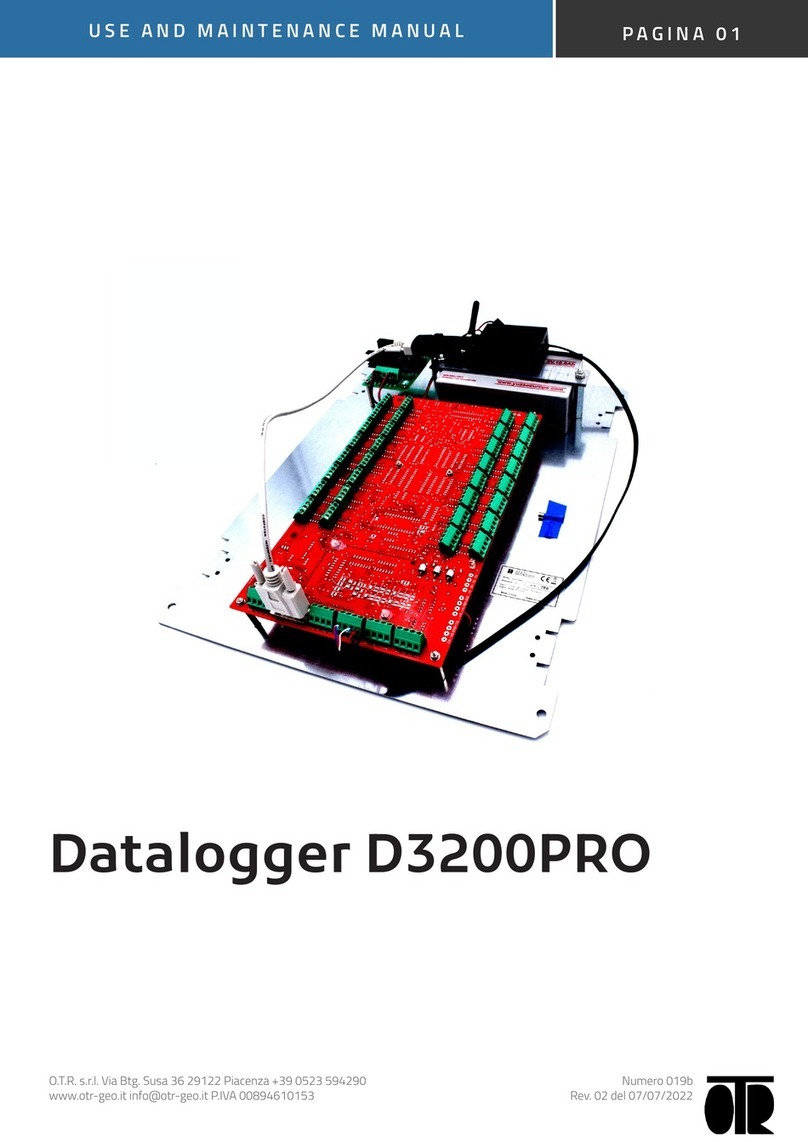
FIS HDL1 User manual

HDL1 & HDL1-G5
Data Logger
Operating Manual


Revision
4 16-
March
-
2007
700
-
HDL1
REVISION HISTORY
Revisi
on #
Date
Description
1
Mar. 23, 2006
Original issue.
2
June 6, 2006
Add new functions
3
Feb
.
6
, 2007
Add GOES antenna & set
-
up information
4
Mar. 16, 2007
Update typographical errors

- i -
Table of Contents
INTRODUCTION
________________________________________________________________
_ 1
POWER
...................................................................................................................................................
1
SENSORS
...............................................................................................................................................
2
TELEMETRY
...........................................................................................................................................
2
DISPLAY
.................................................................................................................................................
2
ENVIRONMENTAL
................................................................................................................................
.2
DATA STORAGE
....................................................................................................................................
2
DATA
...............................................................................................................................................
2
PROGRAM
......................................................................................................................................
3
AUDIT LOG
.....................................................................................................................................
3
TELEMETRY CONFIGURAT
ION
....................................................................................................
3
INSTALLATION
________________________________________________________________
_ 5
PROCEDURE
.........................................................................................................................................
5
DATA LOGGER GROUNDIN
G
.......................................................................................................
5
MOUNTING IN AN ENCLOSURE
...................................................................................................
5
FTS Enclosure...............................................................................................................
5
Other Enclosure.............................................................................................................
6
CONNECTING SDI SENSO
RS
.......................................................................................................
6
CONNECTING AN FTS RA
IN GAUGE
...........................................................................................
6
CONNECTING OTHER FTS
SENSORS
........................................................................................
6
CONNECTING TELEMETRY
DEVICES
.........................................................................................
7
BATTERY CONNECT
ION
...............................................................................................................
7
SOLAR PANEL CONNECTI
ON
......................................................................................................
8
ANTENNA CONNECTIONS
(HDL1
-
G5
only
)
.................................................................................
9
GPS Antenna.................................................................................................................
9
GOES Antenna............................................................................................................
10
CONFIGUR
ING THE DATA LOGGER
TELEMETRY
____________________________________ 13
TOOLBOX SOFTWARE
.......................................................................................................................
13
GET TELEMETRY CONFIG
URATION
................................................................................................
.
13
GET TELEMETRY PORT S
TATUS
......................................................................................................
13
SET UP TELEMETRY POR
T
...............................................................................................................
14
FTS TELEMETRY
.........................................................................................................................
14
GOES / GPS TELEMETRY
...........................................................................................................
15
GALAXY TELEMETRY
..................................................................................................................
17
UNIVERSAL MODEM TELE
METRY
.............................................................................................
19
MCC TELEMETRY
........................................................................................................................
19
GLOBALSTAR MODEM TEL
EMETRY
.........................................................................................
20
GLOBALSTAR MODEM WIT
H GS1 CONTROL BOARD
TELEMETRY
......................................
20

-
ii
-
PROGRAMMING THE DATA
LOGGER
______________________________________________21
PASSWORD PROTECTIO
N
................................................................................................................
21
PROGRAMMING
..................................................................................................................................
21
SYNTAX
........................................................................................................................................
22
A SIMPLE EXAMPLE
....................................................................................................................
22
COMMENTS
................................................................................................................................
.
23
DEFINING TIMERS
......................................................................................................................
23
DEFINING AND USING V
ARIABLES
...........................................................................................
24
MATHEMATICAL OPERATI
ONS
................................................................................................
.
24
INITIALIZING VARIABL
ES
...........................................................................................................
26
DEFINING SDI SENSORS
...........................................................................................................
26
STORING DATA
...........................................................................................................................
27
BUILT
-
IN SENSOR DEFINITION
S
...............................................................................................
28
TESTING VALUES
.......................................................................................................................
29
TRANSMITTING SATELLI
TE DATA
............................................................................................
30
CURRENT CONDITIONS
.............................................................................................................
30
ADVANCED T
OPICS
....................................................................................................................
31
OPERATION
___________________________________________________________________ 35
USING THE DISPLAY
..........................................................................................................................
35
EXTRACTING STORED DA
TA
............................................................................................................
35
TROUBLESHOOTING
.........................................................................................................................
36
AUDIT LOG
...................................................................................................................................
36
SENSORS
.....................................................................................................................................
36
CHANGING AN EXISTING
SETUP
..............................................................................................
36
APPENDIX A
-
SPECIFICATIONS
__________________________________________________37
ENVIRONMENTAL
...............................................................................................................................
37
PHYSICAL
............................................................................................................................................
37
SOLAR PANEL
.....................................................................................................................................
37
BATTERY
.............................................................................................................................................
37
DEDICATED SENSORS
......................................................................................................................
38
SDI
-
12
...........................................................................................................................................
38
RAIN
..............................................................................................................................................
38
DATA STORAGE
................................................................................................................................
.
38
TELEMETRY
........................................................................................................................................
38
HDL1
-
G5 NESDIS APPROVAL
...........................................................................................................
38
CONNECTORS
....................................................................................................................................
39
SOLAR PANEL
.............................................................................................................................
40
BATTERY
......................................................................................................................................
40
SDI
................................................................................................................................................
41
RAIN
..............................................................................................................................................
42
COMPUTER
..................................................................................................................................
43
HDL1
-
G5 GPS ANTENNA CONEC
TOR
......................................................................................
43
HDL1
-
G5 GOES ANTENNA CONN
ECTOR
.................................................................................
43
HDL1 EXTERNAL
TELEMETRY
..................................................................................................
44

-
iii
-
APPENDIX B
-
SENSOR TAG NAMES
______________________________________________ 45
RAIN
......................................................................................................................................................
45
RAIN COUNT
................................................................................................................................
45
POWER
.................................................................................................................................................
45
BATTERY VOLTAGE
....................................................................................................................
45
TELEMETRY VOLTAGE
...............................................................................................................
45
SDI VOLTAGE
...............................................................................................................................
45
TIME
......................................................................................................................................................
46
CURRENT YEAR
..........................................................................................................................
46
CURRENT MONTH
.......................................................................................................................
46
CURRENT
DAY OF MONTH
........................................................................................................
46
CURRENT HOUR
.........................................................................................................................
46
CURRENT MINUTES
....................................................................................................................
46
CURRENT SECONDS
..................................................................................................................
46
CURRENT DAY OF YEAR
............................................................................................................
46
SECONDS SINCE
MIDNIGHT
......................................................................................................
46
SECONDS SINCE START
OF HOUR
..........................................................................................
46
CLOCK
..................................................................................................................................................
47
CLOCK SOURCE
..........................................................................................................................
47

-
iv
-
THIS PAGE INTENTIONALLY LEFT BLANK

- 1 -
INTRODUCTION
HDL1-G5
DATALOGGER
GOES ANTENNA
GND
SDI
RAIN
SDI
GPS ANTENNA
MAIN
MENU
SOLAR PANEL
BATTERY
SDI
SDI
COMPUTER
DATALOGGER
TELEMETRY
GND
SDI
RAIN
SDI
MAIN
MENU
HDL1
BATTERY
SOLAR PANEL
SDI
SDI
COMPUTER
Figure
1.
HDL1 & HDL1
-
G5 Front Panels
The HDL1 and HDL1-G5 are robust, weatherproof programmable data loggers that
support a variety of sensors. Both style data loggers come with an integrated
display, an integrated tempera
ture compensated battery charge regulator, and a front
panel COMPUTER connector (DB9 com port) for standard PC communications.
Many telemetry options (such as telephone, satellite, or radio) are available for
external connection to the HDL1 whereas the HD
L1
-G5 has a built-in high data rate
GOES transmitter. See Appendix A for the detailed specifications on the data logger.
POWER
Power for the data logger is provided by a 12 Vdc sealed lead acid battery connected
to the front panel BATTERY connector. A battery must be connected to the data
logger as the logger will not operate with just a solar panel connected.
With the connection of a solar panel to the data logger front panel SOLAR PANEL
connector, integrated HDL1 power management circuitry provides a method of
regulating and maintaining the most optimal battery charge condition ensuring that
the battery is as fully charged as possible.
A temperature compensated regulator circuit inside the data logger controls Battery
charging. By measuring the battery voltage and temperature the regulator circuitry is
able to apply power from the solar panel to the battery when recharging is required.
In order to ensure the longest possible data logger operation the regulator circuitry is
designed to
minimize current draw and so conserves the energy in the battery.

- 2 -
SENSORS
The data logger provides dedicated connections for four SDI-12 sensors and a
standard FTS tipping bucket style rain gauge.
TELEMETRY
The
HDL1
-G5 is factory configured with an integrated high data rate GOES
Transmitter. The HDL1 is factory configured with an external telemetry connector
which can connect to a variety of FTS telemetry products.
DISPLAY
Both data loggers
come with a built
-
in weatherproof display unit as well as a standard
PC com port connector.
ENVIRONMENTAL
The data logger is watertight, even with no connectors attached. With the exception
of the front panel COMPUTER connector, all the connectors used are circular metal
shell military types that have both color coding and unique sizes and pin-outs that
minimize erroneous connections. The COMPUTER connector is a stainless steel
DB9 com port for easy connection to a local PC.
DATA STORAGE
The data logger actually stores four separate items: the data logger program (DLP);
the data; an audit log; and, telemetry configuration information. Each item is
described further below.
All data logger storage is in non-volatile memory. This means that collected data,
program configuration, and the data logger program are preserved through power
failures and that no backup batteries are needed. If satellite telemetry is used, the
setups for the satellite interface are also saved and are restored when power is
restored. Password protection can be enabled to limit access to functions such as
clearing memory, etc.
DATA
Storage for more than a year of field collected data (typically 87 000 data records
).
Data is stored in a compressed form, with time tags on each record. This is a
circular buffer, so the newest data overwrites the oldest when the memory fills. The
time tags have a resolution of one second and correctly account for leap years.
The data is cleared whenever a new program is loaded. It is possible to explicitly
clear the data; this would be recorded in the audit log.

- 3 -
PROGRAM
8k bytes standard. The application specific data logger program (DLP) is stored in its
origin
al text form in the data logger and then compiled by the data logger. The
original DLP can be retrieved from the data logger at any time.
The stored program is cleared when a new program is loaded. The stored data from
the old program is also cleared at t
his time. A message is put to the audit log when a
new DLP is loaded into the data logger.
AUDIT LOG
2k bytes standard. This is a text record of significant events such as clearing
memory, changing the time, loading a new program, etc. This is a circular buffer, so
the newest messages overwrite the oldest when the buffer fills. Each message is
tagged with a message number and time.
This can not be cleared except by an explicit command. A message will be put to the
audit log after
it is cleared.
TELEMETRY CONFIGURAT
ION
Telemetry port settings for the HDL1 data loggers are stored internally and restored
after power failures. This means, for example, that if you have a GOES interface set
up, it is automatically reconfigured to its previous settings and operation resumes as
soon as the data logger receives a valid time from the GPS clock in the GOES unit.
Telemetry port must be configured according to the telemetry that is being used. See
the "Configuring the Data Logger Telemetry" section for instructions on how to do
this.

- 4 -
THIS PAGE INTENTIONALLY LEFT BLANK

- 5 -
INSTALLATION
PROCEDURE
DATA LOGGER GROUNDIN
G
T
he data logger has built
-
in lightning protection circuitry. This protection can be aided
by the connection from the HDL1 chassis to a single point ground. There is a ground
stud on the HDL1 that will accept #10 ring connector cable mounted inside the
equip
ment enclosure. This ground cable should always be run as low as possible,
and without kinks or sharp bends, to the nearest ground point or radial connection.
On a TTS enclosure, the cable is connected to the enclosure backplate.
In an equipment shed, the
cable is connected to the equipment backplate
or bulkhead which must be strapped to the nearest ground rod.
MOUNTING IN AN ENCLO
SURE
FTS ENCLOSURE
A mounting plate for the data logger will be
fastened to the back of the
enclosure. Decide where you want the data logger (and any other
equipment being installed at this time) to be placed, then just place the
data logger over the appropriate keyhole slots and slide it down into
place.
AUTOSAMPLER
TELEMETRY
MENU
MAIN
GROUND
SDI
B
A
T
T
E
R
Y
SDI
GND
TTS ENCLOSURE
BATTERY
HDL1
DATALOGGER
OPTIONAL TELEMETRY DEVICE
SDI
RAIN
SDI
S
O
L
A
R
P
A
N
E
L
C
O
M
P
U
T
E
R
HDL1
D
A
T
A
L
O
G
G
E
R
T
E
L
E
M
E
T
R
Y
TX
T
R
A
N
S
C
E
I
V
E
R
G
L
O
B
A
L
S
T
A
R
RX
GPS A
NTENNA
Figure
2.
FTS Equipment Enclosure
Connect a grounding wire to the data logger ground stud.
If you are using FTS provided telemetry, then power can be
provided to the telemetry device through the telemetry
connector and no separate power connection is required.
Connect the data logger to power, telemetry and sensors as
needed.

- 6 -
OTHER ENCLOSURE
Depending on the nature of the enclosure, either a keyhole mounting plate can be
fastened to one wall of the enclos
ure or a sheet of plywood can be used. In this case
you will need a set of the mounting adapters.
Remove the screws from the back of the data logger and use them to fasten the
mounting adapters to the data logger case. You can then fasten the adapters to the
plywood using wood screws.
Connect a grounding wire to the data logger ground stud.
CONNECTING SDI SENSO
RS
SDI sensors from a variety of manufacturers are supported. If the sensor was
supplied by FTS then it will have been programmed to its final parameters and
system address, otherwise you will need to remember to program the sensor to its
final address and set up any programmable characteristics (i.e. units) that you need.
The procedure to do this varies from ma
nufacturer to manufacturer.
Remember to set the sensor command and address in the data logger program to
match that set into the sensor. Incorrect or missing readings will result if this is not
done correctly.
Sensors supplied by FTS have a 3 pin waterproof connector attached, so all that is
necessary to set it up is to plug it in to the data logger.
If you have a sensor with bare wires then it will be necessary to solder the correct
connector to the cable. See Appendix A for the correct connector and pin
-
out.
CONNECTING AN FTS RA
IN GAUGE
The FTS tipping bucket rain gauge connects directly into the matching connector on
the data logger. The front panel RAIN connector is color coded with a blue ring to
correspond w
ith the blue ring on the rain gauge cable.
See the section Built-in sensor definitions for the various readings available from
this sensor. Connector pin-out is defined in Appendix A, along with the input
specifications.
CONNECTING OTHER FTS
SENSORS
FTS Forest Technology Systems can also supply a variety of other sensors including:
Wind speed and wind direction
Air temperature and humidity
Fuel stick moisture and temperature
Visibility
Solar Radiation
Barometric P
ressure
Etc.
Please contact FTS for further information on integrating the above sensors with the
HDL1
d
ata
l
ogger.

- 7 -
CONNECTING TELEMETRY
DEVICES
The HDL1 data logger can supply power to externally connected telemetry devices.
For proper telemetry operation, the HDL1 telemetry port must be configured
appropriately for the desired telemetry device using the Toolbox software provided by
FTS.
If you are attaching your own telemetry, the telemetry connector signals and
pin
-
outs are given in Appendix A.
The HDL1-G5 logger comes with its internal telemetry port preconfigured for GOES
operation.
BATTERY CONNECTION
The HDL1 is designed to work with a 12 Vdc lead acid type battery. A battery m
ust
be connected to the data logger as the logger will not operate from just a solar panel.
The HDL1 battery cable (CBL-
HDL
-
BAT
-1) is a 6 pin connection that connects to the
front panel BATTERY connector. In addition to providing the battery power
connect
ion, the cable has an integrated temperature sensor which is used to sense
the battery temperature.
Temperature compensation is achieved by the regulator circuitry measuring the
battery voltage and the battery temperature and applying a correction of
app
roximately
-
0.03 volts per degree C. That is, for every 1 degree C that the battery
temperature rises above the 25 degree C level, the charge voltage that the regulator
switches off at is reduced by 0.03 volts.
The battery voltage can be monitored by the data logger and returned to the user
either through the attached telemetry device, the display unit or the COMPUTER
port.
Battery connector signals and pin
-
outs are given in Appendix A.
The HDL1 battery connection procedure is as follows:
CAUTION:
The
fuse will blow if the battery is connected backwards
1.
Connect the Battery cable to the battery. The red wire with the fuse
holder goes to the positive (+) side of the battery. The black wire goes
to the (-) side of the battery. The connections are made by
bolting
each of the cable ring lugs to the appropriate battery terminal.
2.
Mount the temperature sensor to the battery by taping it to the top of
the battery using foam tape or duct seal putty. The sensor is mounted
between the two battery posts.
3.
Route the cable around behind the shelf above the battery, and plug
the 6 position connector into the HDL1 front panel BATTERY
connector.
4.
Once the battery is connected properly, connect the cable from the
charging power source (typically the solar panel) to the HDL1
.
5.
Verify the battery connection by reading the battery voltage on the
HDL1 display.

- 8 -
SOLAR PANEL CONNECTION
The HDL1 is designed to work with a range of solar panels. Solar panels (20 & 50W)
are supplied pre-wired from FTS with the appropriate connector. The appropriate
sized solar panel is site specific and depends on solar exposure and overall power
requirements. The HDL1 does not require a solar panel in order to operate.
Please contact FTS for assistance with power budget / solar panel sizing
estimations.
If you are attaching your own solar panel, the SOLAR PANEL connector
specifications, signals and pin
-
outs are given in Appendix A.

- 9 -
AN
TENNA CONNECTIONS (H
DL1
-
G5
only
)
For proper operation, the HDL1-G5 requires that a GPS antenna and a GOES
antenna be connected to the data logger
(see Figure 3)
.
HDL1-G5
DATALOGGER
GOES ANTENNA
GND
SDI
RAIN
SDI
GPS ANTENNA
MAIN
MENU
SOLAR PANEL
BATTERY
SDI
SDI
COMPUTER
Figure
3.
HDL1
-
G5 Antenna Connections
GPS ANTENNA
The GPS antenna is used by the
HDL1
-
G5
s internal G
OES
transmitter to acquire
time synchronization, frequency stability, and location information from the Global
Positioning System. The internal GOES transmitter will not transmit until it has
acquired a GPS fix so it is important that the GPS antenna is mounted securely in a
location where it won t be damaged or covered by snow and where it has adequate
exposure to the sky. The GPS antenna must be the 3.3V active type, and have a
SMA connector for attaching to the
HDL1
-G5 data logger
.
FTS su
pplies two types of
GPS antenna
s that are suited to particular applications.
The first
type
is used in applications where snow cover isn t likely to be a problem
and where an electronics cabinet is used to contain the data logger, station power
supply
, and other equipment. This antenna is mounted through a hole in the top of
the electronics cabinet and connects to the data logger inside the cabinet using a
short coaxial cable. When installing this antenna, m
ake sure that the
antenna
seal is
seated properly between the antenna body and the outside
cabinet
surface
before
tighten
ing the antenna s l
arge retaining nut.
The second
type
of antenna is used in geographic areas that get significant
accumulations of snow. This antenna has a plastic radome that is d
esigned
to shed
snow that could cover the antenna and block the GPS signal
.
For
installation of
this
type of
antenna,
a short antenna support arm must first be clamped to a pole such as
a wind sensor mast, or screwed to the side of the building. Next pass the end of the
antenna cable with the TNC connector up through the mounting tube at the outboard
end of the support arm and
attach
it to the connector on the underside of the
antenna. Finally, screw the antenna down onto the threads on the mounting tube
(hand
-tight) and route the cable back to the data logger location using suitable cable
protection and tie straps where appropriate.
Connect the GPS antenna cable to the HDL1
-
G5 by threading the connector onto the
SMA
-
Type GPS antenna jack on the HDL1
-
G5
front panel.
GPS ANTENNA CONNECTOR
(female SMA)
GOES ANTENNA CONNECTOR
(female N type)

-
10
-
GOES ANTENNA
The GOES antenna is used by the HDL1-G5 s internal transmitter to transmit to the
signal to the GOES satellite. The GOES antenna is a 50 ohm, Yagi antenna with
right hand circular polarization, 11dBic gai
n and a nominal VSWR of 1.5.
The following procedure details the
mounting procedure for the
GOES Antenna.
#1#2#3#4#5
Connector should always
face down when antenna
is mounted.
#1 - D3
#2 - D2
#3 - D1
#4 - DE
#5 - R
Figure
4.
The GOES Antenna
1.
Install the two U-bolts in the mounting bracket, using four split lock washers and
four 5/16 hex nuts.
2.
Attach
the antenna to the mounting bracket using two 3/8 x 2" bolts, four external
tooth lock washers, and two 3/8 nuts.
3.
Conductive grease that is compatible with aluminum is applied to the antenna
element threads. Attach the elements finger-tight to the antenna boom. There is
a number stamped on the end of each element. Beginning at the end and
working toward the mount, install elements 1, 2, 3, 4 and 5 in order.
4.
Mount the antenna assembly on a vertical pipe to allow for accurate angle
adjustment. The antenna must be free to rotate around the pipe so it can be
aimed at the satellite once the GPS
receiver
has synchronized with the GPS
satellites.
5.
Inclination and bearing required to properly align the antenna with the satellite
can be found using the front panel of the HDL1-
G5
. Start by pressing the red
MAIN MENU button on the
HDL1
-G5 front panel. Then select E: Telemetry
Information followed by Antenna . The bearing information shown on the
HDL1
-G5 display (see Figure 5) is for true north and will need to b
e
adjusted for
magnetic north based on the installation area.

-
11
-
Alternately, the antenna bearing information can be obtained using the Get
Telemetry
Port
Status Toolbox command. Again it will be necessary to adjust
the compass heading given from true north to magnetic north based on the
installation area.
Note that the GPS must have acquired its timing synchronization and location
information before bearing
and inclination are displayed.
Figure
5.
Inclination and Be
aring Screen
6.
After adjusting the true north bearing for the local magnetic variance, direct the
GOES antenna toward the satellite by tilting it up to the correct angle and rotating
it around the vertical pipe to the adjusted bearing
(see Figure 6)
.
F
igure
6.
GOES Antenna
A
djusted for
S
atellite
C
ommunications
7.
Connect the GOES antenna cable to the N-type connector on the antenna. This
critical connection should be wrapped with waterproof, self-vulcanizing tape,
meltable wall heat shrink tubing or equivalent to prevent the possible entry of
water that could degrade the signal and cause corrosion to the connection.
8.
Connect the other end of the cable to the HDL1-
G5 internal GOES transmitter by
threading the connector onto the N-type GOES antenna jack on the HDL1-
G5
front panel.

-
12
-
THIS PAGE INTENTIONALLY LEFT BLANK
This manual suits for next models
1
Table of contents

