ADAPCO Guardian 95 G4 User manual

GUARDIAN MODEL
95 G4
©2017
GUARDIAN ULV EQUIPMENT
PRODUCT OF ADAPCO, INC.
2
REMEMBER – YOUR ULV COLD FOG GENERATOR IS ONLY AS SAFE AS
THE OPERATOR!
Hazard control and accident prevention are dependent upon the awareness, concern,
prudence, and proper training of the personnel involved in the operation, transport,
maintenance, and storage of the equipment.
FAILURE TO FOLLOW SAFE OPERATING PRACTICES
MAY RESULT IN INJURY
• Keep all shrouds and guards in place especially the drive belt shroud.
• Before performing any maintenance or service, stop the machine and
disconnect the battery.
• Keep hands, feet and clothing away from power-driven parts.
• Read this manual completely as well as other manuals that come with this
equipment.
• Use ear protection when in close vicinity of equipment when powered up.
• UDo NotU direct air blast from nozzle directly at any part of your body.
• Use appropriate PPE when loading tanks and performing calibrations.
This manual covers the operating instructions and
illustrations for:
Guardian 95 G4 (Std. Fixed Flow ULV Sprayer)

3
TABLE OF CONTENTS
MODEL 95 G4
Contents
SPECIFICATIONS ...................................................................................................................................... 5
GENERAL INFORMATION ......................................................................................................................... 7
INTRODUCTION ................................................................................................................................... 7
SERVICING THE ENGINE ....................................................................................................................... 7
DIRECTION REFERENCE ........................................................................................................................ 8
GENERAL SAFETY INFORMATION ......................................................................................................... 9
SIGNAL WORDS ................................................................................................................................. 10
BEFORE OPERATION CONSIDERATIONS ............................................................................................. 11
OPERATION CONSIDERATIONS .......................................................................................................... 12
MAINTENANCE AND STORAGE .............................................................................................................. 14
FAMILIARIZATION ................................................................................................................................. 15
OPERATOR CONTROLS ....................................................................................................................... 15
AIR PRESSURE GAUGE ....................................................................................................................... 16
PRESSURE SWITCH ............................................................................................................................ 16
FORMULATION FILTER ....................................................................................................................... 16
FORMULATION TANK ........................................................................................................................ 16
INSECTICIDE PUMP ............................................................................................................................ 17
PULSE DAMPENER ............................................................................................................................. 17
FLUSH TANK AND VALVE ................................................................................................................... 17
ATOMIZATION NOZZLE ...................................................................................................................... 17
INSTALLATION ....................................................................................................................................... 18
COLD FOG GENERATOR (ULV SPRAYER) CONTENTS ........................................................................... 18
FACTORY FLUID LEVELS ..................................................................................................................... 19
VEHICLE INSTALLATION ..................................................................................................................... 20
ENGINE STARTING ............................................................................................................................. 22
Key Start ........................................................................................................................................ 23

4
Recoil Start .................................................................................................................................... 24
Remote Pendant Start ................................................................................................................... 24
MAINTENANCE ...................................................................................................................................... 24
CHECKING ENGINE CRANKCASE OIL LEVEL ......................................................................................... 24
CHANGING ENGINE CRANKCASE OIL .................................................................................................. 25
ENGINE AIR CLEANER ........................................................................................................................ 25
BLOWER LUBRICATION ...................................................................................................................... 26
CLEANING THE MACHINE .................................................................................................................. 26
BELT TENSION ................................................................................................................................... 26
CALIBRATION ........................................................................................................................................ 29
FLOW CALIBRATION FMI PUMP ......................................................................................................... 29
DROPLET SPECTRUM CALIBRATION ................................................................................................... 30
FLOW DIAGRAM .................................................................................................................................... 32
TROUBLESHOOTING .............................................................................................................................. 32
NOTES: .................................................................................................................................................. 34
GUARDIAN 95 G4 ULV 1-YEAR LIMITED WARRANTY .............................................................................. 35
Appendix A:........................................................................................................................................... 37
Appendix B: ........................................................................................................................................... 38

5
SPECIFICATIONS
Guardian 95 G4
Engine
Make Kohler
Model Command PRO CH395-3031
Horse Power 9.5
Engine Type Air cooled, 4-stroke, OHV, Single cylinder
Bore & Stroke 78 x 58 mm (3.1 x 2.3 in)
Displacement 277 cc (16.9 cu. In)
Ignition System Solid-state
Direction of Rotation Counterclockwise facing the PTO shaft
Starting System Electric start
Charging System 10 A
Dry Weight 27.8kg (61.5 lbs.)
Fuel Unleaded gasoline
Safety Switch Low oil shutdown
Blower
Make Dresser Roots
Model URAI-33UJ
Dia. Outlet/Inlet 2”- S
Max Performance 3550 RPM
9 PSIG=169 CFM
4 PSIG=186 CFM
Configuration Horizontal mount
Left hand drive facing the PTO shaft
Weight 69 lbs.
Shaft Diameter 0.75 (3/4”)
Paint Black
Drive Couple
Method Belt, banded double V
Typical Size 2/3VX425
Nozzle
Model “VAAT” (Vectored Air Atomization Technology”
Size 2” pipe
Material Aluminum 6061-T6
Chem. Feed Rear center, 3/8” OD tube, 1/4” NPT
No. of Pieces 2, nozzle body, nozzle hood
Mounting 3.25” OD flange, 2.85” 4-hole bolt pattern
Equally spaced, 1/4-20 fasteners
Nozzle Rotation 360º horizontally, 360º vertically
Capacity
Fuel 1.5 Gallon standard
Formulation 15 Gallon (56.7 liters)

6
Lockable formulation tank cap or non-lockable, std option
Flush 1 quart (1.42 liter)
Chemical Pump
Make FMI for fixed or variable flow
Model QB
Type Positive displacement Piston
Piston 3/8” ceramic
Flush valve
Configuration 3-way diverter
Power 12V dc
Consumption 7 watts
Cut-Off Valve
Material Stainless
Rating 5 lbs
Gauges
Pressure 0-15 PSI, glycerin filled, panel mounted
with pressure switch pump lockout
Throttle Control
Throttle Solenoid actuator 12V dc
Choke Control
Choke Solenoid actuator 12V dc
Finish
Type Epoxy Powder Coat chassis
Dimensions
Length 37.8”
Width 29.8”
Height 28” horizontal, 32.9” nozzle pointed vertical
Weight 340 lbs. (dry)

7
GENERAL INFORMATION
INTRODUCTION
Your ULV cold fog generator, known from this point on in this manual as “ULV Sprayer”, was built
to the highest standards in the industry. However, the prolonged life and maximum efficiency of
your sprayer equipment depends on you following the operating, maintenance and adjustment
instructions in this manual.
If additional information or service is needed, contact ADAPCO or if applicable, your authorized
ADAPCO service representative.
We encourage you to contact ADAPCO for repairs. As the designer and manufacturer of this
equipment, ADAPCO professionals are informed and trained on the latest methods to service this
equipment and provide prompt and efficient service in the field or at the service shop and carry
a full line of Guradian ULV service parts and accessories.
THE REPLACEMENT OF ANY PORTION THIS PRODUCT BY OTHER THAN THE
MANUFACTURER’S AUTHORIZED REPLACEMENT PART MAY ADVERSELY AFFECT THE
PERFORMANCE, DURABILITY OR SAFETY OF THIS PRODUCT. USE OF OTHER THAN
ADAPCO/GUARDIAN ULV REPLACEMENT PARTS WILL VOID THE WARRANTY.
For some pictoral clarity, some illustrations and fugures in this manual may show shields, guards,
or shrouds removed. Under no circumstances should your ULV sprayer be operated without
these devices in place.
All information is based upon product information available at the time of approval for printing.
ADAPCO, Inc. reserves the right to make changes at any time without notice and without
incurring any obligation.
SERVICING THE ENGINE
The detailed servicing and repair of the engine is not covered in this manual; only routine
maintenance and general service instructions are provided. For service of the engine during the
limited warranty period, it is important to contact ADAPCO and if applicable, an authorized
ADAPCO service representative or an authorized servicing agent of the engine manufacturer.
UAny unauthorized work done on the engine during the warranty period may void your
warranty.
8
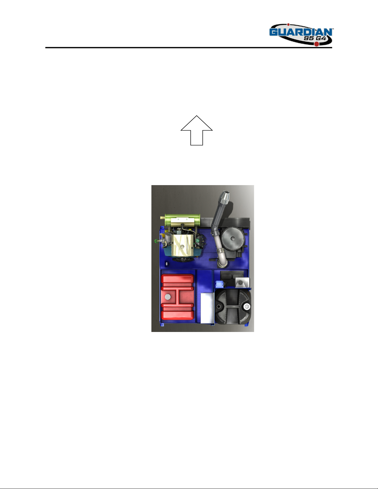
DIRECTION REFERENCE
The “Right” and “Left”, “Front” and “Rear” of the machine are refereced from the operator’s right
and left when standing behind the vehicle and facing in the normal forward direction of the
vehicle. Additionally, the ULV sprayer is designed to be placed in the back of a vehicle with the
engine and blower closest to the rear bumper of the vehicle.
Forward
Rear
Left
Right
9
SAFETY INFORMATION
GENERAL SAFETY INFORMATION
UYour ULV sprayer is only as safe as the operator. Carelessness or operator error may result in
serious bodily injury or death.U Hazard control and accident prevention are dependent upon the
awareness, concern, prudence, and proper training of the personnel involved in the operation,
transport, maintenance, and storage of the equipment. UMake sure every operator is properly
trained and throughly familiar with all of the controls before operating this spray equipment. The
owner/user can prevent and is responsible for accidents or injuries occurring to the themselves,
other people or property.
A replacement copy of this manual is available from ADAPCO, Inc. or if applicable, an authorized
dealer or reseller of this equipment at:
ADAPCO, Inc.
Attn: Customer Service Department
550 Aero Lane
Sanford, FL 32771
Or call 1-800-367-0659
Additionally, a copy of this manual can be downloaded from the ADAPCO website at
HUwww.MyADAPCO.comUH by using the model number.
READ THIS OPERATOR’S MANUAL
BEFORE ATTEMPTING TO START
OR USE THIS SPRAYER.
10
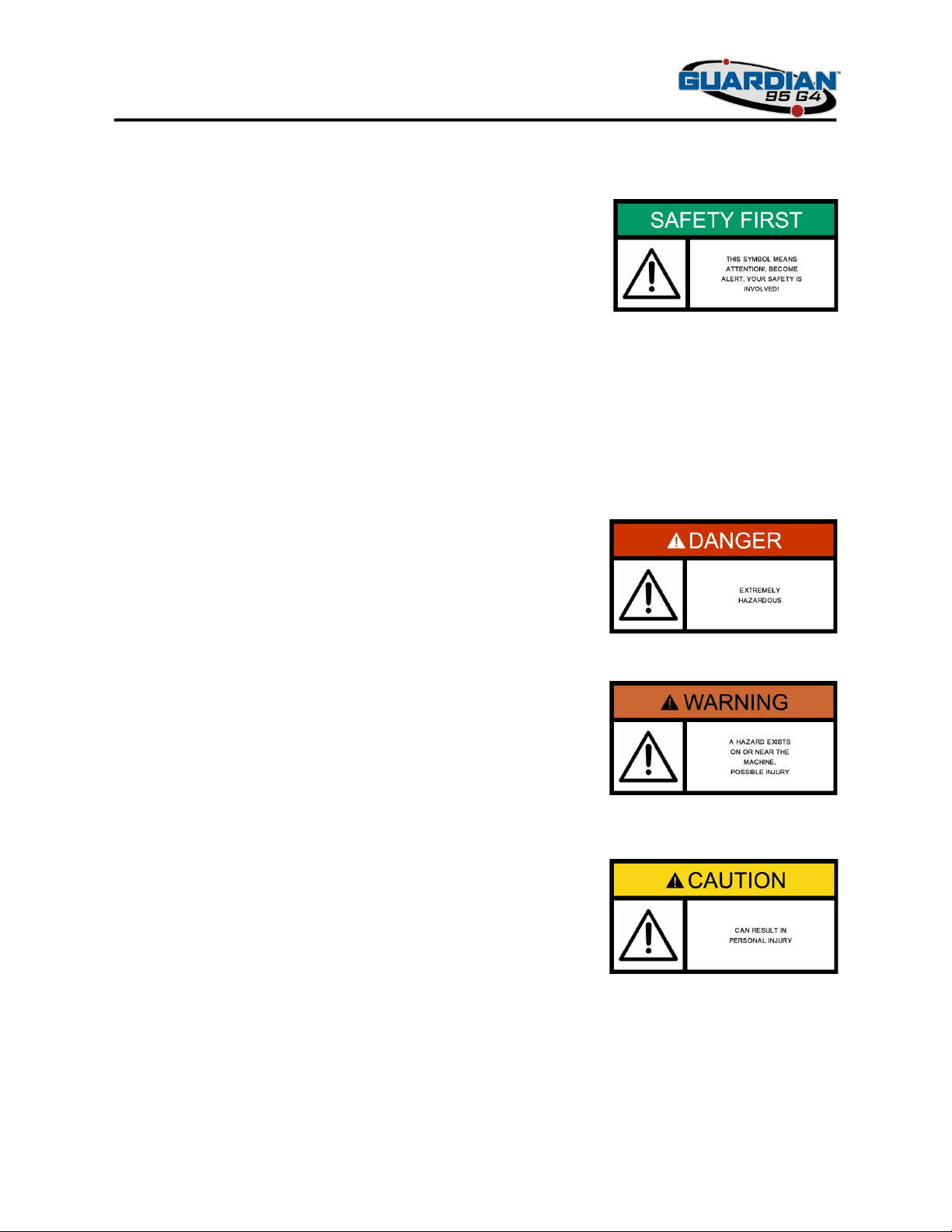
SIGNAL WORDS
This general symbol means “Attention! Become Alert! Your
Safety is involved!” The symbol is used with the following signal
words to attract your attention to safety messages found on the
decals on the machine and throughout this manual.
The message that follows the symbol contains important information about safety. To avoid
injury and possible death, carefully read the message! Be sure to understand the causes of
possible injury or death.
Signal Word
The Signal word is a distinctive word found on the safety decals on the machine and throughout
this manual that alerts the viewer to the existence and relative degree of the hazard.
The signal word “DANGER” denotes that an extremely
hazardous situation exists on or near the machine that could
result in high probability of death or irreparable injury if proper
precautions are not taken.
The signal word “WARNING” denotes that a hazard exists on or
near the machine that can result in injury or death if proper
precautions are not taken.
The signal word “CAUTION” is a reminder of safety practices on
or near the machine that could result in personal injury if proper
precautions are not taken.
Your safety and the safety of others depend significantly upon your knowledge and
understanding of all correct operating practices and procedures of this machine.
11
BEFORE OPERATION CONSIDERATIONS
1. Become familiar with the safe operation of the ULV sprayer and the operator controls.
2. Never allow children to play on or with the machine. Never allow children to ride in a
vehicle sitting next to or on top of this machine.
3. Always wear appropriate clothing while operating, maintaining, servicing or calibrating
this machine. The wearing of such items as safety glasses, aprons, gloves, and safety
shoes is advisable and may be required by some local ordinances or insurance regulations.
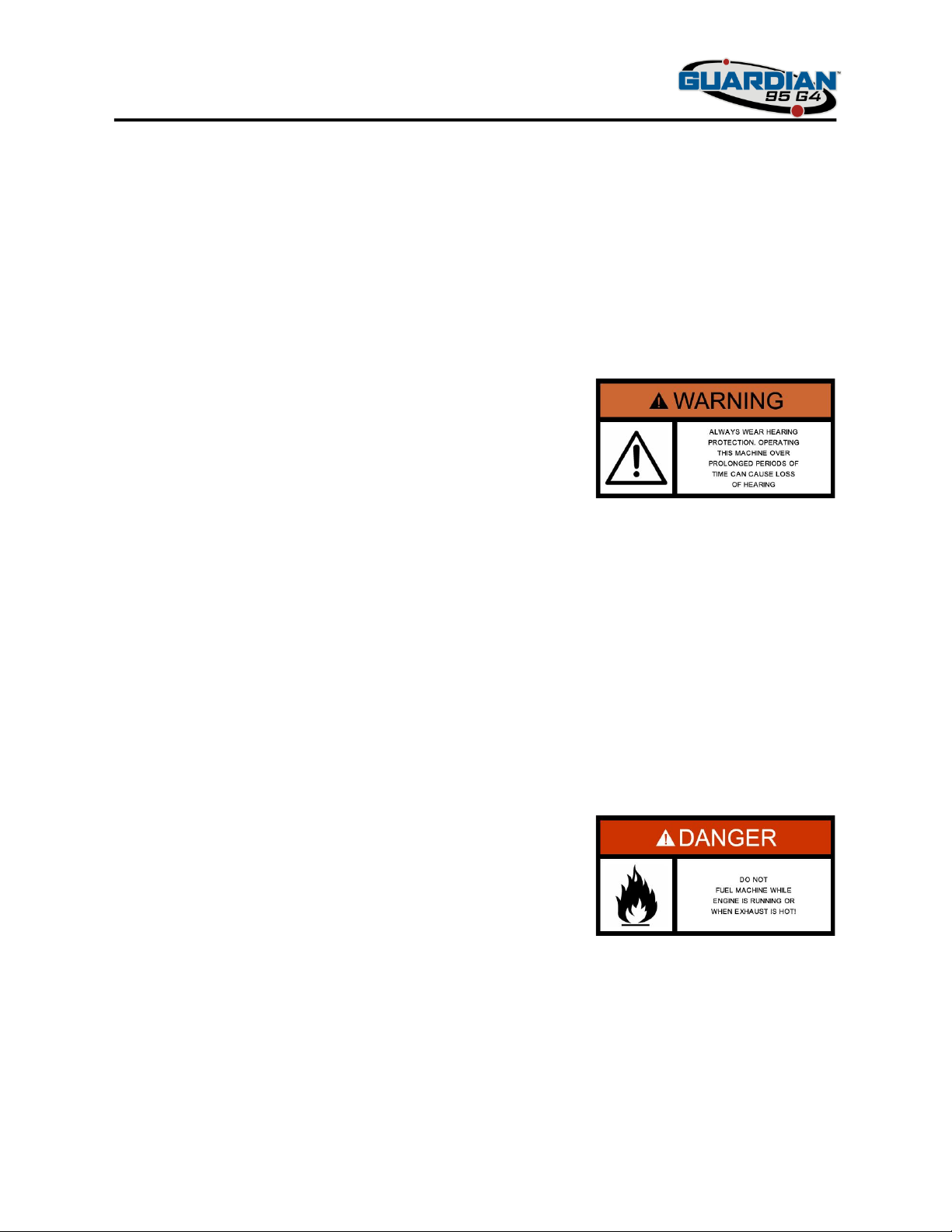
4. Always wear hearing protection. Operating this machine for prolonged periods of time
without hearing protection can cause permanent loss of hearing.
5. Keep the Spray machine and attachments in good operating condition. Keep all shields,
guards, or shrouds in place. If a shield, safety device or decal is defective or damaged,
repair or replace it before operating the machine.
6. Fill the fuel tank with clean, fresh, unleaded gasoline with a minimum octane rating of 87.
To avoid personal injury or property damage, use extreme care in handling gasoline.
Gasoline is extremely flammable and the vapors are explosive.
a. Keep flammable objects (cigarettes, matches, etc.), open flames and sparks away
from the fuel tank and fuel container.
b. Use only an approved gasoline container.
c. DO NOT add fuel to a running or hot engine. Allow the engine to cool for several
minutes before adding fuel.
d. Never fuel the machine indoors or in a small enclosed area without ventilation.
e. Never store the sprayer or fuel container where there is an open flame, spark or
pilot light such as on a water heater or other appliance.
f. Never fill containers inside a vehicle or on a truck or trailer bed with a plastic bed
liner. Always place the container on the ground away from your vehicle before
filling.
12
g. Keep the nozzle in contact with the rim of fuel tank or container opening at all
times until fueling is complete. We recommend not using a nozzle lock-open
device.
h. If fuel is spilled on clothing, change clothing immediately.
i. Replace gas cap and tighten securely.
7. Fill chemical tank to the indicated full level not to exceed 15 U.S. gallons.
a. Keep fill nozzle securely in the opening at all time while chemical is being
transferred. We recommend not using a nozzle lock-open device.
b. Wear appropriate personal protective equipment while filling chemical tank as
required by the specific label of the product being filled.
c. Ensure chemical tank filling is accomplished in a well ventilated area.
d. Affix an approved label to the chemical tank indicating its contents after filling.
e. Thoroughly clean hands after handling chemical filling equipment.
OPERATION CONSIDERATIONS
1. DO NOT permit untrained personnel to operate the machine.
2. Before operating this sprayer, familiarize yourself with all sprayer functions and
engine controls. Knowing the location, function and operation of these controls is
important for safe and efficient operation.
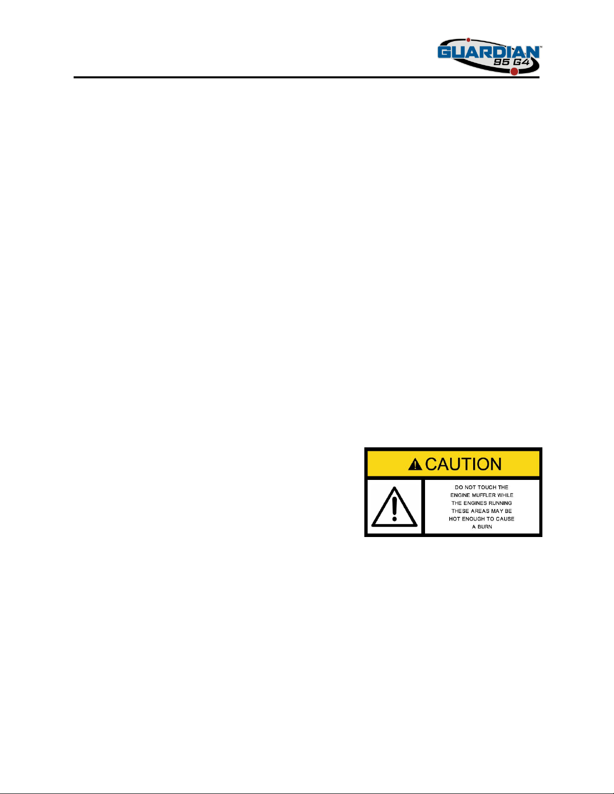
3. DO NOT touch the engine muffler or any part of the exhaust system while running;
wait several minutes for the engine and exhaust to cool and check for heat before
doing so.
4. Blower housing and tubing to the nozzle including swivel elbows and nozzle become
very hot during prolonged operation. DO NOT touch any of these areas while running;
wait several minutes allowing these components to cool before touching.
5. DO NOT operate the engine without the blower intake air filter housing being
installed. Debris, cleaning rags or clothing can be sucked into the blower causing
potential damage to the blower or injury to operators.
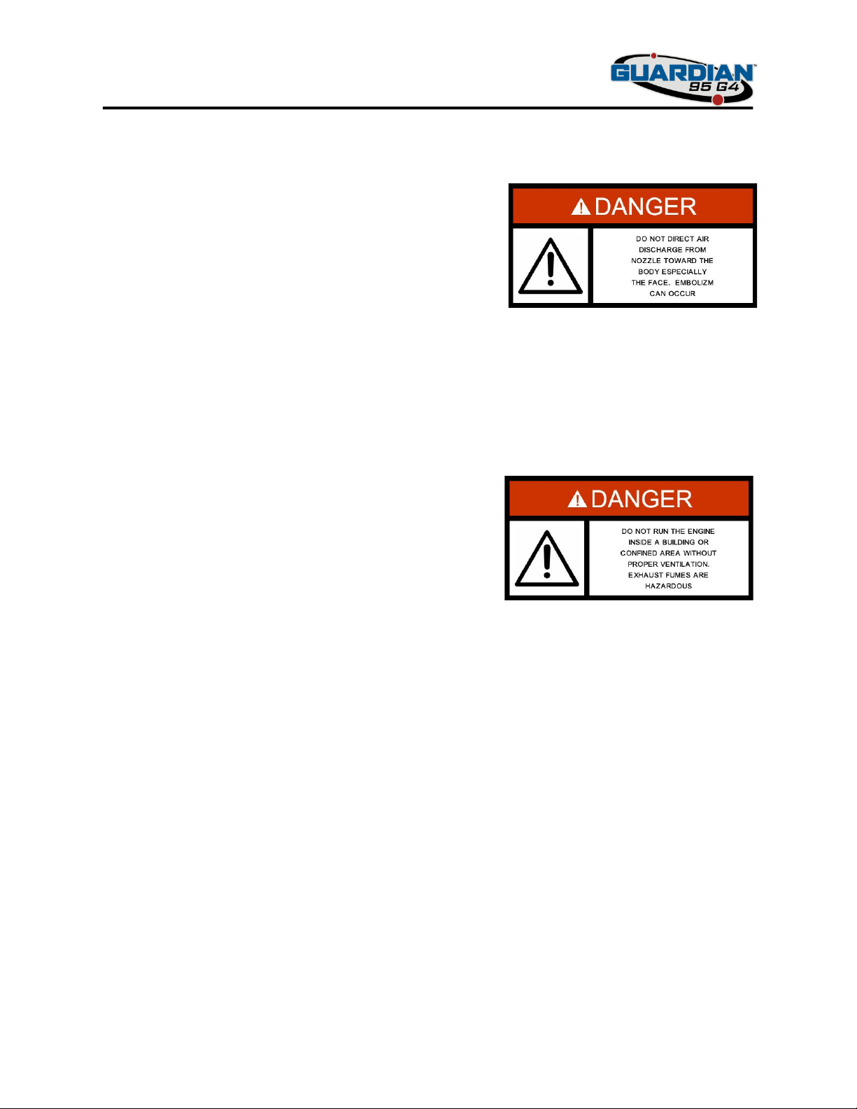
6. DO NOT direct the air blast from the nozzle at any portion of the body and especially
the face. High volume air can penetrate the skin and cause serious injury even death.
Always point the nozzle in an upward- attitude when sprayer is running and above
13
head level for those on the ground. It is not recommended for anyone to be standing
above the level of the nozzle when running even if the machine is mounted securely
on a vehicle.
7. NEVER walk directly into the air/chemical blast from the nozzle when insecticide or
any other formula is being atomized.
8. DO NOT direct the air/chemical discharge toward bystanders or allow anyone near
the machine while in operation.
9. DO NOT run the engine inside a building or a confined area without proper ventilation.
Exhaust fumes are hazardous and contain carbon monoxide which can cause brain
injury and death.
10. DO NOT operate the machine under the influence of alcohol or drugs.
11. Use care when loading or unloading the machine onto a truck or trailer.
12. Do not change the engine governor settings to over-speed the engine. See the engine
operator’s manual for information on engine settings.
13. NEVER leave the machine running unattended.

14
MAINTENANCE AND STORAGE
1. Allow only trained personnel to service the ULV spray machine.
2. Park the vehicle or place the machine on level ground for fluid level verification.
3. Never make adjustments to the machine with the engine running unless specifically
instructed to do so. If the engine is running, keep hands feet and clothing away from
moving parts.
4. Stop engine and remove or disconnect spark plug wire(s) to prevent accidental
starting of the engine when servicing or adjusting the machine. Wait for all movement
to stop before adjusting, cleaning or repairing.
5. Keep all nuts, bolts and screws tight, to ensure the machine is in safe working
condition.
6. The engine must be shut off before checking the oil or adding oil to the crankcase.
7. Let the engine cool before storing.
8. DO NOT store the machine near an open flame.
9. Shut off fuel while storing or transporting.
10. To shut off engine for prolonged periods of time or seasonal storage, drain the fuel
tank, start the engine and let the engine run out of fuel before storing.

15
FAMILIARIZATION
OPERATOR CONTROLS
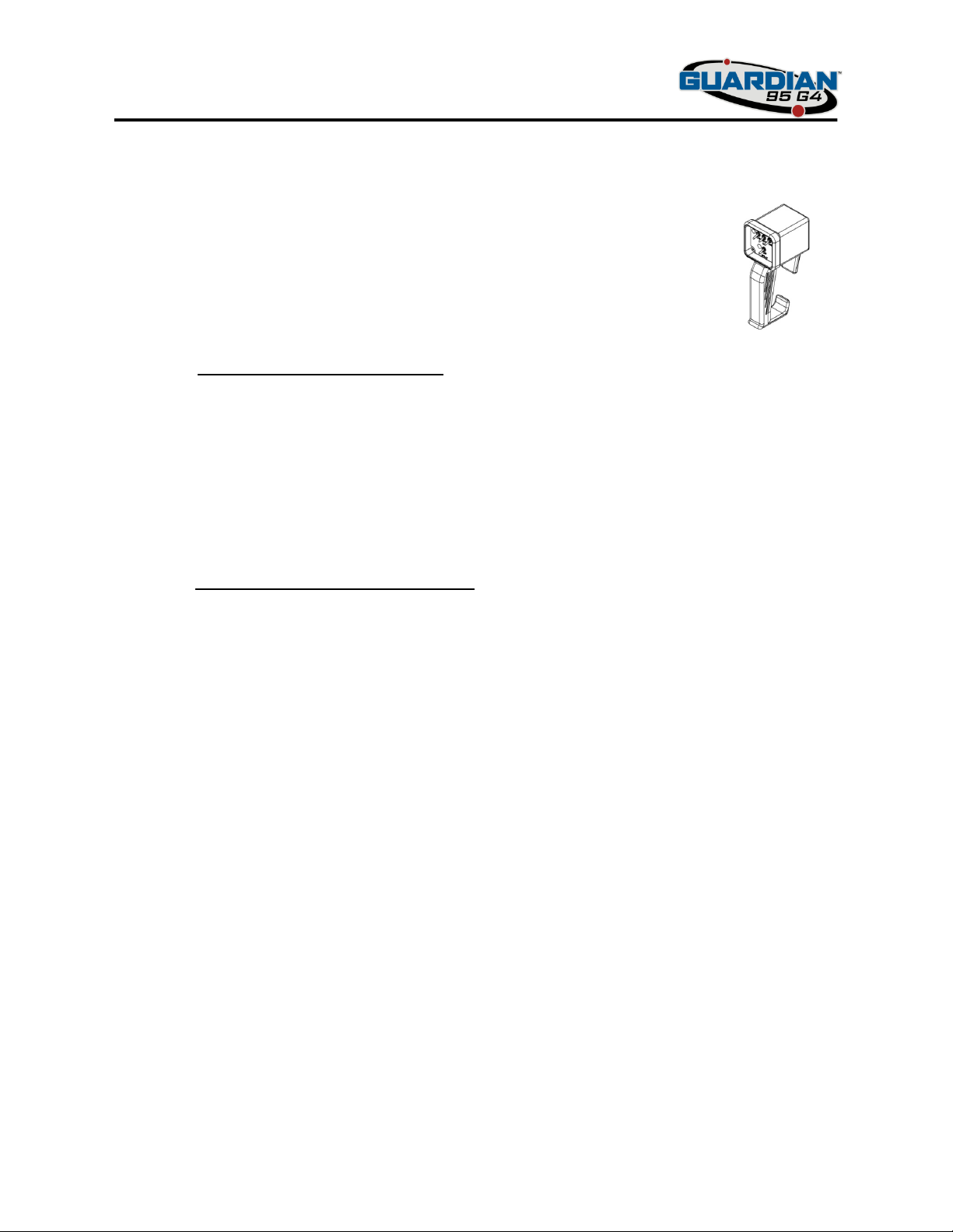
The below illustration shows the standard operator control pendant and its functions:
1. Power switch when asserted (turned on) applies
power to the control pendant as well as provides
operating voltage to allow fuel flow to the engine.
2. RED LED (Light Emitting Diode) when illuminated
implies the power switch has been turned on and
ready to receive commands.
3. Engine on-off-start switch is a 3 position switch that
controls the status of the sprayer’s engine. When in
the OFF position, a control voltage is sent to the relay
beside the engine. When this relay is energized, the engine’s ignition system is shorted
to Ground. When in the ON position, the engine is ready to run and the ignition is ready.
The START position is a spring loaded momentary switch that engages the engines starter
motor and will continue to engage the starter until the engine is started or the switch is
released.
4. Flush switch when in the ON position sends a control voltage to the 3-way electric
solenoid valve which is connected to both the flush tank and the main formulation tank.
Selecting the flush ON position selects the contents of the flush tank to be pumped
through the insecticide pump when the spray switch is turned on.
5. Yellow LED when illuminated implies the flush tank has been selected.
6. Spray on/off switch turns the insecticide pump on and off when this switch is asserted. If
the sprayer is running (engine on) and the spray switch is asserted, the pump will begin
to run at a calibrated rate. If the engine is not running and the toggle switch on the pump
electronic enclosure is in the down position, the pump will not run when the spray switch
is turned on.
Additionally, the Spray on/off switch when asserted applies a control voltage to the
throttle solenoid (if equipped) increasing engine RPM to a preset (mechanical) position.
When the Spray switch is turned off, the engine reduces to an idle speed. Once ULV
sprayer is warmed up, the throttle should be set to the desired RPM or pressure at which
the applicator wishes to atomize the chemical material.
7. Green LED when illuminated implies the pump switch is in the ON position and if the
sprayer is running, the pump will run and insecticide or flush solution will flow through
the sprayer to be atomized.
16
AIR PRESSURE GAUGE
The air pressure gauge is a glycerin filled type with a pressure
range from 0-15 psig. When the engine is running and throttle
adjusted to the desired engine RPM, atomization nozzle back
pressure is most often the overriding factor in assuring correct
atomization of a given flow rate or range of flow rate. Back
pressure is measured from a fitting on the cross over tube
through a short flexible hose to the gauge.
PRESSURE SWITCH
A pressure switch is located on the side wall of the “Wet” section of this ULV sprayer. Attached
to it is a section of flexible hose back to a fitting located on the crossover tube. The purpose of
this pressure switch is to ensure the insecticide pump cannot be inadvertently turned on without
sufficient air pressure. If this was to occur, the pressure switch does not allow the circuit to
“make” thus the insecticide pump will not run. The pressure switch can be overridden by
asserting the toggle switch on the back end of the pump’s electronic enclosure (toggle up)
allowing the pump to run regardless if back pressure is present or not.
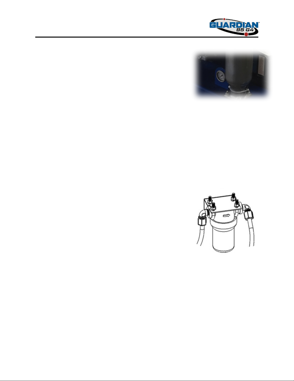
FORMULATION FILTER
Products to be atomized through this ULV sprayer must be
filtered before it is drawn through the insecticide pump to ensure
uniform fluid consistencies and prevent contamination and
potential particulate damage. The glass filled polypropylene
filter assembly consists of 4 pieces; top, bottom, gasket, and
stainless steel 80 mesh screen element. Check this filter often or
no less than once per hundred hours of operation. If you find
that the filter is collecting more and more contaminants, consider
cleaning and flushing the formulation tank more often.
FORMULATION TANK
15 U.S. gallons (56.7 liters) is the capacity of the formulation tank installed on this ULV sprayer.
The black high density polyethylene (HDPE) tank is suitable for all known products used in Vector
control and is engineered for prolonged periods of UV exposure. Additionally, the formulation
tank is supplied standard with a 2 inch threaded cap and a 3-piece Pad locking mechanism for
security concerns (pad lock not included).

17
INSECTICIDE PUMP
The standard pump supplied with the Guardian 95 G4 sprayer is an FMI (Fluid Metering Inc.)
metering pump coupled to a 12-volt DC electric motor. This piston pump is driven by an 8-volt
regulator as recommended by the pump manufacturer. Because of the metering properties of
this insecticide pump, regulating the power to the motor ensures a steady and repeatable flow
each and every time regardless of possible fluctuations in input power. This standard pump
configuration is consider a “Fixed” flow method as the amount of product pumped through the
system and to the atomization nozzle is fixed at a user’s predetermined rate. Variable flow
models of this FMI pump and other types of variable flow pump control systems are available.
PULSE DAMPENER
The FMI insecticide metering pump is a “piston” type pump that has 2 variables associated with
controlling flow. The RPM of the DC motor is a variable that is controlled through the 8V
regulator; the second variable being the angle of the piston itself. Generally speaking, the greater
the piston angle (away from the centerline of the pump), the greater the pulsations that are
generated with each and every pump revolution. For optimal atomization results, a smooth even
linear flow is desired through the nozzle. The pulse dampener traps air inside the bowl which
buffers each pulsation which smoothes out the pumps discharge to a non-turbulent, steady flow.
FLUSH TANK AND VALVE
Some formulations are best not left inside the pump and valves for prolonged period of non-use
due to corrosion and formulation thickening. To clean the insecticide pump and valve, a flushing
solution is pumped through both the 3-way valve and pump and atomized through the nozzle to
clear away residuals remaining inside. A 1.5 Quart flush solution tank is located next to the
insecticide pump; ensure it is filled with a flushing solution before use if flushing is desired. Not
all formulations require flushing but as a general rule, flushing is recommended after each use.
To flush out the spray system after use, with the engine running, assert the toggle switch (lower
right) on the operator’s control pendant to the FLUSH position illuminating the yellow LED next
to it. Turn the spray switch to the ON position. Flushing solution will begin atomization through
the sprayer. Turn the spray switch to the OFF position after the operator is satisfied that
sufficient time has elapsed to clean out the fluid system. Turn the Flush switch back to NORMAL.
ATOMIZATION NOZZLE
The atomization nozzle is designed to efficiently and effectively atomize various oil and water
based formulations to micron diameter droplet sizes as outlined on the specific formulation label.

18
Keep the nozzle clean and free from dings and dents to maintain perfect concentric alignment of
the main body and the nozzle cone. Formulation is fed through the rear of the nozzle by way of
a stainless steel tube exiting from the closest 90° elbow to the nozzle. The nozzle
swivels 360° horizontally and 360° vertically to position the nozzle at the desired attitude. The
most common nozzle position is pointed directly toward the back with an upward 45° degree
attitude.
INSTALLATION
COLD FOG GENERATOR (ULV SPRAYER) CONTENTS
The ULV sprayer is packaged in a corrugated box that protects the machine from damage in
shipping and storage and is strapped to a wooden pallet for easy lifting by a pallet jack or fork-
19
lift. The shipping pallet is not meant nor recommended to be used for permanent or semi-
permanent installation on a vehicle or trailer. The shipping box and pallet may be retained for
storage if desired. Enclosed in this shipping box are the following:
The Guardian 95 G4 ULV sprayer consists of two major sections, the drive train
section and the flow control or “wet” section. To control this sprayer remotely,
an operator’s pendant with cable is supplied (standard) or an optional variable
flow control operators interface is also available.
UThe Drive Train section includes:
a. Engine
b. Positive displacement blower and intake filter
c. Blower discharge piping, atomizing nozzle with chemical injection plumbing,
pressure gauge and tubing
d. Drive belt, pulley’s and guards
e. Battery box, cables, and/or battery tie down strap (Battery not included)
UFlow Control “Wet” section includes:
a. Chemical tank, draw tube, locking cap, and associated chemical tubing and
fittings
b. Fluid filter, pulsation dampener, flush tank,3-way valve and pressure switch
c. Fluid pump with control interface
FACTORY FLUID LEVELS
When you receive your Guardian ULV sprayer, the fluid levels will be as follows:
Engine oil full
Blower oil full
Control Pendant

20
Fuel tank empty
Formulation tank empty
Each machine is fully tested functionally and appropriate fluid levels are serviced beforehand.
Additionally, each machine’s atomization nozzle is fully tested, the results documented and
maintained by the manufacturer.
VEHICLE INSTALLATION
1. Remove the packaging box by cutting and disposing of the strapping material. With a fork
lift or hoist, lift the machine and remove the pallet and wooden runners from the sprayer.
Table of contents
Popular Farm Equipment manuals by other brands


AKO-Agrartechnik
AKO-Agrartechnik BA-1200 instruction manual

Swisher
Swisher L122-315001 owner's manual

Valmar
Valmar 2055 Operator's manual

Hermann Schmidt
Hermann Schmidt TRANSP Instructions for operating

Yetter
Yetter 5000 SERIES Owner's Manual, Part Identification

LEMKEN
LEMKEN Rubin 9 KUA operating manual

Finn
Finn HydroSeeder T75S Operator Instructions And Parts Manual

Metal-Fach
Metal-Fach T711 operating instructions

Checchi & Magli
Checchi & Magli PLASTIC-STOP PLUS Use and maintenance manual

agromaster
agromaster BM Series OPERATOR'S MANUAL AND SPARE PARTS

Flow
Flow Hive Hybrid 3 Assembly guide

IBEX
IBEX TS100 quick start guide