See illustration on right
1. Lay out all the pieces for a single frame on a flat surface.
2. Apply a small amount of glue to the u-shape slots on the end
panels, then fit the top and bottom bars into the slots. Glue is
not 100% necessary but will make the frame more robust.
3. Check that the frame is square, then nail all pieces together.
4. Glue comb guides in only when using natural foundation (if
you plan to use a plastic or wax foundation, not supplied,
do not use the comb guide strips) in your brood box - turn
frame upside down, add a few drops of glue to the slot on the
underside of top bar and insert the comb guide.
5. Repeat for remaining frames.
6. When frames are placed in the brood box, centre them so
extra space is towards the outside edges of the box. The
frames sit loosely in the Brood Box as they are designed to
allow the bees to draw their own comb.
• 2 x end
panels
PARTS (SHOWN FOR SINGLE FRAME ONLY)
HARDWARE
4 x nails
per frame
• 1 x top bar
• 1 x comb guide
• 1 x bottom bar
BROOD FRAME ASSEMBLY
FLOW HYBRID SUPER ASSEMBLY
PARTS
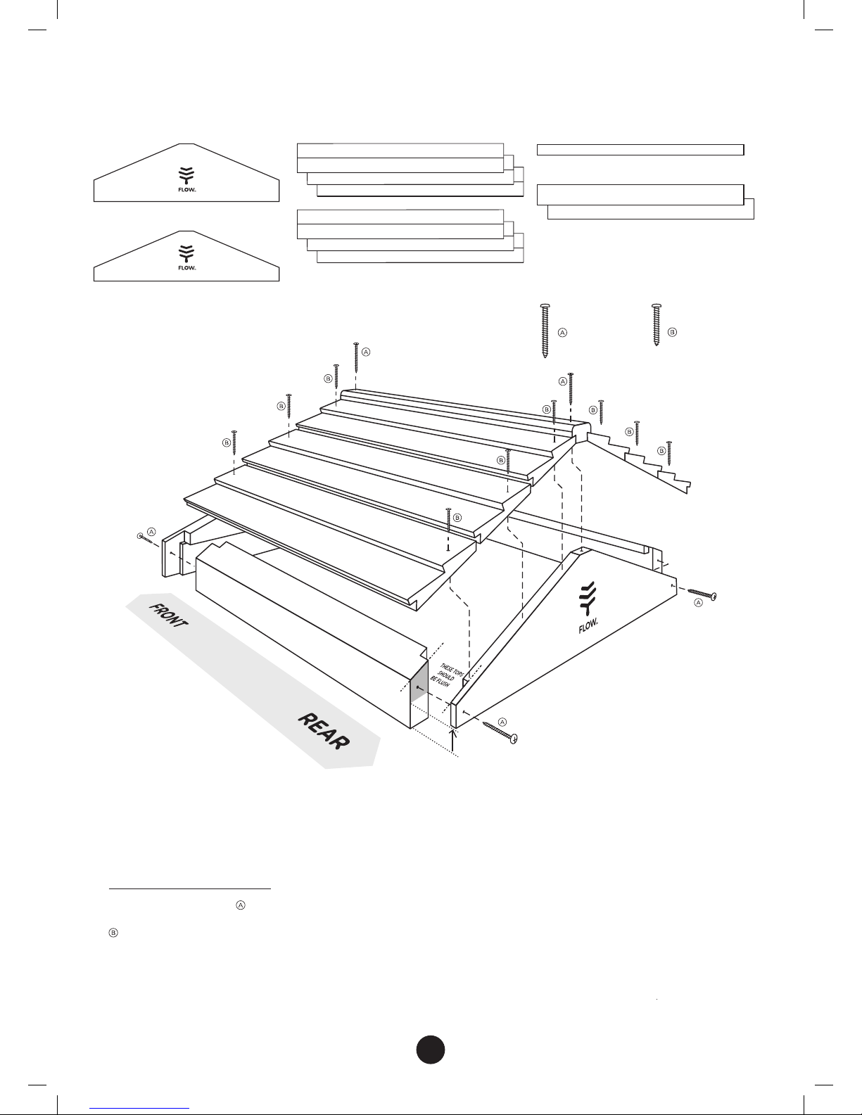
See illustration on right
1. Lay out all the pieces of your Flow® Hybrid Super.
2. Dry fit all the pieces together to make a box (as per the
illustration on right). Be sure they fit together tightly and
the handles are on the upper outside of the super.
3. If you are using clamps, clamp all the pieces together as
per the brood box construction to assist while inserting
screws. Screw the pieces together checking that the super
is square as you go along.
IMPORTANT NOTE: do not screw the rear window cover
in place as this piece will be used to gain access to the
Flow Frames.
4. To ax the metal bracing strip, turn the super upside
down. Put the rear window cover in place. To maintain
clearance, temporarily place some packing material, about
the width of a credit card, between the rear window cover
and the box side (see inset diagram).
The metal bracing strip sits across the notched ends.
Screw the metal strip in place (pre-drilling may avoid
splitting the wood).
You may wish to apply a suitable timber finish before
installing window and latches
5. Remove protective plastic from both sides of observation
window. Install into the rebate on the inside face of side
panel and screw into place.
6. Add the knobs to the rear and side observation window
covers and Flow Key access cover. Insert the springs into
the recesses on the latches before screwing them
to the super. The springs will prevent over-tightening of
the screws.
7. Insert wooden dowels into pre-drilled holes inside the
super. These will position your Flow Frames.
• 2 x side panels
(1 with observation window)
• 1 x front panel
• 1 x rear panel
• 1 x aluminium bracing strip
• 1 x Flow Key access cover
• 1 x rear window cover
• 1 x observation window
• 1 x window cover
• 1 x rear window latch
HARDWARE
2 x 20mm 6G
countersink
head screw
To ax metal
strip
4 x 10mm
6G
pan head
screws
To secure
window
2 x 32mm
wooden
dowels
For centering
Flow frames
4 x 23mm dia
wooden knobs
2 x observation
window latches
22 (+2 spare)
x 45mm 8G
pan head screws
To assemble box
sides and ends
3 x 25mm 6G
pan head screws
and springs
To secure
observation and
rear window
latches
4 x 20mm x
4mm
metal thread
screws
To secure
wooden knobs