1. INTRODUCTION
This manual is a part of machine and at the same time you
can consult to manual for using the machine safely and
efficiently during the entire duration of use. Therefore it should
be stored carefully in a safe place.
Users must read and apply the rules for safety and prevent
from possible accidents. The machine must be used by
competent people who read the manual carefully.
Using the machine with favorable conditions for safety of
people and environment is the responsibility of user.
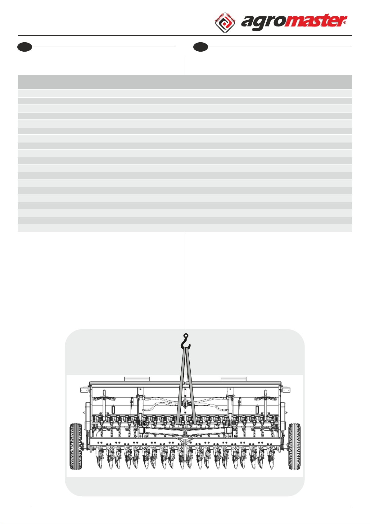
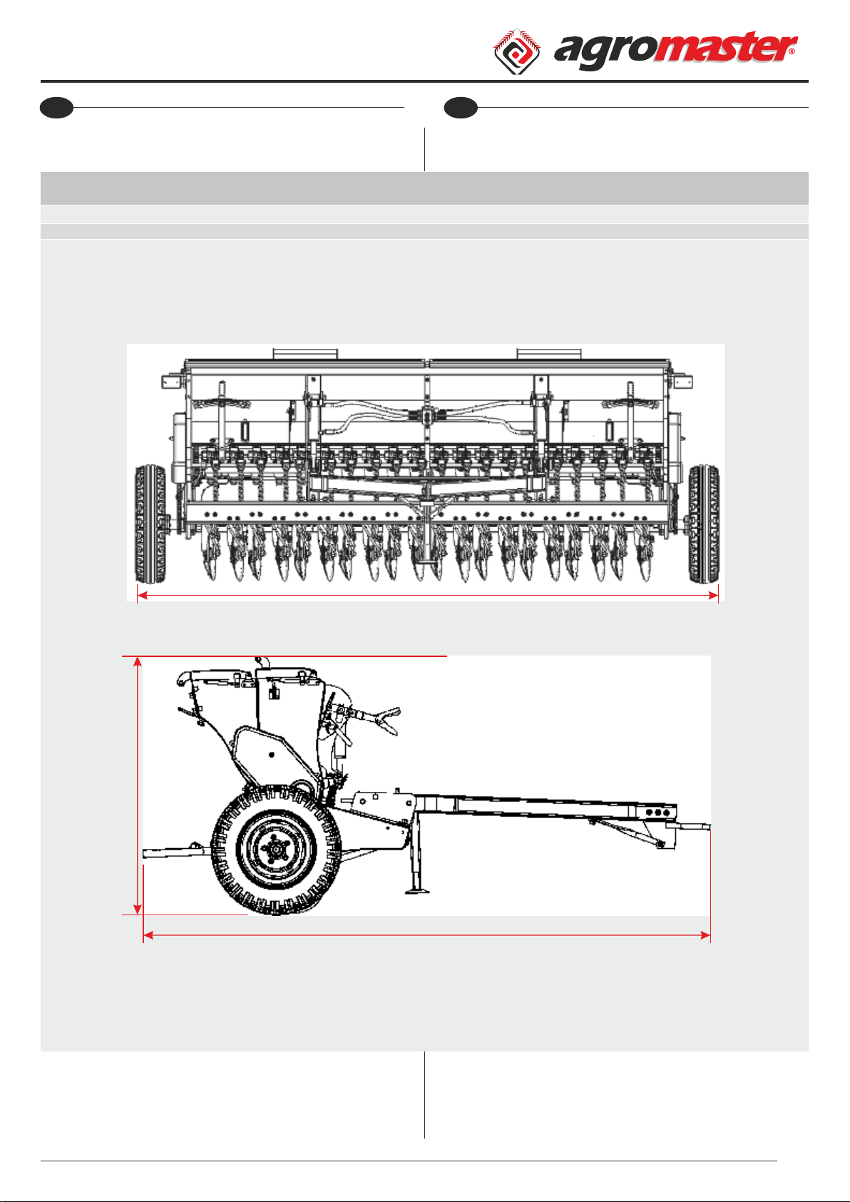
2. DESCRIPTION OF THE MACHINE
This trailed type machine is produced with 12-14-16-18-20-
22-24-26-28 rows. This machine isn't self moving so towed by
tractor by means of the machine's drawbar. It is also produced
with hydraulic lifting lever, universal three point linkage
system and hydraulic mounted type as optional.
Machine easily can be transported to the eld. This machine
is used for planting of wheat, barley, oat and rye seeds.
By means of the helical gear, required amount of seed and
fertilizer can be provided to planting feet through seed and
fertilizer pipes. Seed and fertilizer are left into soil by means of
the suffolk or disc coulters. Suffolk and disc coulters are lifted
and lowered by mechanic or hydraulic system which is the
equipped on the machine. Amount of seed and fertilizer
arranged by means of the chain which driven by wheel of
machine. Fertilizer hopper system is moved by left wheel and
seed hopper system is moved by right wheel of the machine.
2.1. AREAS OF USAGE
This machine must be used only for sowing of seed on the
cultivated eld.
4
ATTENTION
Do not ll the machine hoppers with
seed and fertilizer before transporting
of the machine to the eld. Hoppers
should be lled with seed and fertilizer
on the eld. Otherwise machine can be
damaged during transportation.
WARNING
Other usages which are not stated on
the manual not only can harm the
machine but also give cause for serious
damages for the user.
EN Operator's Manual
BM Kullanım Kılavuzu
TR
1. GİRİŞ
Bu ktap aynı zamanda maknenn br parçası olup, tüm
kullanım süres boyunca güvenl ve verml br kullanım çn
danışableceğnz ve blg ednebleceğnz br kaynak
ntelğndedr. Bu yüzden dama güvenl br yerde özenle
saklanmalıdır.
Kullanıcı ve müşter, kend güvenlğ çn belrtlen güvenlk
ve olası kazalardan korunma kurallarını dkkatlce okumalı ve
uygulamalıdır. Bu yüzden her koşulda makne, bu ktapta yer
alan teknk blgler kaza önlemlern tamamıyla ve dkkatlce
okuyan, yeterl blgye sahp uzman kşlerce kullanılmalıdır.
Unutulmamalıdır k maknenn nsan, çevre sağlığı güvenlğ
çn en uygun şartlarda kullanıldığının takp edlmes ve
kontrolü, kullanıcının sorumluluğundadır.
2. MAKİNE HAKKINDA TEMEL BİLGİLER
Bu makne, yalnızca 12-14-16-18-20-22-24-26-28 sıralı çeklr
tpte kend hareket gücü olmayan traktörün çek okuna
bağlanarak ekm yapablen maknedr. Ayrıca opsyonel olarak
hdrolk kaldırma üntes ve unversal 3 nokta askı sstem le
hdrolk asılır tpte de üretm yapılmaktadır. Bu nedenle ekm
yapılacak tarlaya nakl çok rahat yapılablmektedr.
Bu makne buğday, arpa, yulaf, çavdar gb tohumları ekmek
çn kullanılır. Tohum ve gübre gözüne dolan tohum ve
gübrenn stenlen oranda hels dşl makaralar sayesnde
kesntsz olarak tohum ve gübre boruları vasıtası le ekc
ayaklara sevk sağlanır. İk tpte üretm yapılan mekank ve
hdrolk slndr baskı yardımı le batma oranı ayarlanmış ekc
dsk ve balta ayak grubu sayesnde toprağa tohum ve gübre
bırakılır. Bırakılan tohum ve gübre mktarlarI hareketn her k
tekerlerden alan dşl zncr yardımıyla düzenler.
Gübrel maknelerde hareket sol tekerden alarak gübre
kovasını, sağ tekerden hareketn alarak tohum kovasını tahrk
eder.
2.1. KULLANIM ALANLARI
Ekm maknes sadece şlenmş tarlada tohum ekme ş çn
kullanılmalıdır.
DİKKAT
Makne le ekm yapılacak alana
g d e n e k a d a r t o h u m ve g ü b re
depolarını doldurmayınız. Ekm
yapılacak alanda gübre ve tohum
doldurunuz. Aks takdrde makneye
zarar vereblrsnz.
UYARI
Bu ktapta belrtlen kullanımların
dışında herhang br kullanım, makneye
zarar verebleceğ gb kullanıcı çn de
cddî tehlkelere sebep olablr.
3. GUARANTEE
• On delivery, check that the equipment has not been
damaged during transport and that the accessories are
integral and complete.
• The purchaser will enforce his rights on the guarantee only
when he has respected conditions concerning the benet of
guarantee.
• The guarantee is valid for one year, against all defects of
material from the date of delivery of the equipment.
• The guarantee does not include working and shipping
costs.
• Obviously, all damage to person or things are executed
from guarantee.
• The guarantee is limited to the repair or replacement of the
defective piece, according to the instructions of the
Manufacturer.
• Dealers or users may not claim any indemnity from the
Manufacturer for any damage they may suffer (because of
costs for labour, transport, defective workmanship, direct or
indirect accidents, lost of earnings on the working positions,
etc.)
3.1. EXPIRY OF GUARANTEE
Guarantee expires:
• If limits set out in technical data table are overshot.
• If instructions set out in this booklet have not been
carefully followed.
• If the equipment is used badly, defective maintenance or
other errors by client.
• If original spare parts are not used.
5
ATTENTION
• The customer should instruct
personnel on accident risks, on the
operator safety devices provided, on
noise emission risks and on general
accident prevention regulations
provided for by the international
directives and by the law in the country
in which the machines are used.
• In any case, the machine should be used exclusively by
skilled operators who will be held to follow scrupulously the
technical and accident - prevention instructions in this
manual.
• It is the user's responsibility to check whether the machine is
operated only in optimum conditions of safety for people,
animals and property.
EN Operator's Manual
BM Kullanım Kılavuzu
TR
3. GARANTİ
• Teslm aldığınızda maknenn taşıma sırasında hasar görüp
görmedğn, parçaların tam ve eksksz olduğunu kontrol
ednz.
• Alıcı, yalnızca garant kurallarına uyduğu takdrde
garantden yaralanablr.
• Malzemeden kaynaklanan arızalara karşı garant,
maknenn teslm tarhnden tbaren br yıl çn geçerldr.
• Garant, çalışma ve naklye ücretlern kapsamaz.
• İnsanlara ve eşyalara olan zararlar garant kapsamı
dışındadır.
• Garant, arızalanan parçanın üretcnn talmatları
doğrultusunda onarılması veya değştrlmes le sınırlıdır.
• Bayler veya kullanıcılar, (şçlk ve taşıma masraarı, kusurlu
şçlk, doğrudan veya dolaylı kazalar, çalışma esnasında kazanç
kaybetme gb) zararlardan dolayı üretcden herhang br
tazmnat talep edemezler.
3.1. GARANTİNİN BİTİŞİ
• Teknk tabloda gösterlen sınırlar aşılırsa;
• Bu kılavuzda belrtlen talmatlar dkkatlce takp
edlmezse;
• Hata kullanıcıdan kaynaklanırsa, makne yanlış kullanılırsa,
hatalı bakım yapılırsa;
• Orjnal parçalar kullanılmazsa, garant sona erer.
DİKKAT
• Müşter, kaza rskler, verlen operatör
güvenlk chazları, gürültü emsyon rsk
konusunda ve uluslararası drekter ve
maknenn kullanıldığı ülkenn
kanunları doğrultusunda düzenlenen
genel kaza önleme yönetmelkler le
lgl personel blglendrmeldr.
• Her durumda, makne, bu kılavuzdak teknk ve kaza önleme
talmatlarını dkkatl takp edecek yetenekl operatör
tarafından kullanılmalıdır.
• Maknenn nsan, hayvan ve mal güvenlğ çn en y
koşullarda çalıştırılıp çalıştırılmadığını kontrol etmek
kullanıcının sorumluluğundadır.