Adaptive BETAbrite Director Owner's manual

i
BETAbrite
Director
™
Programming Manual
For all
BetaBrite
Director signs
© 1998-2001 Adaptive Micro Systems
Form No. 9702-2002B
2/9/01
Assembly instructions
inside

ii
NOTE: Due to continuing product innovation, specifications in
this document are subject to change without notice.
Copyright © 1998-2001 Adaptive Micro Systems, Inc. All rights reserved.
The distinctive appearance of these products is a Trade Dress of Adaptive Micro Systems, Inc.
The following are trademarks of Adaptive Micro Systems: Adaptive, Alpha, AlphaNet plus,
AlphaEclipse, AlphaPremiere, AlphaTicker, AlphaVision, AlphaVision InfoTracker, Automode,
BetaBrite, BetaBrite Director, BetaBrite Messaging Software, Big Dot, PPD, Smart Alec, Solar,
TimeNet.
Visit us at our Internet World Wide Web site:

iii
Contents
Installation and setup .................................................................... 1
Description......................................................................................................1
Overview ..................................................................................................1
Technical specifications............................................................................2
EMI compliance .......................................................................................2
Assembling the Director..................................................................................3
Assembly parts ........................................................................................5
How to mount a Director on a wall...........................................................6
How to mount a Director on a stand ........................................................7
How to attach the brochure rack to a BetaBrite Director (optional)........11
Connecting signs to a computer....................................................................13
Sending messages to the Director.................................................................14
Basic sign operation.....................................................................15
Using the Remote Control .............................................................................15
Turning a sign on and off...............................................................................17
Setting a sign’s time and date........................................................................18
Clearing a sign’s memory..............................................................................20
Setting a sign’s password..............................................................................21
How to set a password...........................................................................21
What to do when you forget a sign’s password......................................23
How to delete a sign’s password............................................................23
Using the Remote Control’s sound control....................................................24
Setting a sign’s serial address .......................................................................24
Beginning text messaging ..............................................................26
Example 1 — Using upper and lowercase text..............................................26
Example 2 — Displaying messages in PAGE name order (A, B, C, etc.)........31
Example 3 — Displaying messages in time order .........................................33
Example 4 — Changing the text of an existing message...............................36
Example 5 — Deleting messages..................................................................39
Advanced text messaging ..............................................................40
Example 6 — Displaying the time and date...................................................40
Example 7 — Using the FLASH mode to highlight information.....................44
Example 8 — Using fonts and colors............................................................47
Example 9 — International characters ..........................................................52
Appendices ...............................................................................53
Appendix A — Sign diagnostic test...............................................................53
Appendix B — Updating the sign’s firmware (EPROM).................................54
Appendix C — Transferring a sign’s memory from one sign to another........55
Quick Reference Card ...................................................................56

iv
Warranty
Adaptive Micro Systems, Inc. warrants to the original purchaser that
the sign, keyboard and power supply will be free of defects in
workmanship and materials for a period of one year from the date of
purchase.
Adaptive Micro Systems, Inc. will without charge, repair or replace,
at its option, defective product or component parts upon delivery to the
factory service department accompanied by proof of the date of purchase
in the form of a sales receipt.
This warranty does not apply in the event of any misuse or abuse of
the product, or as a result of any unauthorized repairs or alterations. This
warranty does not apply if the serial number is altered, defaced or
removed from the sign. Incandescent lamps used in incandescent
products are not covered by this warranty.
The purchase price of this product does not include, from Adaptive
Micro Systems, Inc., any on-site support, service or maintenance.
Local ordinances prohibiting the use of flashing signs may exist in
some locations. Compliance with local ordinances is the sole
responsibility of the customer.
To obtain warranty coverage, this product must be registered. Please
complete the enclosed warranty registration card and mail it to Adaptive
Micro Systems, Inc.
How to obtain warranty service
1. Contact the distributor from whom the sign was purchased. If you do
not know where the product was purchased, contact Adaptive Micro
Systems Customer Service at 414-357-2020.
2. If the distributor cannot service the product, obtain a Return
Merchandise Authorization (RMA) number through that company.
An RMA number is required to obtain warranty service.
3. Fill out the Return Merchandise Authorization (RMA) Form on the
following page. To obtain warranty service, this form including the
RMA number must accompany the product.
4. Follow return instructions on the RMA form to return to Adaptive
Micro Systems, Inc.

v
Return Merchandise Authorization (RMA) Form
RMA Number: _________________________________
Date of Purchase: _________________________________
Company Name: _________________________________
Contact Person: _________________________________
Address: _________________________________
_________________________________
Phone Number: _________________________________
Fax Number: _________________________________
Description of Problem: _____________________________
_________________________________
_________________________________
_________________________________
_________________________________
Return Instructions
1. Obtain an RMA number from your distributor.
2. Fill out this form and include proof of purchase receipt if product is
under warranty.
3. Pack this form, the sign, keyboard and transformer in the original
carton (or a suitable replacement). Please write the RMA number on
the outside of the package. Any damage to the product during
shipment is the responsibility of the freight company or the owner of
the sign.
4. Ship the package,
postage/shipping prepaid
to:
Adaptive Micro Systems, Inc.
Attn: RMA No. ___________
7840 North 86th Street
Milwaukee, WI 53224
PLEASE WRITE THE RMA NUMBER ON THE LABEL OF THE SHIPPING BOX.
THANK YOU.

vi
BetaBrite Director User Manual
Installation and setup: Description 1
Installation and setup
The Director is an indoor LED sign that can display up to eight
16-character rows of text. The sign is capable of storing up to 26 “pages”,
or screens, of text information.
The sign can either be hung from a wall or mounted on a stand.
When mounted on a stand, an optional brochure rack can be placed
beneath the sign.
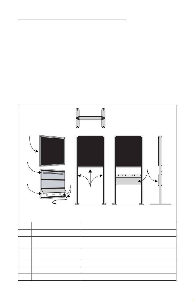
Description
Overview
Item Name Comments
A Director LED sign
B Mounting bracket This is a factory-installed option if the sign is to be wall-mounted.
(The mating bracket for the wall must be user-installed.)
C RS232/RS485 jacks The sign’s bottom panel tips up to expose the RS232/RS485 jacks
used to connect the sign to a computer. (See page 13.)
D Electrical socket and cable See “Technical specifications” below.
E Floor mount stand with crossbar This is a user-installed option if the sign is to be free-standing.
F Brochure rack This is an option.
Top view
Front and back
views, angled
(without stand)
Front view
(with stand) Front view
(with stand and
brochure rack)
Side view
(with stand and
brochure rack)
A
B
F
C
E
D

BetaBrite Director User Manual
2 Installation and setup: Description
Technical specifications
EMI compliance
This equipment has been tested and found to comply with the limits
for a Class A digital Device, pursuant to Part 15 of the FCC Rules. These
limits are designated to provide reasonable protection against harmful
interference when the equipment is operated in a commercial
environment. This equipment generates, uses and can radiate radio
frequency energy and, if not installed and used in accordance with the
instruction manual, may cause harmful interference to radio
communications. Operation of this equipment in a residential area is
likely to cause harmful interference in which case the user will be
required to correct the interference at his own expense.
Power 115/230 VAC, 150 W, 50/60 Hz
Dimensions
22.5L x 3.12D x 27H (57.2L x 7.9D x 68.6H cm) without brochure rack and stand
27L x 18D x 61H (68.6L x 45.7D x 154.9H cm) with brochure rack and stand
Weight
31.1 lbs. (14.1 kg) without brochure rack and stand
46.5 lbs. (21.1 kg) with brochure rack and stand

BetaBrite Director User Manual
Installation and setup: Assembling the Director 3
Assembling the Director
NOTE: Do NOT use the Director outdoors because water and dust
will damage the sign.
NOTE: Because of its size and weight, the Director should be
assembled by two people.
WARNING
Hazardous voltage.
Contact with high voltage may
cause death or serious injury.
Always disconnect power
to sign prior to servicing.
WARNING
Fasten sign to floor.
Otherwise sign may tip over
causing serious injury
or death.

BetaBrite Director User Manual
4 Installation and setup: Assembling the Director
Setting the RS232/RS485 jumper
Using the directions that follow, be sure the jumper in the Director is
set as needed:
To connect a sign to… set the jumper to…
one computer RS232
a sign network RS485
232
485
EPROM
2. Remove one screw from
each of the L-brackets
holding the sign’s cap.
3. Lift up and remove
the cap. 4. Pull up and remove the clear
plastic lens on the sign’s front.
5. To remove the jumper, grasp it
with needle-nosed pliers and
gently pull it out.
Place it on the 2 left posts for
RS232, as shown here.
Place it on the 2 right posts for
RS485.
1. Remove power from the sign.
6. Replace the plastic lens on the sign’s front, being careful not to catch any wires.
7. Replace the sign’s cap and L-brackets and then re-apply power to the sign.
BetaBrite Director User Manual
Installation and setup: Assembling the Director 5
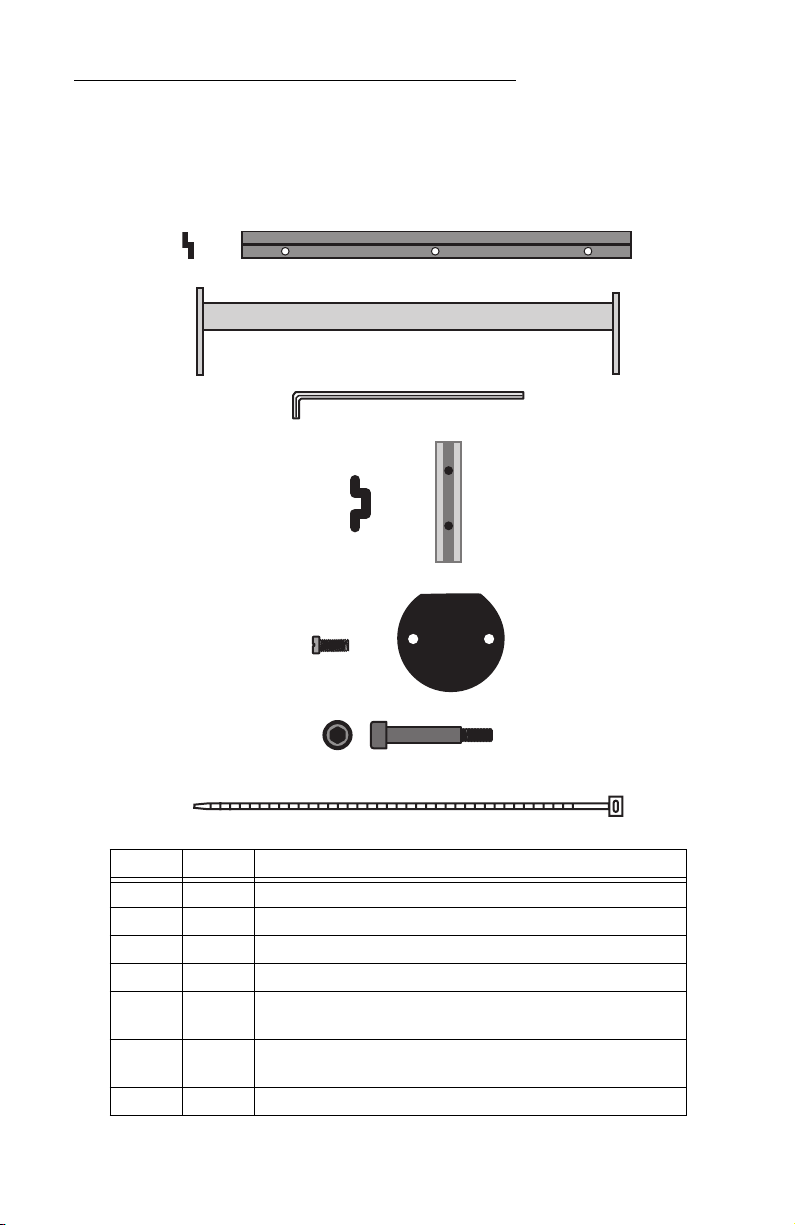
Assembly parts
These are in addition to the primary components shown on page 1.
These are not drawn to scale.
Part Quantity Component
A 1 Wall-mounting bracket, end view and face view
B 1 Crossbar
C 2 Hex (Allen) wrench: 1 smaller and 1 larger
D 2 Safety stop block, end view and face view
E4
2
3/8” long Phillips screw and
Post cap
F4
Shoulder bolt for optional brochure rack, end view and side view
(3/4” shoulder, 1-5/16” total length)
G 3 Tie wrap
A
B
C
E
G
D
F
BetaBrite Director User Manual
6 Installation and setup: Assembling the Director
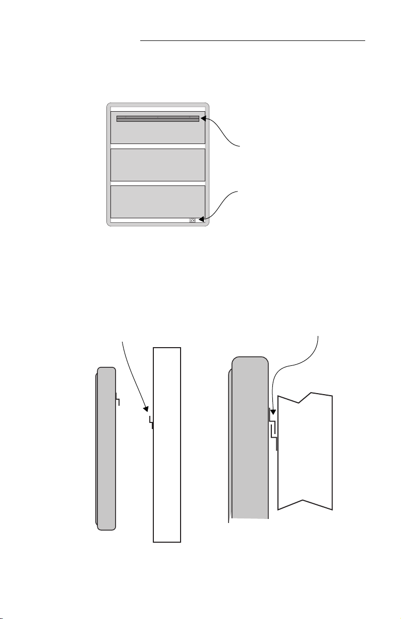
How to mount a Director on a wall
1. Make sure a mounting bracket is attached to the back of the sign:
2. Attach the wall-mounting bracket (supplied) to a wall. Then
hang the sign from this bracket.
NOTE: Only hang the Director from a wall capable of
supporting 116 pounds (52.5 kg). Use fasteners (not
supplied) also capable of supporting 116 pounds.
3. Plug the power cord into the sign and route it from the sign in
such a way that it is not in an area where people will be walking.
Mounting bracket,
factory-installed
Electric socket
Attach a wall mounting
bracket to a wall
To mount the sign, interlock
the two brackets.
BetaBrite Director User Manual
Installation and setup: Assembling the Director 7
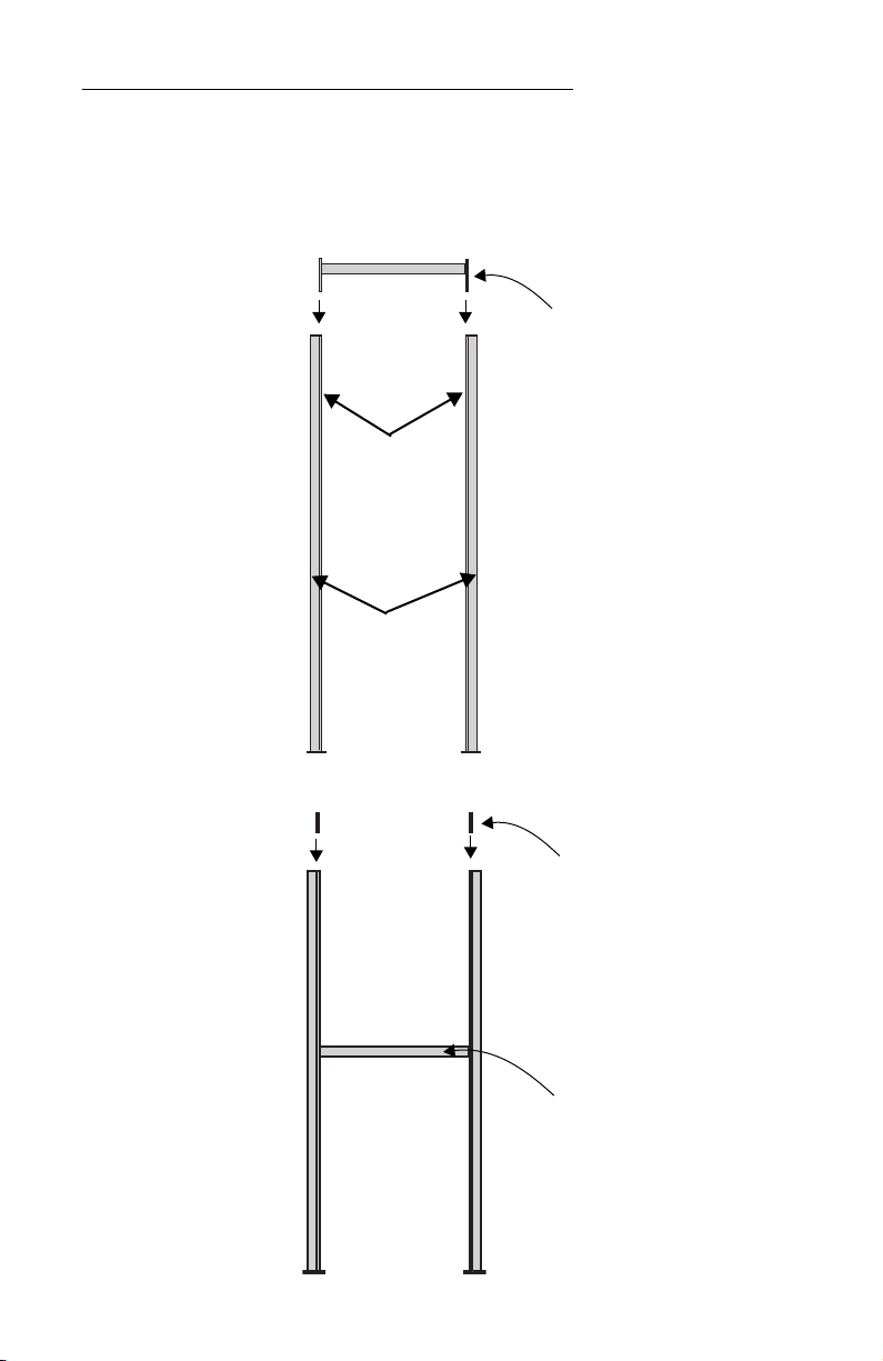
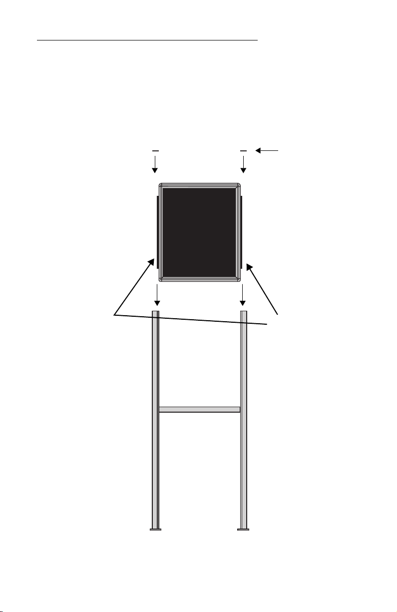
How to mount a Director on a stand
1. Lay the two mounting poles for the stand on a flat surface. Slide
the crossbar down the channels on the mounting poles.
2. Slide a safety stop down each channel:
Crossbar, long
ends pointed down
Channels
Mounting
poles
Crossbar
Safety stops

BetaBrite Director User Manual
8 Installation and setup: Assembling the Director
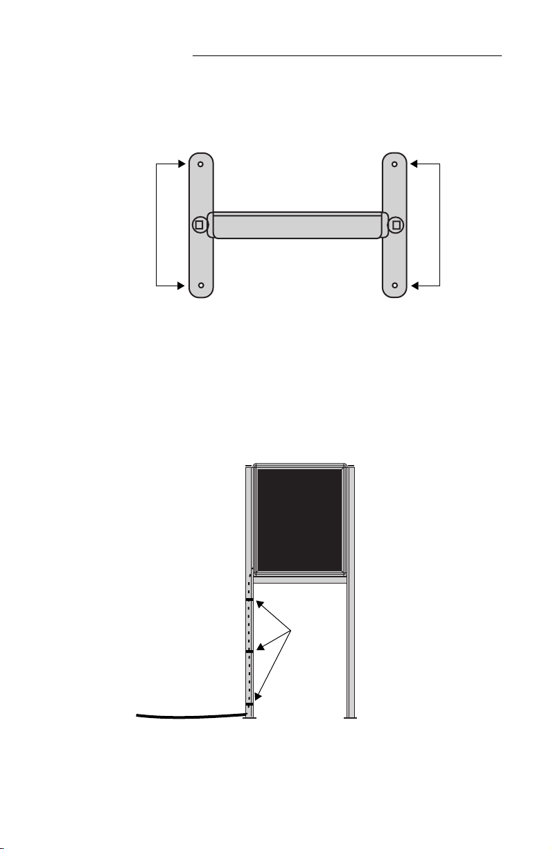
3. Use the smaller Allen/hex wrench to tighten the crossbar to each
mounting pole with the four pre-installed set screws. Then use
the same wrench to tighten each safety stop with its two set
screws, also pre-installed in each:
25.5
inches
(63.5 cm)
Fasten with two
screws on each side.
Fasten each safety
stop with two screws.
Crossbar
Safety stop
Mounting notch — line up the bottom
of the crossbar with this notch, a slight
indentation above the two screw-holes
for the brochure rack.
NOTE: Screws should be securely tightened.
(18 to 20-inch/pounds of torque recommended).
BetaBrite Director User Manual
Installation and setup: Assembling the Director 9
4. Place each of the sign’s mounting brackets in a channel on each
mounting pole. Then slide the sign down until it rests on the
safety stops. Finally, attach the post caps onto the tops of the
mounting poles using two of the 3/8” Phillips screws supplied
for each.
Post
caps
Mounting
brackets
BetaBrite Director User Manual
10 Installation and setup: Assembling the Director
5. Fasten the sign to the floor using four bolts or screws (not
supplied) in the locations shown below:
6. Plug the power cord into the back of the sign. Route the cord
from the sign in such a way that it is not in an area where people
will be walking.
Top view of sign
Completed assembly of sign
Shown without the optional brochure rack
Run the power cord along
one of the mounting poles.
Use the 3 supplied cable
ties to fasten the power cord
to the mounting pole. Cut
off excess cable tie length.
Fasten the power cord to the
floor in such a way (e.g.,
tape) as to prevent someone
from tripping over the cord.
Power cord
Cable ties

BetaBrite Director User Manual
Installation and setup: Assembling the Director 11
How to attach the brochure rack to a BetaBrite Director (optional)
1. Using the larger Allen/hex wrench, attach the four shoulder bolts
to the legs of the sign:
2. Slip the plastic brochure rack over the four shoulder bolts. Then
push the brochure rack down to secure it in place.
Attach two
shoulder bolts
on each leg.
BetaBrite Director User Manual
12 Installation and setup: Assembling the Director
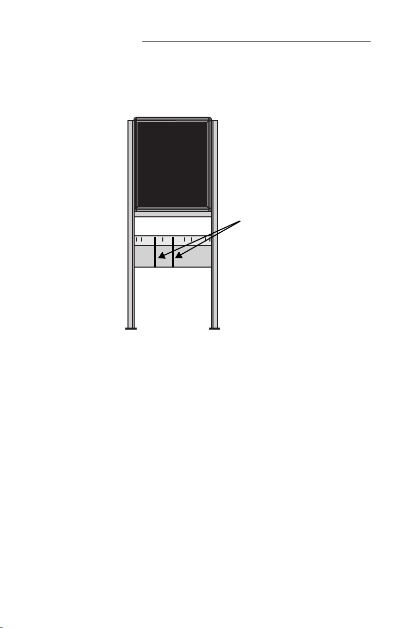
3. Use the supplied plastic dividers as needed in the brochure rack
to adjust for different sizes of literature.
Dividers
BetaBrite Director User Manual
Installation and setup: Connecting signs to a computer 13
Connecting signs to a computer
Connect the sign to a computer (as follows) in order to send messages
to the sign using that computer running Adaptive messaging software.
For a list of valid software, see “Sending messages to the Director” on
page 14.
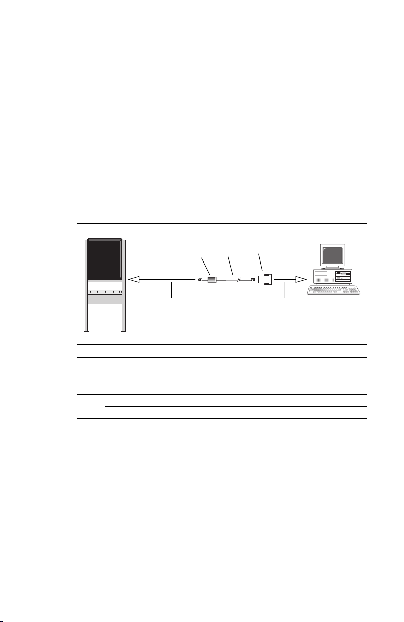
Connecting a single sign to a computer
1. Remove power from the sign.
2. Be sure the sign’s internal RS232/RS485 jumper is set to
RS232
.
(See “Setting the RS232/RS485 jumper” on page 4.)
3. Connect a personal computer to the sign as shown:
Connecting multiple signs into a network
For this type of networking, the sign’s internal RS232/RS485 jumper
must be set to
RS485
. (See “Setting the RS232/RS485 jumper” on page 4.)
Because there is such a wide variety of ways (e.g., LAN, wireless, etc.)
to connect networked signs, see the
Network Configurations
manual,
PN 9708-8046, for more information.
You may wish to assign a unique serial address to a sign. This allows
you to send messages to that particular sign when located on a network
with other signs. See “Setting a sign’s serial address” on page 24 for
details.
Item Part # Description
A
— Ferrite (ferrite end towards sign)
B
1088-8625
1
25-foot 6-conductor RS232 data cable
1088-8627 50-foot 6-conductor RS232 data cable
C
4370-0001C 25 pin sub-D/to 6 pos. RJ11 adapter
1088-9108
1
9 pin sub-D/to 6 pos. RJ11 adapter
1
This is included with the BetaBrite Messaging software kit.
ABC
To one of the
PC’s COM
(RS232) ports
To the sign’s RS232 jack
(under the back lower panel
of the sign)
PC running
messaging
software

BetaBrite Director User Manual
14 Installation and setup: Sending messages to the Director
Sending messages to the Director
Messages can be sent to the Director signs with either of two
methods.
One way is to use messaging software:
• BetaBrite Messaging Software
• Alpha Messaging Software
• AlphaNET
plus
• Smart Alec
• ActiveX
This user manual does not discuss usage of messaging software.
Please refer to the specific software manual for more information.
The other way messages can be sent to the Director signs is by using
the hand-held Remote Control. This method is discussed in “Beginning
text messaging” on page 26 and “Advanced text messaging” on page 40
of this manual.
Table of contents
Other Adaptive Monitor manuals


 manual")


