Adaptive FAST 275 User manual


1. Unpacking and Checking Carton Contents
2. Installation Location Selection
3. Hanging the Sign
4. Wiring
5. Turning On for the First Time
6. Fine Tuning / Aiming
7. Programming the Display
8. Readout Results
9. Advanced Features
10. Setting the Clock and Timer
11. Maintenance & Care
12. Technical Specifications
13. Options and Upgrades
14. Warranty
15. Trouble Shooting Tips
16. Contact Information
17. Data Recording Unit Instructions (Option)
Contents
Adaptive Micro Systems LLC | 7840 North 86th Street | Milwaukee, WI 53224
Phone (800) 558-7022 | AdaptiveDisplays.com
Thank you for the purchase of a FAST 275 Pole Mount Radar Speed Display Sign. This Manual
will guide through the minor assembly, mounting, programming and use. Please read and
understand this Manual and review the checklist in Section 1 below to be sure that you’ve
received everything you need prior to starting.
Take a moment to record the model and serial numbers below so that you have them in a safe
place for future use.
Fast-275 MODEL NUMBER SERIAL
NUMBER: DATE of
PURCHASE: OPTIONS
PURCHASED:
__________________________
__________________________
__________________________
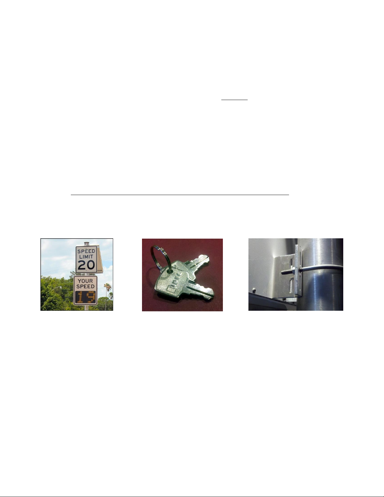
1. SHIPPING CHECKLIST
Item Qty Description
A
B
(1) FAST 275 Enclosed Sign w/internal radar
(2) Key for “On/Off” switch
C (-) Mounting hardware as specified on order
Figure 1a Figure 1b
Figure 1c
2. LOCATION SELECTION
In order to optimize your traffic calming results, there are a few simple things to keep in
mind and simple steps to follow. You’ll want a mounting location that’s on a relatively
flat stretch of road and is not too close to any stop signs, intersections, or sharp curves in
the road. A clear line-of-sight relatively free of obstructions such as large trees, fences or
other landscape features. The radar unit you’ve purchased is single-directional, so only
the speed of oncoming vehicles is displayed.
Adaptive Micro Systems LLC | 7840 North 86th Street | Milwaukee, WI 53224
Phone (800) 558-7022 | AdaptiveDisplays.com

3. HANGING THE SIGN
Your FAST 275 includes mounting hardware for a standard diameter streetlight pole.
Some basic mounting guidelines are shown in Figure 3a below. Please do not over
tighten mounting hardware at this step as you may wish to “fine tune” the exact angle of
your sign for optimum results as described in Section 6. If you have special mounting
needs and plan to modify the enclosure, please be careful to ensure that your hardware
does not contact interior components. Also be sure to use a sealant to maintain a
weatherproof environment inside the sign. Improper installation may cause damage to
interior components and void warranty.
4. WIRING
Your FAST 275 comes equipped to be powered either 12 volts D/C or 100-277 volts A/C
(50/60 Hz). The required voltage should be noted on the end of the power cord that leads
into the enclosure. If you are unsure what you’ve purchased, please contact us before
proceeding. Enlist the services of a licensed electrical contractor for installation assistance
if needed.
For A/C powered units the power cord exiting the back of the enclosure has
three wires; a WHITE = Neutral lead, BLACK = Line (Hot), and GREEN = Ground.
Please be cautious and take care to observe polarity of wires while installing. If
optional Data Recording System is purchased, an additional wire is included –
WHITE = Data positive, BLACK = Data Negative, GREEN = Data.
For D/C powered units WHITE = Positive, BLACK = Negative, and GREEN = Data
(for the optional data collection unit).
5. POWER UP
Now that your enclosure is pole-mounted securely and your wiring is completed; you are
ready to power up. Find the included key, insert into the switch at the bottom, right side
of the enclosure. Turn clockwise ¼ turn to the “ON” position. Your display should light
up, cycle through some numbers as it takes readings of the ambient light at your
location, and read “NM” for Normal Mode. It will then begin to cycle through the setup,
please read Section 7 entitled “PROGRAMMING YOUR SIGN” for more information.
6. FINAL POSITIONING / FINE TUNING
See figures 1a and 1c for some basic positioning tips. Keep in mind that the 12” tall
characters are readable to 750 feet. If the radar unit is picking up vehicles too far away,
simply rotate the unit clockwise so that it’s facing the opposite curb a bit more. Likewise,
if the unit is picking vehicles up too close or not far away enough, rotate counter-
clockwise. Practice with as many vehicles as necessary until desired results are achieved.
Remember, you may adjust the radar gun angle (aim) in the FAST 275 as well as the
mounting angle of the enclosure on the pole for maximum fine-tuning. See figures 3a
and 3b.
Adaptive Micro Systems LLC | 7840 North 86th Street | Milwaukee, WI 53224
Phone (800) 558-7022 | AdaptiveDisplays.com
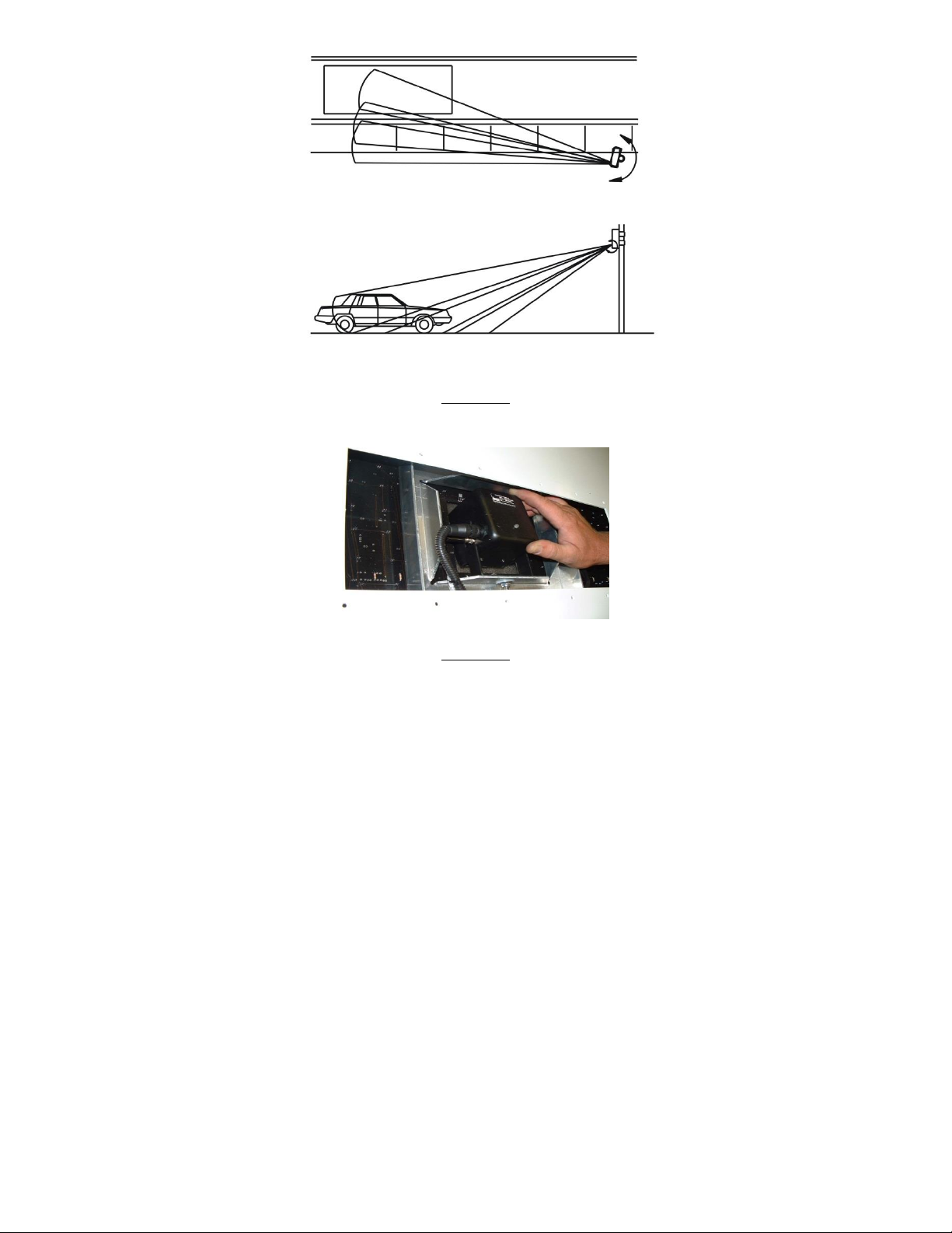
Figure 3a
Dialing in Approach Angle Sensitivity
Figure 3b
Internal Radar Gun swivels vertically
for diverse aiming options
7. PROGRAMMING THE DISPLAY
Now that your enclosure is pole-mounted securely, the “YOUR SPEED” sign is affixed,
and your wiring is completed, you are ready to power up. Find the included key,
insert into the switch at the bottom, right side of the enclosure. Turn clockwise ¼
turn to the “ON” position.
When first turned on, the display will show a number between zero and 9. This
number indicates the brightness level of the display indicating the brightness is
being set automatically due to the surrounding sun light. Note: The brightness
control is always on automatic but it can be checked for proper operation by the
user, if needed. To check this, refer to the paragraph “Auto Intensity Diagnostic
Mode, code 9981” in the Advanced Features Section.
You will see there is a small programming push button located underneath the
display at one bottom corner (blue arrow Figure 4a). This button or the remote will
set all display features.
Adaptive Micro Systems LLC | 7840 North 86th Street | Milwaukee, WI 53224
Phone (800) 558-7022 | AdaptiveDisplays.com

Figure 4
Underside of Enclosure
Key Chain Remote Control
The left button directs the numbers up with the other directing down. When the sign is in
run mode, holding both buttons in for 1 second resets the sign without having to cycle
the power key.
To replace its battery, remove the small Phillips head screw located on the lower back and
replace with a type 27A, 12volt alkaline cell.
The speed codes and their meanings
Read over the following programming codes listed in the Speed Code Table
below to become familiar with the two-letter groups (modes) you want to set in
the sign using the push button. Concentrate on the “Normal Mode” (NM) and
“Violator Alerts”
(VA) modes only, for now. Notice that they are grouped so that for example, when
“VA” is selected, you can set the “Minimum Speed”, Flash (speed), Blank (speed),
etc. As the last numbers are entered, the display is ready and goes blank.
SPEED CODE TABLE
Two-letter Mode Meaning Description
NM => “Normal Mode” Sign shows all speeds normally
with no speed filtering
VA => “Violator Alert”
MS => “Minimum. Speed”
SL => “Slow”
RB => “Red & Blue”
FL => “Flash”
BL => “Blank”
“Violator Alert” MENU
Min. speed for sign to display
Speed at which red “SLOW”
shows (Optional Feature)
Flashing “Red & Blue” speed
(Optional Feature)
Speed at which to flash
readout Speed at which to
blank screen
Adaptive Micro Systems LLC | 7840 North 86th Street | Milwaukee, WI 53224
Phone (800) 558-7022 | AdaptiveDisplays.com

**ND => “No Display” Unit collects radar data with no display
** OPTIONAL ONLY for units with the optional data collection
software feature.
Feature must be enabled - See Advanced Features Mode Section.
SETTING THE SIGN IN “NORMAL MODE”
The simplest mode to put the sign into is the “NM” (Normal
Mode). Instructions:
1. Turn the power on with the key. After the brightness number changes,
start pushing the button and stop on the two letter code “NM”.
2. As the display goes dark, it is now running in “Normal Mode”. In other
words, the sign will display the speed of oncoming vehicles from 5 mph
(down to 1 mph is also available, see Advance Features Section) to 99
MPH without showing any alerts. So for this code only, no further
programming would be needed.
PROGRAMMING THE SIGN IN “VIOLATOR ALERT” MODE
This section covers setting the standard “Violator Alert” functions including the
optional “Slow”, “Red & Blue” flashing signals. Note: The pushbutton instructions
described in the following paragraphs also apply to the use of the key chain
remote control buttons.
Turn power on. After the brightness number changes, push the button and stop
on
“VA”. The display is now in “Violator Alert” setup mode. The Violator Alerts 1 to 5
will then begin to appear in the order of the photos as shown below. Note: If the
Timer is enabled, (see Section 11 “Setting the Clock and Timed Events) the sign
will run in Violator Mode (or any other mode) only during the selected event
timed program. Otherwise, if the timer is disabled, the sign will run continuously
(not recommended for overly long periods of time when on battery power only).
“Violator Alert”
Violator Alert 1: MS - Minimum Speed
After seeing the “VA” screen, the display will show “MS” (see photo below) along
with a number. The number represents the lowest speed at which the display will
Adaptive Micro Systems LLC | 7840 North 86th Street | Milwaukee, WI 53224
Phone (800) 558-7022 | AdaptiveDisplays.com

start showing all oncoming vehicles. When this number appears, the operator has 5
seconds within to start pushing the button in order to program this “MS” speed
setting. Press the button until the desired speed setting is reached. (Note: If the
button is held down, the numbers will increment fast without having to press the
button many times. The numbers will start over after 99 if you miss your desired
speed without turning off the power. If using the key chain remote, simply press
either button to move the numbers forward or backward). Once the desired setting is
reached, stop and wait for the next screen to appear after approximately 5 seconds.
The screen will then change to the next screen for speed setting.
“Minimum Speed”
Violator Alert 2: SL - SLOW (Optional Feature)**
Check your packing slip or order to verify that this optional feature has been
included with your product. If this feature was ordered, the display will now show
the red “SL” (Slow) message and show a speed setting number. The red “Slow”
message is effective in helping to calm traffic. When the operator sees the setting
number appear, push the button within 5 seconds in order to change this number
until the desired speed setting is reached. Note: You can set the numbers even
when the words “Slow” are flashing. Once the desired setting is reached, stop
pressing the button and wait for the next screen, after approximately 5 seconds.
Violator Alert 3: RB - Red and Blue flashing lights (Optional Feature)**
Check your packing slip or order to verify that this optional feature has been
included with your product. If this feature was ordered, the display will now show
“RB” which effectively flashes the Red and Blue flashing light pattern at the driver
while displaying their speed. The operator has 5 seconds to start pushing the
button in order to change the number setting. Note: You can set the numbers
even when the “Red & Blues” are flashing. Press the button until the desired
speed setting is reached. Once the desired setting is reached, stop and wait for
the next screen after approximately 5 seconds.
Adaptive Micro Systems LLC | 7840 North 86th Street | Milwaukee, WI 53224
Phone (800) 558-7022 | AdaptiveDisplays.com
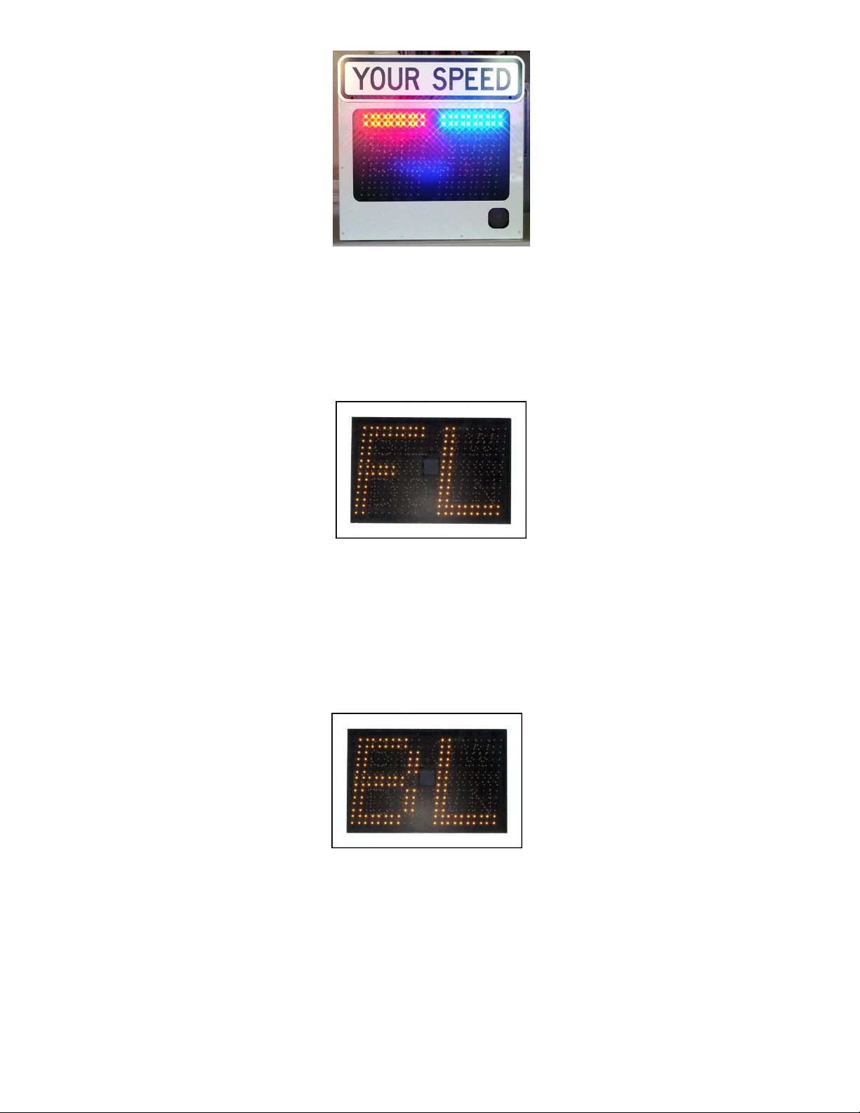
Violator Alert 4: FL - Flashing Speed
The display will now show “FL”. When drivers go over this setting, they will see
their over-the-limit speed flash. The operator has 5 seconds to start pushing the
button in order to change the speed setting. Press the button until the desired
speed setting is reached. Once reached, stop and wait for the next screen to
appear after approximately 5 seconds.
“Flashing Speed”
Violator Alert 5: BL - Blanking Speed
The display will show “BL” which is the speed limit that the display will no longer
show the oncoming vehicles speed. This setting will prevent drivers from
increasing their speed over this speed limit to see how fast they can go. Press the
button until the desired speed setting is reached. Wait approximately 5 seconds
and the sign will go dark. The display is now in service and operating in “Violator
Alerts” mode.
“Blanking Speed”
** Optional SLOW and Flashing Red & Blue Violator Alerts can be purchased and
activated at any time. Call Customer Service 866-982-2107 for pricing and
information.
Notes: After this last “BL” screen, all of the violator alert settings have been saved even
after the sign is switched off. When the sign is turned on again, it will run thru all of
the modes and their speed settings for the operator to review.
Adaptive Micro Systems LLC | 7840 North 86th Street | Milwaukee, WI 53224
Phone (800) 558-7022 | AdaptiveDisplays.com

If changes are needed, press the sign mounted button for 5 seconds which will
start the mode settings to display again. If using the key chain remote, hold
the left button in for 1 second for the same effect.
If desired, the sign can be pre-set at your base facility for transportation and
set-up at a different location.
The violator alerts can be set in any order, but not at the same speed. If
attempted, this setting will skip to the next available number. To get the best
effect from the alerts, set the speeds at least 3-4 MPH difference. If you wish to
not use one of the violator alert settings, set the speed high, i.e. 97 MPH.
Holding the button will scroll through the numbers faster for quicker setup. If
the desired setting is passed, the numbers will start over after 99.
If using the optional key chain remote, the left button advances the numbers
while the right button reverses them.
To start over, either turn off/on the sign with the power key OR when using the
key chain remote, hold the left button in for 3 seconds for a power reset.
After setting the clock, (see Section 11 “Setting the Clock & Timed Events”) the
sign will revert back to Normal Mode (NM). If Violator Alert mode is desired, it
will have to be set to “VA” mode again.
Violator Alert Settings Summary
Push button until display shows “VA”
Wait five seconds for MS (Minimum Speed) to display
“MS” will display. Push the button to set the desired speed.
Wait five seconds for SL (SLOW) to display
“SL” is displayed. Push the button to set desired speed.
Wait five seconds for RB (Flashing Red & Blue) to display
“RB” is displayed. Push the button to set desired speed.
Wait five seconds for FL (Flashing Speed) to display
“FL” is displayed. Push the button to set desired speed.
Wait five seconds for BL (Blanking Speed) to display
“BL” is displayed. Push the button to set desired speed.
After five seconds the last speed sets and the display goes dark
Traffic Set-Up Examples
35 mph neighborhood speed limit
Set the “MS” (the radar detected Minimum Speed limit) at 5 mph, the
“SLOW” message at 35, “Flashing Speed” at 40mph, the “Red & Blues” at 50 and
the Blanking Speed at 60. This is what will happen: Oncoming vehicles speeds
will be shown on the sign traveling from 5 to 34 MPH. If the vehicle is traveling
35 to 39, the SLOW message will flash. Between 41 and 49, their speed will be
displayed while flashing. Over 50MPH, the display will show the Red & Blue
flashing lights pattern. At 60 and above, the display is blank. As the vehicle slows,
the appropriate “Violator Alert” will show for their speed until they reach 34 MPH
where their speed is displayed normally.
Adaptive Micro Systems LLC | 7840 North 86th Street | Milwaukee, WI 53224
Phone (800) 558-7022 | AdaptiveDisplays.com

School Zones
Set the “MS” (the radar detected Minimum Speed limit) at 15 mph (so
drivers in a school zone obeying the speed limit are not distracted), the
“Flashing Speed” at 16mph and the “Blanking Speed” for 40mph. This is
what will happen: For speeds under 15 MPH, no speed will be displayed.
The display will flash the speed for vehicles traveling between 16 and 39
MPH. No speed will be displayed above 40 MPH.
8. RESULTS
The readings from the radar unit are filtered. The radar unit is very sensitive, so for
continuity of the oncoming driver, not every reading may be displayed. If there is a
difference between vehicle speeds of more than 3 miles per hour per second (extreme
acceleration or deceleration), the display will simply hold the last recorded speed for a
few seconds rather than jumping back and forth between speeds. A couple of examples:
Example 1:
Example 2:
If a vehicle is traveling at 35mph and the car behind him is traveling
at 40mph, the sign will display the first vehicle at 35 until it passes.
The first vehicle’s speed will show for 1-1/2 seconds after it passes, so
the radar can establish and display vehicle two’s speed at 40mph.
If a vehicle accelerates towards the sign from a stop at greater than 3
miles per hour per second, no speed will be displayed. If a vehicle
accelerates at 3 miles per hour per second or less, the sign will
display the speed as it increases.
9. ADVANCED FEATURES
In addition to the standard features there are some advanced features available mainly
for trouble shooting.
To enter the Advanced Feature mode, turn the unit ON and press the programming
button five (5) times before the intensity number blinks. First an “A” will appear on the
left digit and a number on the right. Press the programming button until the
appropriate number is shown for that slot. Wait for a “B” to appear and repeat this for “C”
and “D” as well. This will put you into that mode until the unit is turned off and back on
again. See below a list of codes and slots for these advanced features.
A B C D
9 9 6 9
9 9 7 1
9 9 7 3
9 9 7 5
9 9 7 9
9 9 8 1
9 9 8 3
9 9 8 7
9 9 8 9
Minimum Speed Mode
Alternate Slow Down Mode
Demo mode (see further instructions)
Show Serial Number
Display Diagnostic Mode
Auto Intensity Diagnostic Mode
Turn On & Off Radar Acceleration Filter
Turn On & Off No Display Availability
Turn On & Off Set Time Availability
Adaptive Micro Systems LLC | 7840 North 86th Street | Milwaukee, WI 53224
Phone (800) 558-7022 | AdaptiveDisplays.com

Minimum Speed Mode
Lower speeds of 5 mph are distracting in most applications but are desirable in some. As
a default, the display will only show down to 5 mph but down to 1 mph is available.
Putting in the minimum speed code will turn on and off the down to one mode. If after
putting in the minimum speed code, the display shows “S1” then the speed will show
down to 1 mph. If “S5” shows then the speed will only show down to 5 mph.
Alternate Slow Down Mode
The display can show the “Slow Down” violator alert two ways. One is that only “Slow
Down” is shown if the vehicle speed is over that set speed. The other is that the “Slow
Down” will show and then the vehicle speed will display, alternating between the two
until the vehicle slows below the set speed. Both are very effective but one could be
preferred above the other. The default is just “Slow Down”. To switch from one or the
other, put in the code and if the display shows “On” then only the “Slow Down” message
will display. If after the code is put in and “Off” shows then the display will alternate
between “Slow Down” and their speed.
Demo Mode
Demo Mode will allow you to select 1 of 6 Demo. The display will show DM for Demo
Mode and then a number. Change the number to the desired demo
1 = Counts up and down from 51 to 59 and flashes
Demonstrates Dimming Feature
Shows “Slow Down” Violator Alert
Shows “Red and Blue” Violator Alert
2 = Shows just “Slow Down” Violator Alert
3 = Shows just “Red & Blue” Violator Alert
4 = Counts up and down from 31 to 39 flashes
Demonstrates Dimming Feature
Shows “Slow Down” Violator Alert
Shows “Red and Blue” Violator Alert
5 = Scrolls RU2 Fast
6 = Snow Flakes
EX = Exit back to main menu
If the button is pressed during the Demo, the display will allow you to re-select another demo.
Show Serial Number Mode
Serial Number mode will display seven (7) two (2) digit numbers. This is your software serial number
Display Diagnostic Mode
Display diagnostic mode will make several patterns on the display used to test the display integrity.
Pressing the program button five (5) times while the display is blank just after The red and blue test
will exit and return to Main Menu.
Auto Intensity Diagnostic Mode
Auto Intensity Diagnostic Mode will test the ability to auto adjust the brightness of the display
according to the ambient light. A small sensor in the center of the sign reads the outside light so the
processor may determine how bright to make the display. Once in this mode, the outside light can
be varied and will show a number from 0 to 9, with 0 being the lowest and 9 the highest. Putting
your hand over the sensor can change this reading.
Adaptive Micro Systems LLC | 7840 North 86th Street | Milwaukee, WI 53224
Phone (800) 558-7022 | AdaptiveDisplays.com

Turning the Radar Acceleration Filter On and Off
Once this code is put in the display will show either an “On” or “Off”. “On” means the filter
was off and will now be turned on. “Off” means the filter was on and will now be turned off.
We recommend the Filter be “On” for most applications.
Turning the No Display Availability On and Off
This feature simply leaves the “ND” mode in or out of the main menu. “On” means the
display availability was off and will now be turned on. “Off” means the Display Availability
was on and will now be turned off. We recommend the Display Availability be “Off” for most
applications.
Turning the Set Time Availability On and Off
This feature simply leaves the Set Time mode in or out of the main menu. “On” means the
Set Time Availability was off and will now be turned on. “Off” means the Set time
Availability was on and will now be turned off. We recommend the Set Time Availability be
“Off” for most applications.
“Optional” Slow Down and Red Blue Violator Features
These features are built in to your radar display but may not be configured to operate
because they are either not appropriate for the application or were not purchased.
These optional Violator Alerts may be viewed by running the demo mode in the “Advanced
Features” section of this manual.
10. SETTING THE CLOCK AND TIMED EVENTS
Note: Unless the sign is to be powered on and off automatically at certain times, it is not
necessary to set the clock
The internal timer is a 24 clock used to turn off the display’s system to extend battery life or
to prevent disturbing residents at late or early hours. This feature will not take into account
weekends, holiday or daylight savings time. The Set Time function must first be “turned on”
in order to set the On/Off times. See Section 10 – Advanced Features, code 9989 to activate
this function. Once the feature is activated, you will see the following codes added to the
startup display setting:
TIMER CODE CHART
ST => “Set Time”
EN => “Enable”
DS => “Disable”
ON
OH =>
OM =>
“On Hour”
“On Minute”
OFF
FH =>
FM =>
“Off Hour”
“Off Minute”
TIME
HR => “Hour”
MN => “Minutes”
Time Set Menu
Turn on the timer feature
Turn off the timer feature
Hour at which sign is to turn on
Minute at which sign is to turn
Hour at which sign is to turn off
Minute at which sign is to turn
Set current time hour (24 hour)
Set current time minute
Adaptive Micro Systems LLC | 7840 North 86th Street | Milwaukee, WI 53224
Phone (800) 558-7022 | AdaptiveDisplays.com

SETTING THE EVENT TIMER
Note: If you become lost while setting any of the numbers, the settings operate the
same as the display set. In other words, if any numbers are missed the first time around,
they will repeat again by holding in the pushbutton. Also, the power key can be cycled
on and off to start over from the beginning or the key chain remote option allows you
to advance or reverse all numbers using both of its buttons.
As an example, let’s set the sign to operate only during normal to high traffic hours (for
conserving the battery) to run daily from 5:30 AM to 11:45 PM. The current time is 8:17
AM. These would be the programming steps:
Turn power on. After the brightness number changes, push the button and stop on
“ST”, the “Set Time” mode. Push the button until the display shows “EN” (Enable):
Wait five seconds for “OH” (“ON” Hour) to display.
“OH” displays. Push the button to see 05 (hours) on the display
Wait five seconds for “OM” (“ON” Minute) to display.
“OM” is displayed. Push the button to see 30(minutes)
Wait five seconds for “FH” (“OFF” Hour) to display.
“FH” is displayed. Push the button to see “23” (11PM)
Wait five seconds for “FM” (“OFF” Minute) to display.
“FM” is displayed. Push the button to see “45” desired speed
Wait five seconds for “HR” (Current Hour) to display “HR”
is displayed. Push the button to set “08”
Wait five seconds for “MN” (Current Minute) to display
“MN” is displayed. Push the button to set “17”
11. MAINTENANCE, CLEANING, & CARE
Sign Enclosure:
Your display has been powder coated for a long-lasting great look. While powder coat
finishes are tougher and much more flexible than conventional solvent based paints,
they are about the same hardness as automotive paint, so they will scratch. To clean a
powder coated surface, use the same care and methods you would use to clean your
car. Gently wash with a clean, soft cloth and a mild detergent followed by a clear water
rinse. Even though most powder coatings are highly resistant, certain solvents can
harm them. Avoid contact with nail polish remover, paint or lacquer thinner, motor
oils, transmission and brake fluids or parts cleaning fluids. If any of these should
contact the powder coated surface, immediately wipe the area with a soft, clean cloth,
and wash as described above.
Adaptive Micro Systems LLC | 7840 North 86th Street | Milwaukee, WI 53224
Phone (800) 558-7022 | AdaptiveDisplays.com

Lexan Screen and Solar Panel (if purchased):
To prevent scratching, please take care to use only the proper cleaning
products and techniques outlined here;
1. Rinse with lukewarm water. Wash gently with mild soap or detergent and lukewarm
water, using a soft cloth or sponge. DO NOT SCRUB or use brushes or squeegees.
2. Rinse again. Dry with soft cloth or moist cellulose sponge to prevent water spotting.
3. To remove wet paint, glazing compound or grease, rub lightly with a good grade of
VM&P naphtha or isopropyl alcohol, then wash and rinse. DO NOT USE GASOLINE.
4. Compatible Cleaning Agents include Fantastik, Formula 409, Hexcel, F.O. 554, Joy,
Lysol, Mr. Clean, Neleco-Placer, PineSol, Top Job, & Windex.
12. SPECIFICATIONS
a. Overall:
Dimensions:
Shipping Weight:
Operational Temperature
Range: Speed detection range:
26” Wide x 32.5” Tall x 4” Deep
40 Lbs.
-22 degrees F to +158 degrees F
1-99 mph
b. Casework:
Aluminum construction, rear panel access to critical components.
Lexan® display shielding with a smoked, non-glare finish for easy
readability even in direct sunlight.
Universal mounting bracket included.
c. Electronics:
K-band, single-directional (approach only) radar gun.
Latest generation AlInGaP, high intensity LED’s.
12” Full Matrix (rounded) characters for quick recognition.
Minimum Speed Display, High Speed Blanking & Flashing Digital
Violator Alert – Standard.
Automatic intensity adjustment to ambient light conditions.
12 VDC operation, 12 VDC or 100-277VAC, 50/60 Hz input.
Keyed On/Off switch.
Single cycle ON/OFF clock – standard
Automatically defaults to last settings upon power up.
13. OPTIONS and UPGRADES
-Powder coat paint inside and out in a variety of colors
-RU2 Traffic Count Data Acquisition System with software
-Solar Energy Package w/Panel, charger, and mounting
bracket
-“SLOW” violator alert
-Red-Blue flashing bars violator alert
Adaptive Micro Systems LLC | 7840 North 86th Street | Milwaukee, WI 53224
Phone (800) 558-7022 | AdaptiveDisplays.com

14. WARRANTY
Adaptive warrants parts and workmanship on the LED display for (5) years. The radar unit is
warranted by the manufacturer for (2) years. On-site labor is not included. Parts are repaired
within five business days of receipt, and include ground shipping. Warranty does not include
physical damage from misuse, acts of nature, terrorism or vandalism. Wear and tear items such
as tires are not covered. Please forward any warranty issues to the Shipping Address found in
Section 16. Please call for authorized RMA before returning any parts.
15. TROUBLE SHOOTING TIPS
a. If no speed is displayed:
i. Check battery(s) with a voltage meter to be sure they are outputting at least 12
volts.
ii. Check battery charger indicator lights. Be sure there is power to the charger from
your outlet and power out from the charger measures higher than 12 volts.
iii. Check your “Set Time” feature and be sure your clock is set properly to display at
the correct times. If in doubt, disable the set time feature.
b. If a “NR” is displayed:
Please note the radar can be accessed via a panel on the back side of the LED display.
Use the “L” key to remove the tamper resistant screws and slide the cover over.
i. Check the radar gun connector to be sure of a good connection.
ii. Check the indicator light on the back of the radar unit:
A solid red LED indicates a vehicle traveling away from the unit is
being measured.
A solid Green LED indicates a vehicle traveling towards the unit is
being measured.
A flashing red LED indicates power but no target is being
acquired.
3. If display is not showing the proper oncoming vehicles – See section 5.
4. If you loose keys:
iii. The On/Off key and enclosure “triangle” key can be purchased. Please
call for pricing.
Note: In a pinch, the “triangle” lock may be opened by placing a flat
head screw driver into the grove and gently turning counter clockwise.
Adaptive Micro Systems LLC | 7840 North 86th Street | Milwaukee, WI 53224
Phone (800) 558-7022 | AdaptiveDisplays.com

Adaptive Micro Systems LLC | 7840 North 86th Street | Milwaukee, WI 53224
Phone (800) 558-7022 | AdaptiveDisplays.com
16.ADAPTIVE CONTACT INFORMATION
Address
Adaptive Micro Systems, LLC
7840 N 86th Street
Milwaukee, WI 53224
Phone Number (800) 558-7022
Website adaptivedisplays.com
Email [email protected]

1) Record Data:
A) When powered on, the data recorder’s LCD screen will display the “Main Menu” similar
to Figure 1, below. Check the time and date listed.
1. If the time needs to be corrected, see Section 3 below.
2. If the time is correct, insert the SD (Serial Data) card into the small slot located on
the right side of the Data Recorder until it locks.
Figure 1 – Main Menu
2) Retrieving Data:
a) When you have finished collecting traffic data, hold any key and the display will
read “Remove SD Card”.
b) To remove the card, press the SD card in and it will pop out.
3) Setting the Date and Time:
Figure 2 – Set Time
a) Before inserting the SD card, first power up as described above. Next, press “Enter” to get to
the Settings Menu, Figure 2.
b) Press “Enter” when the display reads “Set Time”.
c) Using the “+” and “-” keys, set the correct Month, Day, Year, Hour, and Minutes. When you have
the correct number entered for each, press the “Enter” key to get to the next field. Please note:
Military time is used, i.e. 2:00 PM should be entered as 14:00.
d) When all the fields have been completed, the display will show “Time Set Successful” and then
it will return you to the main menu.
17. Optional Data Recording Unit Instructions
Adaptive Micro Systems LLC | 7840 North 86th Street | Milwaukee, WI 53224
Phone (800) 558-7022 | AdaptiveDisplays.com
4) Data Recording Notes
Inserting the SD card will not automatically erase the previous data. See the
paragraph “Format Card” (part of the In Depth Guide) for the information on
deleting all of the files on a full SD card.
The data recording unit will save the previous settings, including date, time and
custom file name, if custom name set up and enabled.
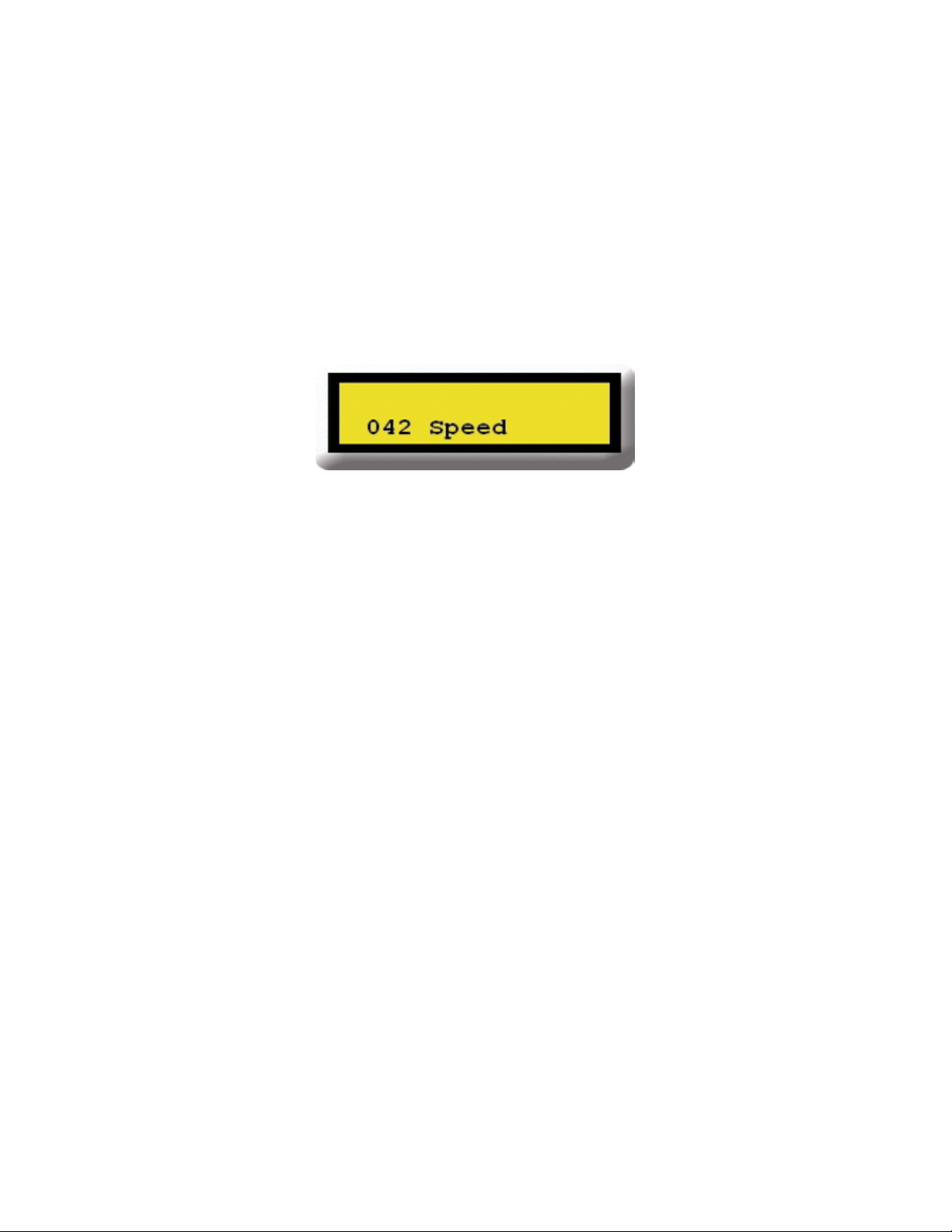
The backlight on the display will turn off after 1 minute of inactivity from the user. If
a card is in the unit, it will continue recording data and display speeds, Figure 3. Press
any key to turn on the backlight again.
Figure 3 – Speed of oncoming vehicles being recorded.
The data is saved in an ASCII text format and can be viewed using the Traffic Count 7
or you can create your own reports and graphs with the raw data and your own
programs like Microsoft Excel®.
A 128MB SD card can save over 6,000,000 vehicle entries. Note that the more
vehicles saved on your card, the longer the reports will take to generate.
Adaptive Micro Systems LLC | 7840 North 86th Street | Milwaukee, WI 53224
Phone (800) 558-7022 | AdaptiveDisplays.com
Section B - In Depth Guide and Setting Commands – Data Recording Unit
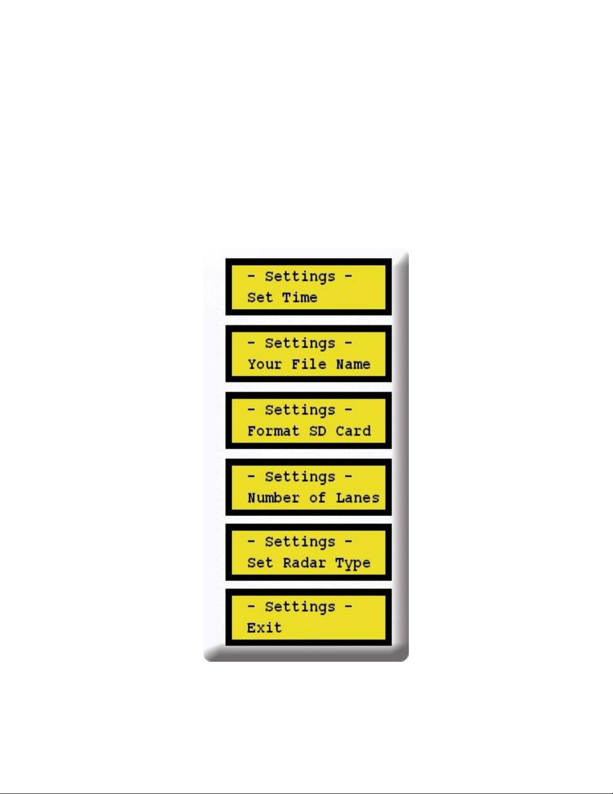
1) The Settings Menu allows you to:
Name your files. This is helpful if you decide to move the trailer to a different location
on the same day. Each file can list, for example, the street name so when you are ready
to run the reports, you can easily identify each location. If you have multiple trailers/
signs, each unit can have a unique name or number.
Erasing data on the SD card can be done while the data recorder is mounted inside the
trailer enclosure (see “Format Card” below).
Note the importance of setting the correct “Road Configurations”. Having the proper
road volume setting will create a more accurate vehicle count.
Use the + and – buttons to navigate thru the Settings Menu. To select the displayed
option, press the Enter button.
Figure 4 - Settings Menu
Adaptive Micro Systems LLC | 7840 North 86th Street | Milwaukee, WI 53224
Phone (800) 558-7022 | AdaptiveDisplays.com
Table of contents


