Adast Systems MAJOR V-line 46 Series Operation and maintenance manual

Adast Systems, a.s., 679 04 Adamov No. 496, Czech Republic
T+420 516 519 201, F+420 516 519 102, sales@adastsystems.cz
www.adastsystems.cz
OÚ/003/2005/MSS/A
XI/2018
USER´S MANUAL
Instructions for Operation, Maintenance
and Installation
Multi-product fuel Dispenser operating by Suction or
Pressure Pumping System
MAJOR
V-line 46xx.xxx
V-line 47xx.xxx


USER’S MANUAL V-line 46xx, 47xx
I
CONTENT
1. IMPORTANT NOTICE ..................................................................................................... 1
2. USE.......................................................................................................................... 2
3. INSTRUCTIONS FOR THE SAFETY OF WORK ........................................................................ 2
3.1. Safety of the equipment design................................................................................2
3.2. Operation safety ..................................................................................................3
3.3. Ecological safety ..................................................................................................3
3.4. Hygiene .............................................................................................................4
4. BASIC DESCRIPTION ..................................................................................................... 4
4.1. Design of dispensers..............................................................................................4
4.2. Hydraulic system of the fuel dispenser .......................................................................5
4.3. Electronics .........................................................................................................7
4.4. Vapour recovery system .........................................................................................8
4.5. Signalling of dispenser conditions (SO) ..................................................................... 19
4.6. SOPA design...................................................................................................... 19
4.7. Design with heating of the electronic case ................................................................ 19
5. TECHNICAL DATA .......................................................................................................19
6. IDENTIFICATION .........................................................................................................25
7. PUTTING OF THE FUEL DISPENSER INTO OPERATION...........................................................26
7.1. Putting the dispenser and electronic counter into operation .......................................... 26
7.2. Shutdown of the dispenser and electronic counter....................................................... 26
7.3. Restart of the dispenser and electronic counter after power failure and voltage drop ........... 26
8. ATTENDANCE ............................................................................................................26
9. DISPENSER OPERATION ................................................................................................27
9.1. Dispensing with preselection ................................................................................. 27
9.2. Description of the preselection function .................................................................. 27
10. FUNCTIONS OF KL-MANINF MANAGER AND KL-SERINF SERVICE KEYBOARDS ..............................27
10.1. Manual setting of unit prices ................................................................................. 28
10.2. Setting of unit price values from the control system in AUTO mode .................................. 28
10.3. Display of electronic totalizers............................................................................... 29
10.4. Check of vapour recovery system function................................................................. 29
11. MAINTENANCE OF A DISPENSER AND ITS INDIVIDUAL OPERATING UNITS...................................30
11.1. Pumping monoblock ............................................................................................ 30
11.2. Piston flowmeter ............................................................................................... 31
11.3. Electromagnetic two-stage valve ............................................................................ 31
11.4. Sight glass of the dispenser ................................................................................... 31
11.5. Dispensing hose ................................................................................................. 31
11.6. Dispensing nozzle ............................................................................................... 31
11.7. V-belt of the pump ............................................................................................. 32
11.8. Dismantling of covers .......................................................................................... 32
11.9. Maintenance instructions for dispenser body parts....................................................... 33

USER’S MANUAL V-line 46xx, 47xx
II
11.10. Electronic counter .............................................................................................. 33
12. DISASSEMBLY AND DISPOSAL .........................................................................................33
13. SUMMARY OF BASIC PRINCIPLES FOR DISPENSER MAINTENANCE .............................................34
14. TRANSPORT ..............................................................................................................34
14.1. Transport of V-line 46xx.xxx, 47xx.xxx fuel dispenser and its putting on the base frame ........ 34
15. DISPENSER INSTALLATION ............................................................................................36
15.1. Hydraulic part ................................................................................................... 36
15.2. Wiring ............................................................................................................. 39
16. PACKING AND STORAGE ...............................................................................................40
16.1. Packing ........................................................................................................... 40
16.2. Storage ........................................................................................................... 40
17. GUARANTEE AND CLAIMING ..........................................................................................40
18. SPARE PARTS CATALOGUE............................................................................................41
19. ACCESSORIES ............................................................................................................41
20. DOCUMENTATION DELIVERED ........................................................................................41
21. ENCLOSURES .............................................................................................................42
USER’S MANUAL V-line 46xx, 47xx
1
1. IMPORTANT NOTICE
This document is a guideline for the user how to proceed when installing, attending and maintaining the
dispenser. The information included in the present instructions are mandatory and the manufacturer does
not accept any responsibility for any damage due to their non-observance.
The dispenser is complicated equipment providing many important functions.
Prior to putting into operation tanks and the piping system shall be cleaned and fuel purity shall be
checked. Also el. power distribution and correct wiring shall be inspected to prevent injury by el.
current and to provide explosion proofness –fuels are flammable liquids of the 1st and 2nd danger class!
The manufacturer tests each dispenser considering the function, safety and metrology. Each delivery shall
include the instructions for attendance, maintenance and installation, EC declaration of conformity and a
service book identifying dispenser components. The dispenser, produced with high precision and care,
secures reliable and safe operation. Principal safety regulations protecting the user against injury shall be
kept during operation and maintenance and the dispenser shall be prevented from damage. No
modifications of the dispenser equipment are allowed without producer’s written approval.
The dispenser has been designed for outdoor installation –class according to OIML D11 –C (outdoor -
stationary).
Important instructions for installation and operation:
a) Study the instructions for attendance, maintenance and installation and other manufacturer’s
documents included within dispenser accessories before you start to handle the equipment.
b) Check the dispenser delivery completeness and inform the manufacturer immediately in case of any
discrepancies or damage.
c) The dispenser shall be stored in a dry and protected room before it is installed at the filling station.
d) Prior to dispenser installation check the completeness of the filling station technology according to the
valid design, check the connecting dimensions of the foundation frame including the piping system
outlet.
e) Rinse the process equipment (piping) through the filtration equipment until impurities are removed.
f) The dispenser requires the connection of the vapour return piping of min. DIN 16 –we recommend DN
25.
g) Wiring and inspection of the dispenser shall be carried out.
h) When putting the dispenser into operation, proceed according to the point 7 of the present instructions.
i) A metrology authority specialist shall perform function test and metrology checking.
j) Being these conditions fulfilled, after the approval of a state supervision authority and the verification
of a metrological office representative, usual operation can be started.
k) Only qualified and trained staff of a service company can perform service and installation. Service
procedures shall be performed in compliance with the operation regulations of the filling station. The
manufacturer is not responsible for damages due to the incompetence of the staff.
l) The owner can only start dispensing when the filling station inspection is finished and a metrology
authority carries out metrological verification of the dispensers.
m) When fuels are pumped, basic hygienical precautions shall be adhered. The owner shall enable the
customer to use protective gloves.
SAVE FOR FUTHER USE!
ATTENTION!
The dispenser shall not be installed in an explosion danger zone 0, 1, 2 in compliance with zones
specified in the EN 60079-10!

USER’S MANUAL V-line 46xx, 47xx
2
2. USE
Multi-product fuel dispensers type series V-line 46xx.xxx and V-line 47xx.xxx with electronic counter
used for the dispensing of liquid petroleum products - automotive petrol, diesel, kerosene, etc., of
alternative liquid fuels (biofuels) - biodiesel (B 10 - B 100) - a mixture of diesel fuel with FAME
(Fatty Acid Methyl Ester) and a mixture of automotive petrol with bioethanol (E10 - E 85) (flammable
liquids I. to IV. hazard class and group explosivity IIA) with dynamic viscosity up to 20 mPa.s and with
flow rate optional 40, 60, 70, 80, 110, 120, 130, 150 dm3. min-1.
Special modification dispensers type series V-line 47xx.xxx/OIL are determined to dispensing liquid
fuels on the base of vegetable oil (rape oil, sunflower oil, soya oil, which are modified for internal
combustion in diesel engines) and mineral oils with maximum dynamic viscosity up to 1000 mPa.s and
with flow rate optional 40, 60, 70, 80 dm3. min-1.
They have been designed for the installation at road filling stations and a fleet of vehicles, etc. By means
of a communication line the dispensers are connected to the control system of self-service operation or
serviced operation.
The dispensers are equipment with special requirements concerning safety, metrology and ecology.
The dispensers are equipped to exhaust vapours; thus ecological operation of filling stations is provided,
i.e. the prevention of harmful petrol vapours leakage into atmosphere.
The instructions for attendance, maintenance and installation serve the user to gain information on the
design, correct attendance, maintenance and safe installation.
3. INSTRUCTIONS FOR THE SAFETY OF WORK
3.1. Safety of the equipment design
The manufacturer guarantees safety of the equipment design.
The dispenser design complies with the EN 13617-1 requirements and it is homologated for the
operation in environment specified by II2G IIAT3 symbols shown on the dispenser plate.
Considering operation safety in environs with explosion danger the dispensers have been EC –type
examination (certification) according to the annex III of the Directive 2014/34/EU –ATEX by an
authorised body FTZÚ, Pikartská 7, 716 07 Ostrava –Radvanice –Notified body no. 1026.
EC - Type Examination Certificate: No. FTZÚ 05 ATEX 0069
Regular inspection of production quality assurance according to Annexes IV and VII of the Directive
2014/34/EU executes FTZÚ, s.p., Ostrava –Radvanice, NO no. 1026.
Notification of quality assurance: No. FTZÚ 02 ATEX Q 020.
Considering legal metrology the dispensers have been EC –type examination (certification) according
to the annex B of the Directive 2014/32/EU –MID by an authorised body Český metrologický institut,
Okružní 31, 638 00 Brno – Notified body no. 1383.
EC - Type Examination Certificate: No. TCM 141/07 - 4505
The producer performed a conformity examination for the fuel dispenser with the type described in
EC –Type Examination Certificate No. TCM 141/07 –4505 and technical requirements according to the
Directive of European Parliament and the Council 2014/32/EU.
The producer is competent for “The Declaration of Conformity” with the type based on production
quality assurance of measuring units according to the Directive Supplement D of European Parliament
and the Council 2014/32/EU.
Certificate of the Quality Management System for production, check-out and testing:
No. 0119-SJ-C007-07.
Regular inspection of production quality assurance, check-out and testing according to the Directive
Supplement D of European Parliament and the Council 2014/32/EU executes authorised body Český
metrologický institut, Okružní 31, 638 00 Brno – Notified body no. 1383.
ATTENTION!
Any handling open flame is prohibited during fuel filling and smoking is prohibited even in vehicles
interior. Also filling vehicle tanks with running motor and any other activities possibly initiating
explosion are prohibited!

USER’S MANUAL V-line 46xx, 47xx
3
3.2. Operation safety
The owner is responsible for the filling station operation and is obliged to follow the course of fuel
pumping. In case a customer uses the dispenser incorrectly, the owner shall instruct him about proper use.
The owner shall also identify the hazard zone of the filling station by warning symbols (smoking prohibited,
open flame prohibited, direction of arrival to dispensers, etc.).
Operation regulations of the filling station shall be accessible for the customer, which enables him to get
information on principal obligations.
Operator’s obligation:
–Keep the equipment in safe and proper condition.
–Follow the operation regulations and attendance instructions of the filling station.
–Report immediately any failure to the owner and put the equipment out of operation in case of delay.
–Keep order permanently.
–The dispenser and storage tank operators are not allowed to repair the equipment and to reset any
safety valves.
Performance of service work is a special case. Servicemen are not allowed to break operation safety
during repairs and other activities. When dispenser covers are removed, they shall be very careful to
protect both them and customers against injury.
El. current supply shall be disconnected when handling el. components. Only approved components
shall be used to replace any parts.
All parts subject to approval shall be always in conditions required by the technical documentation
(leakproofness, earthing, electrostatic belts, electrostatically conductive filling hoses, etc.).
3.3. Ecological safety
In accordance with the „DIRECTIVE 2009/126/EC OF THE EUROPEAN PARLIAMENT AND OF THE COUNCIL
of 21 October 2009 on Stage II petrol vapour recovery during refuelling of motor vehicles at service
stations“must be filling station for dispensing gasoline equipped according to the national legislative
regulations of the country of destination (installation and operation of fuel dispensers) Decree recovery
system (reverse drain stage II petrol vapor - Equipment recuperate (consultation draft) petrol vapor
displaced from the fuel tank of a motor vehicle during refueling and carrying gasoline vapors to the storage
tank at the service station.
IMPORTANT NOTE!:
Terms of service stations and control petrol vapor recovery system stage II is drived by the
"Directive 2009/126/EC of the European Parliament and Council" and the relevant national legal
regulations in force in the countries of destination (installation and operation of fuel dispensers).
Fuel dispensers ADAST V-line 46xx.xxx, 47xx.xxx for dispensing of petrol are equipped with an
efficient recovery system (reverse exhaust vapor) that meets the requirements of the "Directive
2009/126/EC of the European Parliament and Council”:Volumetric efficiency of vapor recovery
shall be between 95-105% - the rate of the volume of recovered vapor at atmospheric pressure to
total dispensed gasoline into the fuel tank of a motor vehicle is equal to or greater than 0,95 but
less than or equal to 1,05.
3.3.1. Check of petrol vapor control system –by the Directive 2009/126/EC
Check of petrol vapor recovery system Stage II at the dispenser shall be in accordance with
Directive 2009/126/ES under the relevant national legislation and regulations applicable in the
countries of destination (installation and operation of fuel dispensers).
Regular checks under Directive 2009/126/EC
1. Checking the operating efficiency of petrol vapor recovery system Stage II must be performed
at least once per year. Checks whether the ratio is the ratio of the volume of paid vapor at
atmospheric pressure to the total volume of gasoline fished into the fuel tank of a motor
vehicle is equal to or greater than 0,95 but less than or equal to 1,05.
2. If the dispensers installed automatic monitoring system, the efficacy of petrol vapor recovery
stage II tested at least once every three years. Any such automatic monitoring system shall
automatically detect faults in the proper function of petrol vapor recovery system Stage II and
in the automatic monitoring system, indicate faults to the service station and automatically
stop the flow of petrol from the faulty dispenser if the fault is not rectified within seven days.

USER’S MANUAL V-line 46xx, 47xx
4
IMPORTANT NOTE!:
All fuel dispensers used for dispensing gasoline must be equipped with clearly labeled, indicating
the need for customers to fully insert the nozzle into the filler neck of the vehicle tank.
Check of petrol vapor recovery system Stage II at fuel dispensers
ADAST MAJOR V-line 46xx.xxx, 47xx.xxx.
To check the operating efficiency of petrol vapor recovery system Stage II are two procedures:
1. Procedure for dispensers where the pump driven by an electric pump without electronic
control system vapor recovery:
The test is performed for pumping petrol into a suitable volumetric container at 50% and 100%
of the nominal flow of petrol. Measuring the effectiveness of this system is carried out solely
for the purpose meter designated as a special meter Bürkert G4-RF1 connected to the suction
nozzle attachment with a universal connector UMAX 2 companies ELAFLEX).
2. Procedure for dispensers with electronically controlled petrol vapor recovery system Stage
II, which allows to perform the test without using gasoline:
The test is carried out so-called "dry way" apparatus approved for this purpose - eg special
meter Bürkert G4-RF1 connected to the suction nozzle attachment with a universal connector
UMAX 2 companies ELAFLEX). Gas meter Bürkert G4-RF1 is via pulse output is connected
through a special cable to enter the electronic counter. Linking meter counter and must be
done at a gas station through the reduction of RP/M/EX, which contains zener barrier for
intrinsic safety.
3.4. Hygiene
The dispensers are hygienically harmless for customers and the owner. But protective gloves are advised to
be used during maintenance or filling fuel.
In case skin comes to contact with fuel or impurities, wash the spot with water and soap as soon as
possible. When eyes come to contact, medical treatment is necessary. Do not inhale harmful vapours when
filling fuel.
4. BASIC DESCRIPTION
4.1. Design of dispensers
Skeleton –a self-supporting structure consisting of parts with high anticorrosive resistance. The base of the
dispenser is made of steel sheet and heat zinc-coated. Internal parts of the skeleton are made of galvanised
sheet. Parts of the body with the exception of the door of the hydraulic module and the electronic counter
case are made of stainless brushed sheet as a standard.
High resistance acrylurethane enamel is applied on the hydraulic module door and the electronic counter
case. The colour shade of the door including the logo can be optional.
The subframe of the dispenser is manufactured and delivered in two modifications depending upon the
design of the lower part of the filling station equipment:
-without drip-pan –the drip-pan is a part of the lower equipment
-with drip-pan –the drip-pan is glued into the dispenser base with bonding and sealing cement
Both doors are lockable; being unlocked, swing out and with earth wire disconnected they can be removed
and thus the hydraulic part including electric switch box are accessible. Connect the earth wires when the
door is fitted back.
4.1.1. Case of the electronic counter
A case of the electronic counter or ADAMAT electronics is bolted to the hose module column. The counter
case space is closed with lockable covers. The covers are provided with transparent glass. Indicators with
integrated large-area display of dispensed volume, total price of dispensed volume and a price for one unit
of dispensed volume are connected from the case interior to the covers or unresetable electromechanical

USER’S MANUAL V-line 46xx, 47xx
5
total counters (totalizers). The set of these elements represents all necessary information for the
customer.
The covers of the case are hung up on hinges enabling tilting upwards after unlocking and thereby easy
access in the case interior. The user’s local preselection keyboard is located on the case cover as well.
4.1.2. Case of the electronic counter –design 2017 (see fig.)
A case (1) of the electronic counter or ADAMAT
electronics is bolted to the hose module column.
The counter case space is closed with lockable
covers (2). The covers are provided with
transparent glass.
On the inside cover of the case is mounted under
glass large-area display (3) issued volume and total
price, which displays all necessary information for
the customer.
Above the display is placed IR sensor (5) for
controlling and adjusting the dispenser calculator
manager or servicing keyboard.
On the outer side of the case cover is placed
(optional) keyboard local user preferences (4).
On request they can be built in a case unresetable
electromechanical total counters –totalizers (6),
which are accessed by opening the cover.
ATTENTION!
Before opening the covers, it is always necessary to disconnect power to the dispenser and perform
a reliable hedge against its re-connection.
The dispensers of the V-line 46xx.xxx, V-line H, R 47xx.xxx type series are manufactured in two
modifications differing in the design:
-V-line H –high design of the hose module with free hanging dispensing hoses
-V-line R –low design of the hose module with winding gear of hoses
The dispensing nozzles are seated in covers in the „V“ form pressed shape of the column and bearers of the
hose module. When the dispenser is out of operation the dispensing nozzles in covers can be locked.
With respect to the application the dispensers of the V-line H, R 46xx.xxx, V-line H, R 47xx.xxx type series
are supposed to be installed at the following filling stations:
-V-line H, R 46xx.xxx –for filling stations with the suction system of pumping
-V-line H, R 47xx.xxx –for filling stations with central pressure distribution system
4.2. Hydraulic system of the fuel dispenser
The integrated hydraulic unit consists of a pumping monoblock with an integrated large-surface filter, a
meter with integrated impulse sensor connected with the pumping monoblock through a special joining
piece and a driving el. motor of the pump.
Pumping monoblock type series P 64x.xxx/x –is an independent unit for one kind of the pumped fuel. An
integrated compact structure contains an efficient filter, sliding vane pump, control and non-return valves,
safety relief valve with continual control of the operating pressure, cyclone (centrifugal) gas separator and
a venting chamber with a float valve. Progressive design provides 100% separation of gaseous components
and automatic blocking of filling when excessive amount is identified in the product pumped.
The large-surface filter with an integrated non-return valve and standard filtration efficiency 30 µm for
petrol and optional 30 µm or 60 µm for Diesel oil (winter operation in extreme low temperatures).
The pumped liquid passes through the filter and the non-return valve to the pump and the separator where
gases and vapours are separated and pass to the float chamber. Condensed liquid is discharged to the
suction part of the pump and gases are exhausted to the vented part of the dispenser base. The liquid is
discharged from the non-return valve to the meter, then through an electromagnetic valve into the
dispensing hose with a dispensing nozzle at its end. The dispensing nozzle lever controls the rate flow. A
tube sight glass can be installed between the dispensing hose and the nozzle for visual checking.
A three-phase asynchronous motor drives the pump by means of an antistatic V-belt.

USER’S MANUAL V-line 46xx, 47xx
6
Special modification of the pumping monoblok of P 64x.xxx/x/BIO series is intended to pumping of
biofuels - biodiesel (B 10 - B 100) - a mixture of diesel fuel with FAME (Fatty Acid Methyl Ester) and
a mixture of gasoline with bioethanol (E10 - E 85) . It has a special surface protection, which
ensures their high resistance against aggressive biofuels.
Dispensers V-line 47xx.xxx series (pressure design) differ from suction dispensers because they are not
equipped with the pumping monoblock. A safety breaking valve shall be fitted in the connection. The valve
prevents fuel leakage in case of the dispenser damage. This valve is not a part of the dispenser, as well as
the pump, which is located in the underground tank. The pressure dispensers are equipped with an inlet
spherical valve for closing the liquid input in case of repairs.
The pumped liquid is supplied from the central submerged pump located directly in the fuel storage tank
through the safety breaking valve, spherical check valve and the filter with filtering property of 30 µm or
10, 20 µm (optional) for petrol and 30 or 60 µm for Diesel oil. Liquid is discharged from the filter through
the meter and the electromagnetic valve to the dispensing hose with the dispensing nozzle at its end. The
dispensing nozzle lever controls the rate of flow. The tube sight glass can be fitted between the dispensing
hose and the nozzle for visual checking.
Meter type series M 403xxxx/x is composed of a four-piston all-aluminium meter and an integrated
magnetic pulse transmitter. The original meter ensures metering accuracy within a wide range of flow
rates 4 - 150 dm3.min-1 and fuel operating temperatures -20 °C to +50°C (-10 °C to +50°C for biodisel
B 70 to B 100) and ambient temperatures -40 °C to +60°C for nominal pressure up to 0,32 MPa.
The new design made of special materials considerably improves the accuracy and reliability. The universal
design for both mechanical and electronic calibration is an advantage. A two-channel integrating impulse
generator is a part of the meter. The number of impulses is proportional to the swivelling angle of the shaft
and the runoff volume of fuel.
The impulser generates 2 x 100 impulses per 1 dm3. The meter is electronic calibrated by an el. meter
processor with the help of the service keyboard.
Meters are supplied with optional integrated magnetic pulse transmitter Eltomatic ME 01-05 - type
designation M 403.25P, M 403.32P, M 403.25EP, M 403.32EP or with a magnetic pulse transmitter
METRA MTX 075 or ADAST 40 - type designation M 403.25P/1, M 403.32P/1, M 403.25EP/1, M
403.32EP/1.
Special modifications to the type of meters M 403.25хP/B, M 403.25хP/B/1, M 403.32хP/B,
M 403.32хP/B/1 is intended to measure the volume of biofuel - a mixture of gasoline with
bioethanol (E10 - E 85).
Meters with the designation /В have special surface protection, which ensures their high resistance
against aggressive biofuels.
Meters with the designation of EP in electronic calibration, indicating P mechanical calibration
Electric motors –El. motors 0,55 kW, 0,75 kW, 1,1 kW for pumping and 0,37 kW, or 0,18 kW for vapours
exhaustion are used in the V-line 46xx.xxx suction dispensers.
El. motors 0,37 kW, or 0,18 kW h for vapour exhaustion are used in the V-line 47xx.xxx suction dispensers.
The number of the pumping monoblocks, meters and el. motors is specified according to the dispenser
type.
Dispensing hoses –single and coaxial dispensing hoses meet the requirements of the EN 1360. The
dispensing hose is located in the hose part of the module, which ensures the safekeeping of the hose when
the dispenser is out of operation. In case of fuel filling it enables to pull the hose out in needed length.
Backward safekeeping of the hose into the hose module is enabled by dead weight of the dispensing hose
when the nozzle is suspended or by means of a winding gear.
For pumping biodiesel (B 10 - B 100) - a mixture of diesel fuel with FAME (Fatty Acid Methyl Ester)
must use a special hose for biodiesel - Elaflex Slimline BIO!!
Dispensing nozzles –are supplied according to the Client’s option. The nozzles are automatic, fitted with a
swivelling joint and an effective STOP system used in case of the tank overfilling or in emergency situation.
The nozzles can be fitted with safety disconnecting joints according to the Client’s option. The dispensing
nozzle is hung in the nozzle cover and it is lockable when the dispenser is out of operation.
The dispensers are equipped with electromagnetic (solenoid) valves ON/OFF (double stage), or
electromagnetic proportional valves as a standard.

USER’S MANUAL V-line 46xx, 47xx
7
4.3. Electronics
The dispenser control shall meet the exacting requirements of simplicity and convenience and depends on
the hanging up and lifting of the dispensing nozzle.
ADPMPD/T, ADPMPD/T-PWM, ADP1/T, ADP2/T, ADP1/L electronic counter of an up-to-date design with
central processor board equipped with a high efficient microprocessor. The configuration of the counter
and its modes of operation are adjusted by more than seventy parameters. The counter is provided with a
self-diagnostic system. The counter outlets control the motors, valves, signalling circuits and vapours
exhaustion. The electronic counter processes the impulses coming from the impulse sensor and transmits
them to the display, which displays the dispensed volume, its price and a price per a volume unit. In case
of power failure or voltage drop the data displayed on the LCD remain for 30minutes at least.
Counters ADPMPD/T, ADP1/T, ADP2/T, ADP1/L are standardly equipped for electronic meter calibration
(Electronic Calibration of Meters –EC) and per request by ATC –(Automatic Temperature
Compensation).
Electronic Calibration of Meters (EC) enable to correct measured volume by designed declination in
operation range -5,00 % to +5,00 % of recognised meter non accurancy by step of 0,05 %.
Automatic Temperature Compensation (ATC) is designed to compensate temperature expandity of
dispensed medium based on measured temperature during dispensing. For temperature measuring is used
approved certified temperature sensor –resistance temperature sensor PT 100, in fuel dispensers V-line
46xx.xxx build in entering angle to pumping monoblock and in fuel dispensers V-line 47xx.xxx build in
pipeline after the filter unit.
Calibration tablets for ATC on designed medium (type of fuel) can be integrated into SW of electronic
counter by customer request. Setting of calibration EC or ATC is provided by using of service keyboard KL-
SERINF and setting of proper calibrating switches DIP on body of electronics counter as per instructions
described in manual of electronic counters ADP1/T, ADP2/T or ADPMPD/T.
Providing of calibration is allowed to authorised person, only. The DIP calibration switches must be fixed by
plomb after calibration finish.
Displays: LCD type with BACK LIGHT illumination
LCD displays with BACK LIGHT DISPLAY (BLD) illumination are used especially for their good readability.
The duration of data holding on the display after supply voltage failure is 30 minutes at least. Decimal point
on BLD display devices is represented automatically in accordance with the setting of parameters.
Lighting
LED diodes are used for the illumination of displays at dispensers.
ON / OFF switching of the illumination is automatically carried out with the activation of electronics.
Totalizer: non-resettable electronic counter of dispensed volume and its price –11 digits –or non-
resettable electromechanical counter of dispensed volume –7 digits.
Electronic counter of ADPMPD/T, ADPMPD/T-PWM, ADP1/T, ADP2/T, ADP1/L series operates with a 2-
channel impulse generator producing 2x 100 impulses per 1 dm3. The HW and SW counters of the
ADPMPD/T, ADP1/T, ADP2/T, ADP1/L series enable high metering accuracy and the application of the
electronic calibration using the 2-channel impulse generator.
The local electronic preselection system in IP67 design is integrated into the counter case. The
preselection enables the Customer’s preselection of the exact volume or the price of the product to be
dispensed. The two-stage or proportional electromagnetic valves ensure the closing of flow and exact
dispensing of the preselected volume / price and smooth initiation of dispensing.
The fuel dispensers can be equipped with ADAMAT filling automatic equipment. This equipment enables
dispensing and payment of the product by means of contactless, magnetic and chip cards including receipt
printing. This equipment undertakes simultaneously all functions of the dispenser electronic counter for
non-public and public dispensing. The electronics of the filling automatic equipment can be complemented
by the ADPMPD/T, ADP1/T, ADP2/T, ADP1/L electronic counter with public dispensing.
The fuel dispenser is connected through a communication line to the control system, which controls the
operation of the whole filling station (releasing of dispensers, volume preselection, unit price variation,
self-diagnosis, etc.). The dispensers can be operated even at the filling stations without any control system
–i.e. in serviced operation.
Circuit diagrams for the connection of individual dispenser types to the switchboard of the filling station –
see enclosures.
USER’S MANUAL V-line 46xx, 47xx
8
4.3.1. Communication to the control system
The dispensers are equipped with ADPMPD/T, ADP1/T, ADP2/T, ADP1/L electronic counters, which are able
to communicate to POS Win control systems. A communication serial interface RS 485 or a communication
standard IFSF LON are used for the communication of electronic counters to the superior control system.
Communication to different control systems shall be consulted with the manufacturer of the dispensers in
advance.
The fuel dispensers connected to the control system can be operated in the mode of volume preselection or
the financial sum preselection from the control system (the dispensers have to be equipped with two-
stage or proportional electromagnetic valves).
The POSWIN control system (POS Win EURO) enables the process control and the sale of goods according
to stock cards (999 999 items in 99 groups) including storage facilities. Systems are identical with respect to
the communication to the dispensers; they communicate on the principle of the bus interface RS 485. This
systems combine the basic functions of the filling station, i.e. sale of fuels, sale of dry goods and their
filing. POS system is also able to operate even as a multi-cash one, i.e. its individual parts can be
interconnected in the communication SW network with two backoffices and three tills. If more than five
backoffices or tills are connected, a server has to be included.
4.4. Vapour recovery system
Fuel dispensers ADAST POPULAR type line V-line 46xx.xxx, 47xx.xxx are supplied in the following
modifications of petrol vapor recovery systems :
1
System VRC-M
Vapour Recovery Control –Mechanical - control the flow of vapor by
hydromechanical proportional valve integrated into nozzle (Elaflex).
2
System VRC-E
Vapour Recovery Control –Electronic –control the flow of vapor through the
proportional solenoid valve directly controlled by an electronic control unit
dispenser (single-chip microcontroller electronic counter).
3
System VRC-M
+ VRMS
System VRC-M with automatic control system –VRMS (Vapour Recovery
Monitoring System).
VRMS system independently monitors system VRC-M - detect faults in the
proper function recovery system Stage II petrol vapor and VRMS system
itself, indicate faults to the service station and automatically stops the
flow of petrol from the faulty dispenser (dispensing areas), if the fault is
not rectified within seven days.
4
System VRC-E
+ VRMS
System VRC-E with automatic control system –VRMS (Vapour Recovery
Monitoring System).
VRMS system independently monitors system VRC-E - detect faults in the
proper function recovery system Stage II petrol vapor and VRMS system
itself, indicate faults to the service station and automatically stops the
flow of petrol from the faulty dispenser (dispensing areas), if the fault is
not rectified within seven days.
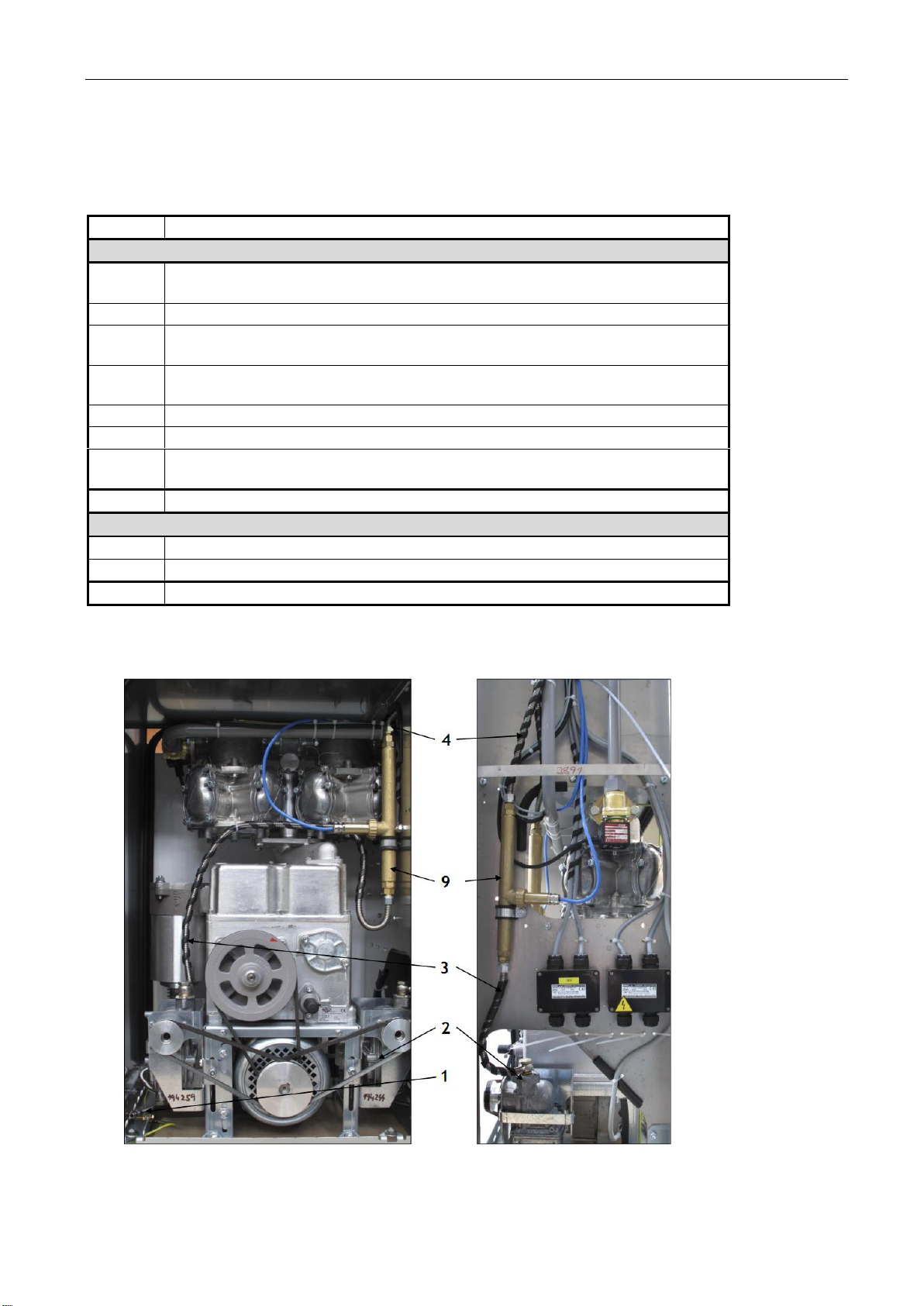
4.4.1. Systém VRC-M
Vapour Recovery Control –Mechanical - control the flow of vapor by hydromechanical proportional valve
integrated into nozzle (Elaflex GRVP).
Vapor recovery system VRC-M of the dispensers V-line 46xx.xxx, 47xx.xxx consists of the following
basic components (structural layout and design is evident from Figures 1, 2, 3, 4, 5):
Position
Unit name
1
Flexible pipe with union nut M 16 x 1,5 for connection to outgoing pipe into
storage tank.
2
Piston vacuum pump
3
Flexible connecting pipe between the vacuum pump and coaxial interpiece
4
Coaxial interpiece for connecting of coaxial delivery hose
5
Coaxial delivery hose
6
Delivery nozzle for vapour recovery with integrated hydromechanical
proportional valve (ELAFLEX GRVP)

USER’S MANUAL V-line 46xx, 47xx
9
Pic. 2
Function of system VRC-M
The vacuum in the VRC-M system is created by piston vacuum pump (Item 2), which is powered via a rubber
belt of electric motor of pumping monoblock. For dispensers with pressure system is installed in a compact
unit - electric motor with integrated vacuum pump.
Outgoing gasoline vapors from the tank car when dispensing gasoline are drawn special adapter nozzle
(item 6), through the channel in the body to control flow through the nozzle hydromechanical valve
integrated into nozzle and into the inner coaxial hose DN 8 (Item 5). The coaxial spacer (Item 4) pairs are
fed to a flexible connecting pipe (Item 3), goes on to piston pumps (Item 2). The piston pump (item 2) are
pushed through a flexible pipe to the exhaust pipe vapor (Item 1). connected to the interior of the storage
tank (usually from the lowest octane gasoline.
Optimal flow of vapor is dynamically regulated by proportional hydromechanical valve depending on the
actual flow of liquid gasoline nozzle.
Proper function of vapor recovery is indicated by shining symbol of two arrows (Fig. 9) on the display of
electronic counter on the appropriate side of the dispenser.
Pic. 3
Pic. 4
System VRC non functional
System VRC is functional
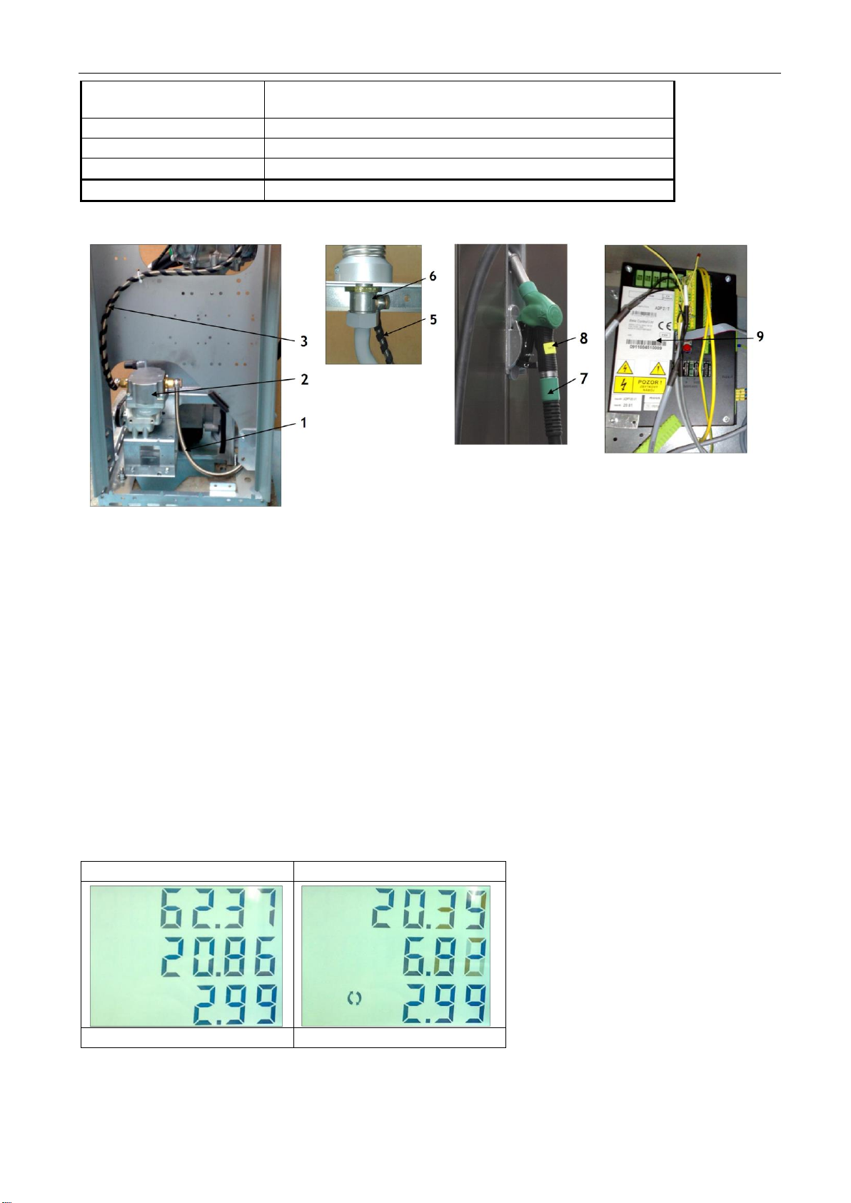
4.4.2. System VRC-E
Vapour Recovery Control - Electronic - control the flow of vapor through the proportional solenoid
valve controlled electronic counter dispenser.
Vapour recovery system VRC-E of fuel dispensers V-line 46xx.xxx, 47xx.xxx consists of the following
basic components (structural layout and design is evident from Figure 1, 2:
Position
Unit name
1
Flexible pipe with union nut M 16 x 1,5 for connection to
outgoing pipe into storage tank.
2
Piston vacuum pump
3
Flexible connecting pipe between the vacuum pump and
electromagnetic proportional valve
4
Electromagnetic proportional valve
USER’S MANUAL V-line 46xx, 47xx
10
5
Flexible connecting pipe between the electromagnetic
proportional valve and coaxial interpiece
6
Coaxial interpiece for connecting of coaxial delivery hose
7
Coaxial delivery hose
8
Delivery nozzle for vapour recovery
9
Electronic counter ADP1/T, ADP2/T
Pic. 5
Function of system VRC-E
The vacuum in the VRC-M system is created by piston vacuum pump (Item 2), which is powered via a rubber
belt of electric motor of pumping monoblock. For dispensers with pressure system is installed in a compact
unit - electric motor with integrated vacuum pump.
Outgoing gasoline vapors from the tank car when dispensing gasoline are drawn special nozzle adapter
nozzle (pos. 8) through the channel in the body of the nozzle flow through the inner coaxial hose DN 8 (pos.
7). Inside of coaxial interpiece (pos. 6) pairs are guided to a flexible connecting pipe (pos. 4), then proceed
to the proportional solenoid valve (pos. 4). From the proportional valve through conecting flexible pipe
(pos. 3) guided to piston vakuum pump (pos. 2). From the piston pump (pos. 2) are drawn through flexible
pipe to outgoing pipe of petrol vapours (pos. 1) connected to imide space of storage tank (usually the
lowest octane gasoline tank).
Optimal flow of vapor is dynamically regulated by proportional solenoid valve directly controlled electronic
counter, depending on the flow rate of liquid gasoline respective meter. Electronic counter controls the
flow of vapor based on information about the volume flow meter calculator from magnetic pulse
transmitter.
Proper function of vapor recovery is indicated by shining symbol of two arrows (Fig. 9) on the display of
electronic counter on the appropriate side of the dispenser.
Pic. 3
Pic. 4
System VRC non functional
System VRC is functional
USER’S MANUAL V-line 46xx, 47xx
11
4.4.3. System VRC-M with VRMS
Vapour Recovery Control - Mechanical - flow control vapor through hydromechanical proportional valve
integrated into nozzle (ELAFLEX) controlled system VRMS (Vapor Recovery Monitoring System).
Systems VRC-M and VRMS working separately (independently).
Complete system VRC-M + VRMS contains following components(as on pic. 3, 4, 6, 7, 8, 9):
Position
Unit name
Components of system VRC-M
1
Flexible pipe with union nut M 16 x 1,5 for connection to outgoing pipe into
storage tank.
2
Piston vacuum pump
3
Flexible connecting pipe between the vacuum pump and measuring probe
VAPORIX-Flow
4
Flexible connecting pipe between measuring probe VAPORIX-Flow and coaxial
interpiece
5
Coaxial interpiece for connecting of coaxial delivery hose
6
Coaxial delivery hose
7
Delivery nozzle for vapour recovery with integrated hydromechanical
proportional valve (ELAFLEX GRVP)
8
Electronic counter ADP1/L, ADP1/T, ADP2/T
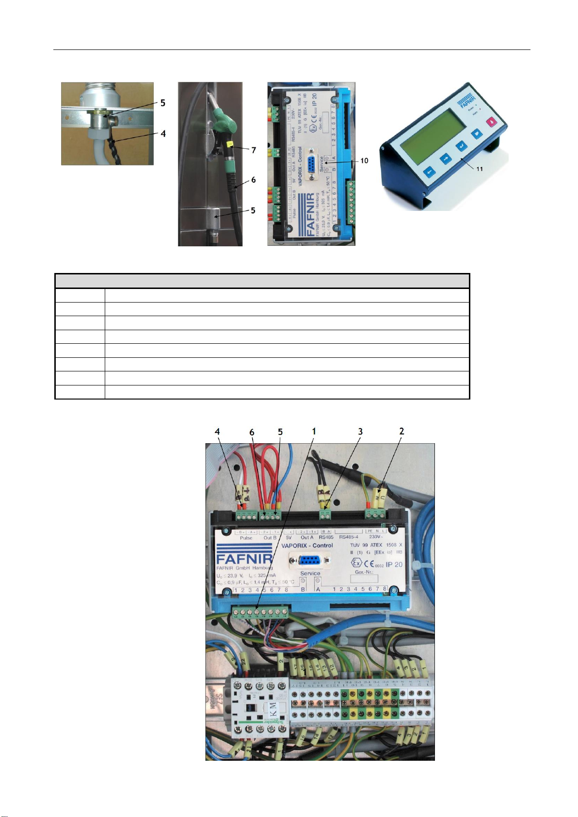
Components of system VRMS –Fafnir VAPORIX
9
Measuring probe of vapour flow Fafnir VAPORIX-Flow
10
Electronic unit VAPORIX-Control
11
Electronic control unit VAPORIX-Master
Pic. 6
USER’S MANUAL V-line 46xx, 47xx
12
Pic. 7
Electronic connection of unit VAPORIX-Control
1
Terminal block for connection of measuring probe VAPORIX-Flow
2
Terminal block for connection of input power
3
Output –communication line for connecting of unit VAPORIX Master
4
Pulse inlet from the module VAP of electronic counter
5
Out A(B) 1 –NC contact „STOP“ – red diode
6
Out A(B) 2 - NO contact „ALARM“ – orange diode
7
Indicating LED-diode for side „A“
8
Indicating LED-diode for side „B“
Pic. 8

USER’S MANUAL V-line 46xx, 47xx
13
Pic. 9
4.4.4. System VRC-E with VRMS
Vapour Recovery Control - Mechanical - flow control vapor through hydromechanical proportional valve
integrated into nozzle (ELAFLEX) controlled system VRMS (Vapor Recovery Monitoring System).
VRC-M Systems and VRMS working separately (independently).
Complete system VRC-E + VRMS contains following components (as pic. 3, 4, 15, 16)
Position
Unit name
Components of system VRC-E
1
Flexible pipe with union nut M 16 x 1,5 for connection to outgoing pipe into storage tank.
2
Piston vacuum pump
3
Flexible connecting pipe between the vacuum pump and electromagnetic proportional valve
4
Regulation electromagnetic proportional valve
5
Flexible connecting pipe between the vacuum pump and measuring probe VAPORIX-Flow
6
Flexible connecting pipe between the measuring probe VAPORIX-Flow and coaxial interpiece
7
Coaxial interpiece for conection of coaxial delivery hose
8
Coaxial delivery hose
9
Delivery nozzle for vapour recovery
10
Electronic counter ADP1/T, ADP2/T
Components of system VRMS –Fafnir VAPORIX
11
Measuring probe of vapour flow Fafnir VAPORIX-Flow
12
Electronic unit VAPORIX-Control
13
Electronic control unit VAPORIX-Master

USER’S MANUAL V-line 46xx, 47xx
14
Pic. 15
Pic. 16

USER’S MANUAL V-line 46xx, 47xx
15
Pic. 10 Scheme of inputs and outlets of the unit VAPORIX-Control

USER’S MANUAL V-line 46xx, 47xx
16
Function of system VRC-M with VRMS
Function of system VRC-M
The vacuum in the VRC-M system is created plunger vacuum pump (Item 2), which is powered via a rubber
belt electric pumping monoblock. For dispensers with pressure system is installed in a compact unit with
integrated electric pump.
Outgoing gasoline vapors from the tank car when dispensing gasoline are drawn special adapter nozzle
(item 7), through the channel in the body to control flow through the gun hydromechanical valve integrated
into nozzle and into the inner coaxial hose DN 8 (Item 6). The coaxial spacer (Item 5) pairs are fed to a
flexible connecting pipe (Item 4), then proceed to the measurement sensor VAPORIX-Flow (poz.9) and then
connecting flexible pipe (Item 3) to the piston pump (pos. 2). The piston pump (item 2) are pushed through
a flexible pipe (Item 1) into the duct connected to the vapor inside the storage tank (usually from the
lowest octane gasoline).
Optimal flow of vapor is dynamically regulated proportional hydromechanical valve depending on the actual
flow of liquid gasoline nozzle.
Proper function of vapor recovery is indicated by shining symbol of two arrows (Fig. 9) on the display of
electronic counter on the appropriate side of the dispenser.
Pic. 3
Pic. 4
System VRC non functional
System VRC is functional
Function of system VRMS:
Automatic Monitoring System (VRMS) VAPORIX dynamically controls the system to function properly VRC.
Measuring sensor VAPORIX-Flow (Item 9) indicates the instantaneous flow and vapor flow rates found online
transmitted to the evaluation unit VAPORIX-Control (Item 10), which compares these values with the values
given volume of liquid gasoline from the transmitted pulse output electronic counter (Item 8) into the
VAPORIX-Control - Connection Figure 6 (Item 4).
The operational statue of the system can notify the operator VRMS at the kiosk station via electronic
unit VAPORIX-Master, which is usually located near the pumping station control system - POS. VAPORIX-
Control Units and VAPORIX-Master are communicatively connected via RS 485 interface using a
communication cable.
Function of system VRC-E with VRMS
Function of system VRC-E
The vacuum in the system VRC-E is generated plunger vacuum pump (Item 2), which is powered via a
rubber belt electric pumping monoblock. For dispensers with pressure system is installed in a compact unit
with integrated electric vacuum pump.
Outgoing gasoline vapors from the tank car when dispensing gasoline are drawn special adapter nozzle
(Item 9), through the channel in the gun body flowing into the inner coaxial hose DN 8 (Item 8), attached to
the coaxial spacer (item 7). The coaxial spacer (item 7) are fed to the steam flexible connecting pipe (Item
6), then proceed to the measurement sensor VAPORIX-Flow (poz.11) and then connecting flexible pipe
(item 5) to control the proportional solenoid valve. The valve is kept flexible pipe (Item 3) to the piston
pump (Item 2). The piston pump (item 2) are pushed through a flexible pipe (Item 1) into the duct
connected to the vapor inside the storage tank (usually from the lowest octane gasoline).
Optimal flow of vapor is dynamically regulated by the proportional hydromechanical valve depending on the
actual flow of liquid gasoline trought delivery nozzle.
Proper function of vapor recovery is indicated by shining symbol of two arrows (Fig. 9) on the display of
electronic counter on the appropriate side of the dispenser.
This manual suits for next models
1
Table of contents
Other Adast Systems Dispenser manuals


Popular Dispenser manuals by other brands


Silver King
Silver King Majestic SK10MAJ Technical manual and replacement parts list

NCR
NCR Retrofit OPTIC 5 Touch installation guide

Ecolab
Ecolab SCLS IV Installation and operation manual

Franke
Franke STRATOS STRX635B Installation and operating instructions

Sartorius
Sartorius Microsart e.motion 16713 BO operating instructions

lancer
lancer 9000 series Operation manual