Adast Systems AdBlue V-line 47 Series User manual

Adast Systems, a.s., 679 04 Adamov No. 496, Czech Republic
T +420 516 519 201, F+420 516 519 102, sales@adastsystems.cz
www.adastsystems.cz
MKT 010-004-2007/A
VII/2017
USER´S MANUAL
Instructions for Operation, Maintenance
and Installation
AdBlue® dispenser
MAJOR
V-line AdBlue®47xx.xxx


USER’S MANUAL V-line AdBlue®47xx.xxx
I
OBSAH
1. IMPORTANT NOTICE................................................................................................................................1
2. USE.............................................................................................................................................................2
3. INSTRUCTIONS FOR THE SAFETY OF WORK ......................................................................................2
3.1. Safety of the equipment design ......................................................................................................2
3.2. Operation safety..............................................................................................................................3
3.3. Ecological safety.............................................................................................................................3
3.4. Hygiene...........................................................................................................................................3
4. DESCRIPTION ...........................................................................................................................................4
4.1. Design of the dispenser ..................................................................................................................4
4.2. Skeleton of the dispenser ...............................................................................................................4
4.2.1 Case of the electronic counter ........................................................................................................4
4.2.2 Case of the electronic counter –design 2017 (see fig.)..................................................................4
4.3. Hydraulic system of V-line AdBlue®47xx.xxx dispenser................................................................6
4.3.1 Filter................................................................................................................................................8
4.3.2 Piston flow meter............................................................................................................................8
4.3.3 Electromagnetic(solenoid) valve ....................................................................................................9
4.3.4 Delivery hose AdBlue®.....................................................................................................................9
4.3.5 Delivery nozzle AdBlue®..................................................................................................................9
4.3.6 Connection elements ......................................................................................................................9
4.4. Electronics.......................................................................................................................................9
4.4.1 Communication to the control system .........................................................................................10
4.5. Signalling of dispenser conditions (SO)........................................................................................10
4.6. SOPA design.................................................................................................................................11
4.7. Design with heating of the electronic case ...................................................................................11
4.8. Heating of hydraulic housing.........................................................................................................11
5. TECHNICAL DATA..................................................................................................................................11
6. MARKING.................................................................................................................................................12
7. INSTALLATION........................................................................................................................................12
7.1. Hydraulic part................................................................................................................................12
7.2. Wiring............................................................................................................................................13
8. PUTING INTO OPERATION ....................................................................................................................13
8.1. Puting of the AdBlue® dispenser to operation mode.....................................................................13
8.2. Puting of AdBlue® dispenser to OFF mode...................................................................................14
8.3. New reseting of AdBlue® dispenser into operation after power supply failure..............................14
9. OPERATION.............................................................................................................................................14
10. FUNTION OF MANAGER AND SERVICE KEYBOARD.........................................................................14
10.1 Manual setting of unit prices.........................................................................................................15

USER’S MANUAL V-line AdBlue®47xx.xxx
II
10.2 Setting of unit price values from the control system in AUTO mode............................................ 16
10.3 Display of electronic totalizers...................................................................................................... 16
11. MAINTENANCE OF A DISPENSER AND ITS INDIVIDUAL OPERATING UNITS ............................... 17
11.1. Filter.............................................................................................................................................. 17
11.2. Piston flowmeter........................................................................................................................... 18
11.3. Electromagnetic two-stage valve ................................................................................................. 18
11.4. Sight glass of the dispenser......................................................................................................... 18
11.5. Dispensing hose........................................................................................................................... 18
11.6. Dispensing nozzle ........................................................................................................................ 18
11.7. Dismantling of covers................................................................................................................... 18
11.8. Electronic counter......................................................................................................................... 19
11.9. Maintenance instructions for dispenser body parts...................................................................... 19
12. SUMMARY OF BASIC PRINCIPLES FOR DISPENSER MAINTENANCE ........................................... 20
13. DISASSEMBLY AND DISPOSAL........................................................................................................... 20
14. TRANSPORT........................................................................................................................................... 20
15. PACKING AND STORAGE..................................................................................................................... 21
15.1. Packing......................................................................................................................................... 21
15.2. Storage......................................................................................................................................... 21
16. GUARANTEE AND CLAIMING............................................................................................................... 21
17. SPARE PARTS CATALOGUE................................................................................................................ 22
18. ACCESSORIES....................................................................................................................................... 22
19. DELIVERED DOCUMENTATION ........................................................................................................... 22
20. ENCLOSURES ........................................................................................................................................ 22

USER’S MANUAL V-line AdBlue®47xx.xxx
1
1. IMPORTANT NOTICE
This document is user guide, how to provide installation, operation and maintenance and service of AdBlue®
dispenser.
Stated information in this manual is strictly recomended and producer can not response for damages
caused by non keeping rules described in this guide.
ATTENTION!
AdBlue® dispenser V-line 47xx.xxx AdBlue®designed for filling stations is determined only for
delivery of reduction medium AUS 32 ISO 2224.
It is not allowed to use such AdBlue® dispenser for delivery of flammable fluids !
ATTENTION!
AdBlue®is solution of pure urea and desalted clear water with 32,5 % content of urea.
Solution is used as reducing agent for lowering of nitrogen emissions NOx in diesel powered engines –
in special SCR catalysator (SCR –„selective catalytic reduction“).
AdBlue®is highly corrosive !
AdBlue®begins to crystalize at a temperature –11 oC!
To guarantee proper function of SCR catalysator in motor vehicle is necesarry to provide regullar
check of solution quality AdBlue®as per norm ISO 22241!
Quality, chemical consistence and physical characteristic of solution AdBlue®must be in accordance
with norm ISO 22241-1!
International marking of reducing agent AdBlue®:
AUS 32 ISO 22241
Therefore before puting AdBlue® dispenser into operation must be checked clean surface of storage
tank(s), entering pipeline(s) and purity of dispensed medium - AdBlue®. Further must be provided
revision of power wiring and check of electric connections, to prevent electric shock.
Every AdBlue® dispenser is tested in production plant for funtionality, safety and metrology. Every delivery
contains user´s manual , ES declaration of conformity and service book with units identification of the
AdBlue® dispenser. AdBlue® dispenser is designed and produced carefully to provide long term safety
work.During installation and operation must be kept basic safety rules to prevent device user from
potential injuries.
It is not allowed to provide any hardware changes without written permit of the manufacturer.
Important instructions for installation and operation:
a) Please study carefully the user´s manuall and other documentation efore manipulation with the AdBlue®
dispenser.
b) Please study the delivery content and if you find any discrepancy inform the supplier imediatelly.
c) In time period before installation the AdBlue® dispenser provide storage inside dry protected space.
The AdBlue® dispenser can not be stored in place with temperature bellow zero(freezing space).
d) Before the installation check completnes of technology as per valid project and check the delivery
pipelines including the connecting fittings.
e) Provide the flushing of technological unit (pipeline systems) by filter unit AdBlue®.Keep flushing
untill filter unit will apear clean.
ATTENTION!
FOR CLEANING OF PIPELINE SYSTÉM MAY NOT BE USED PETROLEUM PRODUCTS OR ANY OTHER
CHEMICALS ABLE TO CONTAMINE DELIVERED MEDIUM AdBlue®!
f) Provide electric connection of AdBlue® dispenser and revision.
g) Strictly follow the manual.
h) By complete of these conditions can be unit set to operation mode.

USER’S MANUAL V-line AdBlue®47xx.xxx
2
i) Service operations and installation can be provided only by trained service persons.
Service operation must be in accordance with operation rules of the filling station.
Producer does not response for damages made by non qualified persons.
j) Provider can start delivery after close of filling station revision and after official metrologic
inspection of AdBlue® dispensers.
k) By delivery of the AdBlue®must be kept basic hygienic rules. Provider must allow to the buer to use
hand protection like as ecoplastic sloves.
l) During operation of AdBlue® dispenser in winter time (ambient temperature lowering (Tamb.) under
freezing point) must be permanent switch on heating function of AdBlue® dispenser and storage
container. This notice is valid even the filling station i sout of order.
PLEASE STORAGE THIS MANUAL FOR NEXT USE!
2. USE
AdBlue® dispensers of type line V-line AdBlue®47xx.xxx is designed for delivery AdBlue®into vehicles with
diesel engine. AdBlue®is reducing agent AUS 32 ISO 22241, used in vehicle catalysators powered by diesel
with catalic selective reduction for lowering of emissions NOx.
They have been designed for the installation at road filling stations and a fleet of vehicles, etc.
By means of a communication line the dispensers are connected to the control system of self-service
operation or serviced operation.
The dispensers are equipment with special requirements concerning safety, metrology and ecology.
ATTENTION!
AdBlue® dispenser V-line AdBlue®47xx.xxx can be operand only with reduction agent
AUS 32 ISO 22241.
Any use for delivery of flammable fluids is not allowed !
3. INSTRUCTIONS FOR THE SAFETY OF WORK
3.1. Safety of the equipment design
AdBlue® dispenser is designed for installation to outside conditions
Enviromental class
C (outside - stationar)
Mechanical class
M 2 - for electronic Beta Control ADPxxx
M 1 –for electronic UNIDATAZ CDC
Electromagnetical class
E 2 - for electronic Beta Control ADPxxx
E 1 –for electronic UNIDATAZ CDC
Enviroment humidity
With condensation
ATTENTION!
AdBlue® dispenser may not be installed to danger explosive zone 0, 1, 2 in meanings of dedicated
zones as per ČSN EN 60079-10-1!
From point of technical requirements settled for measurement units was at the AdBlue®dispenser
performed EU type examination (type certification) according to Annex II, Module B of the Directive
of European Parliament and the Council 2014/32/EU authorised body –Český metrologický institut,
Okružní 31, 638 00 Brno – Notified body No. 1383.
EC - Type Examination Certificate: No. TCM 141/07 –4518

USER’S MANUAL V-line AdBlue®47xx.xxx
3
For the AdBlue®dispenser has been made conformity assesment by type described in EC - Type
Examination Certificate No TCM 141/07 - 4518 and technical requirements according to Annex II,
Module D of the Directive of European Parliament and the Council 2014/32/EU
The producer is competent for “The Declaration of Conformity” with the type based on production
quality assurance of measuring units according to Annex II, Module D of the Directive of European
Parliament and the Council 2014/32/EU
Certificate of the Quality Management System for production, check-out and testing according to
Annex II, Module D of the Directive 2014/32/EU: No. 0119-SJ-C007-07
3.2. Operation safety
The owner is responsible for the filling station operation and is obliged to observe the course of AdBlue®
pumping. In case a customer uses the dispenser incorrectly, the owner shall instruct him about proper use.
Operation regulations of the filling station shall be accessible for the customer, which enables him to get
information on principal obligations.
Operator’s obligation:
–Keep the equipment in safe and proper condition.
–Follow the operation regulations and attendance instructions of the filling station.
–Report immediately any failure to the owner and put the equipment out of operation in case of delay.
–Keep order permanently.
–The dispenser and storage tank operators are not allowed to repair the equipment and to reset any
safety valves.
Performance of service work is a special case. Servicemen are not allowed to break operation safety
during repairs and other activities. When dispenser covers are removed, they shall be very careful to
protect both them and customers against injury.
El. current supply shall be disconnected when handling el. components. Only approved components
shall be used to replace any parts.
All parts subject to approval shall be always in conditions required by the technical documentation
(leakproofness, earthing, electrostatic belts, electrostatically conductive filling hoses, etc.).
3.3. Ecological safety
Dispenser V-line R AdBlue®is in terms of running for ecologically safe environment. The urea solution
was placed by the evaluation of substances hazardous to water class 1 (slightly hazardous for water. The
high solubility of urea in water prevents absorption into the soil.
3.4. Hygiene
ATTENTION!
The dispensers are hygienically harmless for customers and the owner. But protective gloves are advised
to be used during maintenance or filling AdBlue®.
In case skin comes to contact with fuel or impurities, wash the spot with water and soap as soon as
possible. When eyes come to contact, medical treatment is necessary. Do not inhale harmful vapours
when filling AdBlue®.

USER’S MANUAL V-line AdBlue®47xx.xxx
4
4. DESCRIPTION
4.1. Design of the dispenser
The V-line R AdBlue®47xx.xxx dispensers with electronic counter are used to the dispensing of AdBlue® .
These dispensers are one-sided or two-sided simultaneous output of 1 products.
The dispensers are designed as self-holding sectional construction.
The V-line R AdBlue®47xx.xxx dispensers with automatic hose winding are manufactured in two
modifications:
type V-line R AdBlue® 4701.100, 4701.010 –1 product, 1 nozzle
type V-line R AdBlue® 4701.200, 4701.020, 4701.110 –1 product, 2 nozzles
(one sort of product two filling points)
Construction of V-line R AdBlue®47xx.xxx dispensers consist from following basic modules:
- skeleton
- hydraulic system
- electric equipment
4.2. Skeleton of the dispenser
Skeleton –a self-supporting construction consisting of parts with high anticorrosive resistance. The base of
the dispenser is made of steel sheet and heat zinc-coated. Internal parts of the skeleton are made of
stainless sheet. Parts of the body with the exception of the door of the hydraulic module and the
electronic counter case are made of stainless brushed sheet as a standard.
The doors of the hydraulic module and the electronic counter case are finished by high resistence acrylate
painting. The colour shade of the door including the logo can be optional.
Both doors are lockable; being unlocked, swing out and with earth wire disconnected they can be removed
and thus the hydraulic part including electric switch box are accessible. Connect the earth wires when the
door is fitted back.
A case of the electronic counter or ADAMAT electronics is bolted to the hose module column. The counter
case space is closed with lockable covers. The covers are provided with transparent glass. Indicators with
integrated large-area display of dispensed volume, total price of dispensed volume and a price for one unit
of dispensed volume are connected from the case interior to the covers or unresetable electromechanical
total counters (totalizers) and modules of fuel price per unit are integrated to the indicator. The set of
these elements represents all necessary information for the customer.
The covers of the case are hung up on hinges enabling tilting upwards after unlocking and thereby easy
access in the case interior. The user’s local preselection keyboard is located on the case cover as well.
The dispensing nozzles are seated in covers in the „V“ form pressed shape of the column and bearers of the
hose module. When the dispenser is out of operation the dispensing nozzles in covers can be locked.
4.2.1 Case of the electronic counter
The counter case space is closed with lockable covers. The covers are provided with transparent glass.
Indicators with integrated large-area display of dispensed volume, total price, price for one unit and
unresetable electromechanical total counters (totalizers) are connected from the case interior to the covers.
The set of these elements represents all necessary information for the customer.
The covers of the case are hung up on hinges enabling tilting upwards after unlocking and thereby easy
access in the case interior. The user’s local preselection keyboard (if required) is located on the case cover as
well - an independent keyboard for each dispensing point.
4.2.2 Case of the electronic counter –design 2017 (see fig.)
The counter case (1) space is closed with lockable covers (2). The covers are provided with transparent glass.
On the inside cover of the case is mounted under glass large-area display (3) issued volume and total price,
which displays all necessary information for the customer.

USER’S MANUAL V-line AdBlue®47xx.xxx
5
Above the display is placed IR sensor (5) for
controlling and adjusting the dispenser
calculator manager or servicing keyboard.
On the outer side of the case cover is placed
(optional) keyboard local user preferences
(4) - an independent keyboard for each
dispensing point.
On request they can be built in a case
unresetable electromechanical total
counters –totalizers (6), which are accessed
by opening the cover.
ATTENTION!
Before opening the covers, it is always necessary to disconnect power to the dispenser and
perform a reliable hedge against its re-connection.
USER’S MANUAL V-line AdBlue®47xx.xxx
6
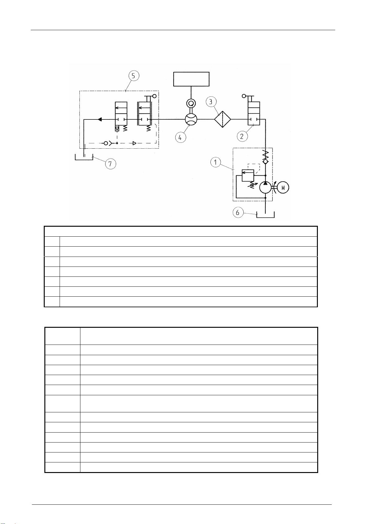
4.3. Hydraulic system of V-line AdBlue®47xx.xxx dispenser
Figure. 1 –Hydraulic scheme of V-line AdBlue®47xx.xxx dispenser
Legend
1
Submersible pump
2
Closing valve
3
Filter
4
Electronic meter ADAST M 403.25 EAP/1 + el. counter ADP1/L, ADP1/T, ADP2/T
5
Delivery nozzle
6
Storage tank of AdBlue®
7
Vehicle tank
Hydraulic system of the V-line R AdBlue®47xx.xxx dispenser consisting of components (Figure 2):
Position
number
Components of AdBlue®hydraulic system of the AdBlue®dispenser
1
Ball valve G 1“
2
Drain ball valve
3
Filter AdBlue®
4
Connecting pipe between the filter and meter
5
Meter flange
6
Four-piston all-aluminium AdBlue® meter with integrated magnetic pulse
transmitter ADAST M 403.25EAP/1
7
Magnetic pulse transmitter METRA MTX 076 or ADAST41
8
Valve flange
9
AdBlue®electromagnetic valve
10
Hose adaptor DN 16
11
Hose DN 16 to the nozzle
12
Heating of hydraulic housing

USER’S MANUAL V-line AdBlue®47xx.xxx
7
Figure. 2
USER’S MANUAL V-line AdBlue®47xx.xxx
8
V-line AdBlue®47xx.xxx series dispensers (pressure design) differ from suction dispensers because they
are not equipped with the pumping monoblock. A safety breaking valve shall be fitted in the connection.
The valve prevents AdBlue®leakage in case of the dispenser damage. This valve is not a part of the
dispenser, as well as the pump, which is located in the underground tank. The pressure dispensers are
equipped with an inlet spherical valve for closing the AdBlue®input in case of repairs.
The pumped AdBlue®is supplied from the central submerged pump located directly in the fuel storage tank
through the safety breaking valve, spherical check valve and the filter with filtering property of 60 µm.
Liquid is discharged from the filter through the meter and the electromagnetic valve to the dispensing hose
with the dispensing nozzle at its end. The dispensing nozzle lever controls the rate of flow.
The pressure system of the distribution should be designed with a submerged pump built-in directly into the
storage tank under the substance level. The tank should be equipped with a detector of the lowest
substance level switching the el. circuit of the pump motor being the min. level attained.
The location of the pump under the lowest fluid level in the storage tank and the min. level control switch
shall prevent the access of air or gas into the pump.
P12 = 0 parameter shall be preselected in the electronic counter for the pressure system of submerged
pumps operation in the storage tank in case of V-line AdBlue®47xx.xxx dispensers operation. At first the
electronic counter starts up the submerged pump in this mode of operation (the fluid in entire hydraulic
system is under pressure) then the counter tests the displays and closes the el. magnetic valve - and the
dispensing is started. Applying these conditions is the requirement 5.1.3 OIML R 117-1 2007 (E).
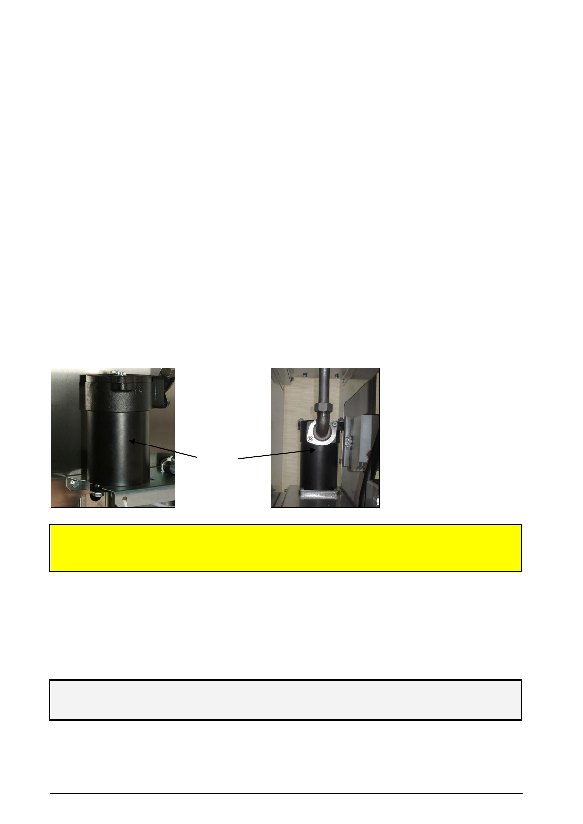
4.3.1 Filter
Whole metalic filter (pos.3) is connected by connection (pos. 4) to inlet of the meter (pos. 4) –to meter
flange (pos. 5) and closing stainless baal valve (pos. 1).
Filter is equipped by stainless filter insert with filtration ability 60 µm.
ATTENTION!
Filter is designed as meter protection from mechanical damage contained imide of dispensed
medium AdBlue®. Purity of dispensed medium AdBlue®must be guaranted by medium subsupplier
and permanent clean policy of storage space inside of storage container.
4.3.2 Piston flow meter
Measuring unit consists from four piston unit and integrated magnetic encoder. Measuring unit is measuring
in flow rate range 4 - 40 dm3.min-1 and operational temperatures of measured medium - 10 až +30 °C and
ambient temperature -40°C to +55 °C for nominal pressure up to 0,32 MPa.
Encoder is reading spins of magnet disc connected to central shaft and transfering the spins to electronic
signal.
Meters are supplied with optional integrated magnetic pulse transmitter METRA MTX 076
or ADAST 41 - M 403.25AP/1, M 403.32EAP/1.
Meters with the designation of EP in electronic calibration, indicating P mechanical calibration.
Filter

USER’S MANUAL V-line AdBlue®47xx.xxx
9
4.3.3 Electromagnetic(solenoid) valve
Electromagnetic valve is placed on meter output. Valve control is provided by electronic counter. Body of
the valve is nicle plated, pistons and bushes are finished from material on teflon basis.
Electromagnetic valve is supplied as option upon costumer request.
4.3.4 Delivery hose AdBlue®
Delivery hose AdBlue®is finished from speciall rubber designed for AdBlue®. Delivery hose is placed on hose
reel and ended by delivery nozzle.
4.3.5 Delivery nozzle AdBlue®
Speciall finishing of components delivery nozzle ELAFLEX AdBlue®made from materials resistent to
medium AdBlue®. The nozzle is equiped by automatic closing valve, function STOP system preventing tank
overfilling and by swivel.
Inside of nozzle spout is build in magnetic valve.The dispensing is possible only if the defined magnetic
zone in filling inlet of vehicle tank will open magnetic svitch in spout of delivery nozzle. By this safety
fiction is eliminated to fill different fuel tank by product AdBlue®. Delivery nozzle is hanged in speciall
vertical cover imide of external module of AdBlue® dispenser. Nozzle space is covered by front doors a in
temperature fall down is heated.
The nozzle with covering doors can be locked if the station is in off mode.
4.3.6 Connection elements
Connections of hydraulic system of container filling station is made by connecting pipes and fittings made
from speciall stainless steels and speciall ruber hose resistent to AdBlue®.
Baal valve G 1“
4.4. Electronics
The dispenser control shall meet the exacting requirements of simplicity and convenience and depends on
the hanging up and lifting of the dispensing nozzle.
ADPMPD/T, ADPMPD/T-PWM, ADP1/T, ADP2/T, ADP1/L electronic counter of an up-to-date design with
central processor board equipped with a high efficient microprocessor. The configuration of the counter
and its modes of operation are adjusted by more than seventy parameters. The counter is provided with a
self-diagnostic system. The counter outlets control the motors, valves, signalling circuits and vapours
exhaustion. The electronic counter processes the impulses coming from the impulse sensor and transmits
them to the display, which displays the dispensed volume, its price and a price per a volume unit. In case
of power failure or voltage drop the data displayed on the LCD remain for 30minutes at least.
Counters ADPMPD/T, ADP1/T, ADP2/T, ADP1/L are standardly equipped for electronic meter calibration
(Electronic Calibration of Meters –EC) and per request by ATC –(Automatic Temperature
Compensation).
Electronic Calibration of Meters (EC) enable to correct measured volume by designed declination in
operation range -5,00 % to +5,00 % of recognised meter non accurancy by step of 0,05 %.
Baal valve G 1“
Filter flange
Connecting pipe
between the
filter and meter

USER’S MANUAL V-line AdBlue®47xx.xxx
10
Providing of calibration is allowed to authorised person, only. The DIP calibration switches must be fixed by
plomb after calibration finish.
Displays: LCD type with BACK LIGHT illumination
LCD displays with BACK LIGHT DISPLAY (BLD) illumination are used especially for their good readability.
The duration of data holding on the display after supply voltage failure is 30 minutes at least. Decimal point
on BLD display devices is represented automatically in accordance with the setting of parameters.
Lighting
LED diodes are used for the illumination of displays at dispensers.
ON / OFF switching of the illumination is automatically carried out with the activation of electronics.
Totalizer: non-resettable electronic counter of dispensed volume and its price –11 digits –or non-
resettable electromechanical counter of dispensed volume –7 digits.
Electronic counter of ADPMPD/T, ADPMPD/T-PWM, ADP1/T, ADP2/T, ADP1/L series operates with a 2-
channel impulse generator producing 2x 100 impulses per 1 dm3. The HW and SW counters of the
ADPMPD/T, ADP1/T, ADP2/T, ADP1/L series enable high metering accuracy and the application of the
electronic calibration using the 2-channel impulse generator.
IMPORTANT NOTICE:
Connection of the magnetic pulse transmitter ME 01-05, ME 01-05-05, MTX 076 and ADAST 41 to the
electronic counter ADP1/L (connector X1), electronic counter ADP1/T, ADP2/T (connector X2) and
electronic counter ADPMPDx/T, ADPMPDx/T-PWM (connector X3) - see enclosure 8, 9, 10.
The local electronic preselection system in IP67 design is integrated into the counter case. The
preselection enables the Customer’s preselection of the exact volume or the price of the product to be
dispensed. The two-stage or proportional electromagnetic valves ensure the closing of flow and exact
dispensing of the preselected volume / price and smooth initiation of dispensing.
The fuel dispensers can be equipped with ADAMAT filling automatic equipment. This equipment enables
dispensing and payment of the product by means of contactless, magnetic and chip cards including receipt
printing. This equipment undertakes simultaneously all functions of the dispenser electronic counter for
non-public and public dispensing. The electronics of the filling automatic equipment can be complemented
by the ADPMPD/T, ADPMPD/T-PWM, ADP1/T, ADP2/T, ADP1/L electronic counter with public dispensing.
The fuel dispenser is connected through a communication line to the control system, which controls the
operation of the whole filling station (releasing of dispensers, volume preselection, unit price variation,
self-diagnosis, etc.). The dispensers can be operated even at the filling stations without any control system
–i.e. in serviced operation.
Circuit diagrams for the connection of individual dispenser types to the switchboard of the filling station –
see enclosures.
4.4.1 Communication to the control system
The ADP1/T, ADP2/T, ADP1/calculator can operate independently and/or can be controlled by a site
control system.
The calculator is connected to the site control system via the RS-485 line, which is controlled by its own
communication protocol EASY-CALL, and /or according to IFSF standards (communication level LON or
TCP/IP- Ethernet).
Communication to different control systems shall be consulted with the manufacturer of the dispensers
in advance.
The fuel dispensers connected to the control system can be operated in the mode of volume preselection or
the financial sum preselection from the control system (the dispensers have to be equipped with two-
stage or proportional electromagnetic valves).
4.5. Signalling of dispenser conditions (SO)
On Client’s special requirement the fuel dispenser can be equipped with a red signal light, which gives
information to the customer and the operator about the present dispenser condition –the dispenser is
blocked or ready for fuel filling.

USER’S MANUAL V-line AdBlue®47xx.xxx
11
4.6. SOPA design
On Client’s special request the dispenser in service mode can be equipped with magnetic release switch
(SOPA design). The operator of the filling station can release the dispenser for single filling operation in this
mode. After nozzle lifting the displays are reset and fuel filling is started.
After hanging up the nozzle, the dispensed volume and quantity values are permanently displayed until the
dispenser is magnetic released and the dispensing nozzle is lifted off subsequently. The red signal light
informs both the operator and the customer about the condition of the dispenser.
4.7. Design with heating of the electronic case
On the special customer´s requirement the fuel dispenser can be delivered with heating of electronic case
by heater 250 W. For feeding of the heating is used an individual cable.
4.8. Heating of hydraulic housing
In the closet hydraulically dispenser is built powerful fan heater with thermostat - power 950 W. Protects
interior hydraulic hose module and the module against condensation and thermal protection components of
the hydraulic system of the dispenser against crystallization and AdBlue®freezes when temperatures drop
below freezing.
5. TECHNICAL DATA
Electronic counter
ADPMPD/T, ADP1/T, ADP2/T, ADP1/L
Tankautomat (CRID)
ADAMAT/PNN, ADAMAT/PNA, ADAMAT/EMV
Display
Iluminated LCD - BACK LIGHT DISPLAY (BLD)
ADAMAT - Graphic BLD, Touch screen
Connecting piece –pressure system
DN 25 with external screw G 1“
Minimum innner diameter required
DN 16 (stainless pipe or special rubber hose for AdBlue®)
Alternative DN 19 –rubber hose for AdBlue®
Measured fluid
AUS 32 ISO 22241 (AdBlue®)
Accuracy of measurement
± 0,5 %
Max. operating pressure pmax
0,32 MPa
Min. operating pressure pmin
0,12 MPa
Max. flow rate Qmax
40 dm3.min-1
20 dm3.min-1
10 dm3.min-1
Min. flow rate Qmin
4 dm3.min-1
2 dm3.min-1
2 dm3.min-1
Min. measured quantity (MMQ)
2 dm3
2 dm3
2 dm3
Maximum flow rate when dispensing from one
nozzle Qmax
40 ±4 dm3.min-1 (for dispenser 4701.xx0/40)
20 ±2 dm3.min-1 (for dispenser 4701.xx0/20)
10 ±1 dm3.min-1 (for dispenser 4701.xx0/10)
Maximum flow rate when dispensing from both
nozzless simultaneously Qmax
30 ±3/30 ±3 dm3.min-1 (for dispenser 4701.20x/40/40)
30 ±3/5 ±1 dm3.min-1 (for dispenser 4701.11x/40/10)
15 ±2/5 ±1 dm3.min-1 (for dispenser 4701.11x/20/10)
5 ±1/5 ±1 dm3.min-1 (for dispenser 4701.02x/10/10)
Ambient operating temperature
-40 °C to +55 °C
Medium temperature
-10 °C to +50 °C
Filtration ability
Standard 60 µm
Reach of dispensing hose
4,5 m (V-line R)
Max. level of noise
<60 dB
Power supply of electronics
Unap
Pnap
1/N/PE AC 230 V ±15 % 50 Hz
input 85 VA
Power supply of ADAMAT
electronics
Unap
Pnap
1/N/PE AC 230 V ±15 % 50 Hz
input 120 VA
Power supply of electronic case
heating
Unap
Pnap
1/N/PE AC 230 V ± 15 %, 50 Hz
input 250 VA

USER’S MANUAL V-line AdBlue®47xx.xxx
12
Power supply of hydraulic case
heating
Unap
Pnap
1/N/PE AC 230 V ± 15 %, 50 Hz
input 950 VA
Basic sensed unit
0,01 dm3
Number of impulses per 1 dm3
100
Permissible deviation of sensed volume
+/-1 impulse, i.e. 0,01 dm3
Price displayed
6 digits with the setting of digit position
Volume displayed
6 digits with the setting of digit position
Unit price displayed
4 digits with the setting of digit position
Total volume counter
electromechanical - 7 digits
electronically - 11 digits
Communication interface
RS 485; EASY CALL
Pumalan extended
FULL DART
NARA standard
RS 485; IFSF –LON, TCP/IP (Ethernet)
Average operating period of a repair
too = 25 minutes
Average service life
tz= 5 years
6. MARKING
All manufactured and delivered dispensers are provided with a rating plate, which includes the following
data and is located on a visible point of the dispenser body:
1.
Measuring device manufacturer and address
Adast Systems, a.s., CZ –679 04 ADAMOV 496
2.
Name of measuring device
AdBlue®dispenser
3.
The „CE“ marking and supplementary
metrology marking
4.
Type
See enclosure No 16 and 17
5.
Number of EC –type examination certificate
TCM 141/07 –4518
6.
Accuracy class
0,5
7.
Serial number and year of manufacture
According to dispensers manufacturer files
8.
Liquid temperature range –TLiq [°C]
-10 to +50
9.
Ambient temperature range –TAmb [°C]
-40 to +55
10.
Mechanical class
M 2
11.
Electromagnetic class
E 2
12.
Liquid
AdBlue®
13.
Minimum measured quantity (MMQ) [L]
2
14.
Maximum flowrate Qmax [L/min]
40
15.
Minimum flowrate Qmin [L/min]
4
16.
Maximum pressure pmax [bar]
3,2
7. INSTALLATION
7.1. Hydraulic part
ATTENTION!
THE DISPENSER INSTALLATION CAN BE CARRY OUT ONLY BY THE ORGANISATION AUTHORISED BY
MANUFACTURER.
Read carefully the article 1. IMPORTANT NOTICE.

USER’S MANUAL V-line AdBlue®47xx.xxx
13
The AdBlue®dispenser can be joined only to process equipment (tanks, piping) of perfect tightness and
cleanness. The supplier of the process equipment is responsible for its tightness and cleanness.
Prior to the installation the organisation shall perform the inspection of used power and communication
cables.
The dispenser is mounted to the base frame M12 × 70 bolts through special pads (pads are supplied
dispenser).
When the AdBlue®dispenser is installed, they shall check the tightness, function of hydraulic equipment of
the dispenser, supply piping and fittings. They also check power and communication cables including their
lines and fixing.
Prior to official metrological testing the dispenser (every dispensing nozzle) has to operate for min. 5
minutes in max. flow rate
The process and service equipment of filling stations can be operated only when they have been built
up according to the approved design and on the basis of positive result of licence regime.
7.2. Wiring
ATTENTION!
For safety operation must be used electrical connection of AdBlue® dispenser from switchboard with
oveload protection and for parameters 230 V / 50 Hz / Power supply of electronics and heating –see
article 5 - TECHNICAL DATA
Earthing conductor shall be connected to the shaft under every dispenser.
Leads to the AdBlue®dispenser must be sealed to prevent its interior from the penetration of liquids
(AdBlue®) or vapours. Only cable terminals resistant to AdBlue®effect can be used in the shafts under
dispensers. The cable bushings can always be used for one cable only.
ATTENTION!
Emergency switching off: It shall be enabled to switch off the filling equipment from one point, which
is accessible anytime. The electric equipment situated in the explosion hazard area can be switched
off by means of the emergency breaker located outside the explosion hazard area. The switch for
normal operation can be also used as emergency breaker.
Supply conductors are connected to the junction box located in the dispenser.
The communication line cable is connected to the junction box for the communication line.
There are two wiring systems of the filling station: either the communication line is connected to the
dispenser (i.e. self-service operation with the control system) or not (i.e. service operation).
The dispenser in self-service operation with the control system is connected through the communication
line to the control system which controls operation of complete filling station (i.e. dispenser release,
preselection of volume and price, unit price alteration, selfdiagnostics, etc.).
8. PUTING INTO OPERATION
ATTENTION!
Before start must be made revision of wiring. Also is recomended to heat imide container space to
minimum temperature 5 °C (start the heater if needed).
8.1. Puting of the AdBlue® dispenser to operation mode
Hang up the delivery nozzle.
Switch on the power supply in main board of filling station (electronics supply in winter and heating).
By hang out of delivery nozzle will be made display test (test of eights), when the eights will be
zerowed the delivery can be started.
Place the nozzle in.
In case of turn on of DU with hang out nozzle must bet he nozzle hunged in and hanged out again, to
activate DU (reset display).
After this is possible to provide delivery of AdBlue®.

USER’S MANUAL V-line AdBlue®47xx.xxx
14
8.2. Puting of AdBlue® dispenser to OFF mode
Switch off power feed in filling station main terminal.
8.3. New reseting of AdBlue® dispenser into operation after power supply failure
After power supply failure or voltage fluctuation will stay data on display about the price and volume
of last provided transaction since interval of last time of nozzle hang out.
In case if power supply happened during of medium tanking , the nozzle has to be hang in (on the
display will stay value of the volume and price) and cash in the amount shown on the display.
By renewing of power supply is the electronic counter in operation mode and another delivery can be
made by hang out of the delivery nozzle.
ATTENTION!
After puting into operational mode in expected low temperature period (Tamb.) under 0 °C, the
rating must be turned ON permanatly. This is obligation even in „Out of order“ mode.
Termostat of heater to be set on value +5 °C!!
9. OPERATION
By hang out of delivery nozzle the connecting switch controlled by magnet placed in nozzle boot will start
the electronic couter of AdBlue® dispenser, will be made reset of the display after it the connecting of
pump elektromotor and mening of electromagnetical valve placed in hydraulic vave of AdBlue® dispenser (if
installed).
By AdBlue® dispenser for pressurre sytem will be switched in of pump elektromotor placed in container tank
imediatelly after hang out of the nozzle (before providing of test and display reset). Electromagnetic valve
is open after providing of test and display reset.
After placing of delivery nozzle spout to the vehicle tank and push of nozzle lever the tanking is started
(medium delivery). The vehicle tank must be equipped by magnetic adaptor (like ELAFIX 40) to allow the
spout open.
Delivery speed is controlled by nozzle lever (pus hor repase). When the dispensing is finished, the nozzle is
placed out from vehicle tank input and placed to the nozzle boot of DU will be by magnetic switch to
dissconection of power feed to submersible pump.
The records of last dispensing will stay displayed untill next one delivery.
The delivery nozzle is controlled as per instructions shown in enclosure no. 4 of this manual.
10. FUNTION OF MANAGER AND SERVICE KEYBOARD
The KL-MANINF (as pic. 4)manager keyboard and the KL-SERINF (as pic. 5)service keyboard are delivered
as a design with infrared wireless transmission IR. These device are delivered as option.
IR KL-MANINF manager keyboard
The keyboard enables the setting of unit prices and the situation display of electronic totalizers.
The manager keyboard is equipped with four keys marked „0“, „+“, „–“ and „R“. The „0“ key is used for
the transition to the "setting of unit prices for MAN" and for the termination of any function executed on
the manager keyboard.
The „+“ and „–“ keys are used for proper setting of the unit price values or for the transition to the mode
of "situation display of electronic totalizers".
The „R“ key is used for check of vapour recovery exhaustion.
IR KL-SERINF service keyboard
The keyboard enables the counter setting and the keying of values for electronic calibration of meters and
ATC, the situation display of electronic totalizers, setting of unit prices and setting the vapour exhaust
recovery.
The service keyboard is fitted with four keys, „0“, „+“„–“ as a standard and the "S" key as an extra key.
The "S" key is used for the transition to the mode of "the data setting / calibration".
If the "S" key is not used, the service keyboard can be used for all functions controlled by the manager
keyboard and the keying is identical with that of the manager keyboard.

USER’S MANUAL V-line AdBlue®47xx.xxx
15
Note
If the nozzle has been lifted at least once since the last activation of the counter, the transition to the
setting of unit prices is not executed in the MAN mode. The transition to the setting is also not executed
even in case the nozzle has been either hung up again without fuel dispensing or previous transaction has
not been deactivated by means of RLS entry.
10.1 Manual setting of unit prices
Necessary conditions for the transition to the setting of unit prices
–MAN mode of operation
–the nozzle has not been lifted since the last activation of the counter
–transaction executed shall be acknowledged (deactivation by means of RLS entries).
In the MAN mode the unit prices of fuel product are set by means of the KL-MANINF manager keyboard or
the KL-SERINF service keyboard.
1. The user can enter the setting mode of unit prices by depressing the „0“ key.
2. In the setting mode of unit prices
–the number of side for which the unit price is being set ("1" ... A side, "2" ... B side) is displayed on
the first line of displays (i.e. on the line of total price)
–the number of nozzle for which the unit price is being set is displayed on the second line of displays
(i.e. the line of total volume)
–on the third line of displays the digit, the value of which is being set by the user, is flashing (e.g. on
the line of unit price)
3. The user
–raises the numerical value of the digit actually set (i.e. the flashing one), (digit 9 passes into 0), by
depressing the "+" key we can list through 0-9 values - i.e. the autorepeat function
–shifts the digit setting to higher digit positions by means of the "–" key
shifts the setting from the highest position of the product unit price to the lowest digit position of
the product unit price of the next nozzle by means of the "–" key
4. In this way the user can set successively the price values for all nozzles on the A side, then B side (if it
exists and the products on this side differ in price).
5. Whenever the user can terminate the setting of the unit price values by depressing the „0“ key.
6. Now the unit price values have been written in non-volatile storage in this way and the counter sets the
MAN mode.

USER’S MANUAL V-line AdBlue®47xx.xxx
16
10.2 Setting of unit price values from the control system in AUTO mode
In AUTO mode the unit price values are set from the control system for all transactions independently on
unit price values set for the MAN mode.
The unit price values for the AUTO mode are set for all dispensing points by dynamic statement (command)
"permission to dispense" transmitted from the filling station console or by the "price setting" statement. All
these statements are a part of the specification of the EASYCALL communication protocol.
10.3 Display of electronic totalizers
The ADPMPD/T, ADP 1,2/Tcounter is fitted with non-resettle electronic totalizers of volume and price for
individual dispensing nozzles.
The totalizers can be displayed on the displays of the side by means of the KL-MANINF manager keyboard or
the KL-SERINF service keyboard. The display of the totalizer can be switched by lifting the relevant nozzle.
The sum of the volume (or the sum of the price) is displayed on the displays of the side on the coupled lines
of the total price and total volume.
Both displays of the side display an identical sum.
As the first from the left "U" character is displayed on the total price line for the display of the volume
sum and "A" character for the display of the price sum.
The second character from the left displays the highest digit position of the relevant sum.
The sixth character from the left displays the lowest digit position of the relevant sum.
The sums are counted and displayed with decimal place count according to the data setting of the counter.
The side number and the nozzle number of the totalizer displayed at this moment are displayed on the unit
price line:
e.g..: 1 - 3...A side - nozzle No. 3;
2 - 1...B side - nozzle No. 1.
Display procedure:
1. Both dispensing points shall be free (transitions are not running at any of the both points and
terminated transactions shall be acknowledged).
2. Depress the "+" key to display the volume sum. Depress the "–" key to display the price sum.
3. All segments light up and light out on the displays of the sides after depressing the "+" key (or the "–"
key) (similarly with the transaction starting to checking if all segments display correctly) and total
number of feeding voltage drop-outs is shortly displaced.
4. Then "U" and the volume sum of the relevant nozzle (or "A" and the price sum of the relevant nozzle)
are displayed on the displays of sides.
5. It is possible to carry out the transition to the volume totalizer displays of the next dispensing nozzles
by repeated depressing the "+" key or by lifting the relevant nozzle (as well as the transition to the
price totalizer displays of the next dispensing nozzles by repeated depressing the "–" key or by lifting
the relevant nozzle).
6. Terminate the scanning of electronic totalizers by depressing the "0" key and in case the thermal and
electronic calibration are activated, transition in the display mode of their setting occurs.
7. The setting of thermal calibration for relevant nozzle is activated by the ATC text. The setting of
electronic calibration of the relevant nozzle counter is activated by the EC text.
8. Terminate the scanning by depressing the "0" key and return to the standard mode.
Unit price seting
Shift from most significent
digit, side A , nozzle 1
Shift from most significent
digit, side B , nozzle 1
This manual suits for next models
5
Table of contents
Other Adast Systems Dispenser manuals


