NCR Retrofit OPTIC 5 Touch User manual

Retrofit OPTIC 5 Touch + InvencoLink Wayne
Ovation (US & Canada) Installation Guide
Kit Number: 6005-0005-8801
B005-0000-2511
497-0522366
Issue A

Document Number
DCV-00545
Date Released
Jul. 2020
Revision Number/Security level
R01 S2
Retrofit OPTIC 5 Touch + InvencoLink Wayne Ovation (US & Canada)
Installation Guide
Retrofit OPTIC 5 Touch +
InvencoLink Wayne
Ovation (US & Canada)
Installation Guide
Kit Part Number: 6005-0005-8801

2
Document Number
DCV-00545
Date Released
Jul. 2020
Revision Number/Security level
R01 S2
Retrofit OPTIC 5 Touch+ InvencoLink Wayne Ovation (US & Canada)
Installation Guide
Release History
Version
Prepared by
Date
Change description
0
Michael Doh
09-Jul-20
Based on DCV-00450 R04; initial
version for UL approval
1
Michael Doh
30-Jul-20
Corrected Invenco Link reference
document number
© 2020 by Invenco Group Limited
All rights reserved
No part of this document may be copied or reproduced in any form without prior written consent from Invenco.
Invenco has taken great effort to verify the accuracy of this document but assumes no responsibility for any technical
inaccuracies or typographical errors

3
Document Number
DCV-00545
Date Released
Jul. 2020
Revision Number/Security level
R01 S2
Retrofit OPTIC 5 Touch+ InvencoLink Wayne Ovation (US & Canada)
Installation Guide
Contents
Release History.....................................................................................................................2
1 Introduction....................................................................................................................4
1.1 Tools Required .......................................................................................................4
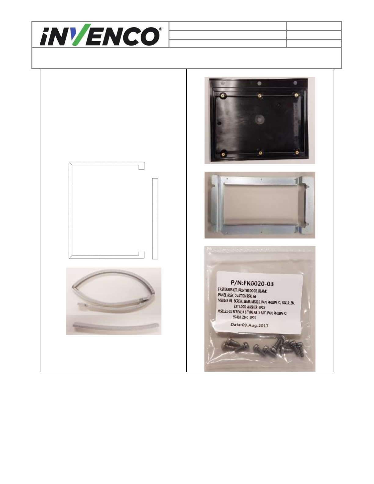
1.2 Installation Kit Contents ..........................................................................................5
2 Safety & Compliance Information...................................................................................9
2.1 Preliminary Precautions..........................................................................................9
2.2 Emergency Total Electrical Shut-Off.......................................................................9
2.3 Total Electrical Shut-Off Before Access ..................................................................9
2.4 Evacuation, Barricading and Shut-Off.....................................................................9
2.5 Read the Manual ....................................................................................................9
2.6 Follow the Regulations..........................................................................................10
2.7 Replacement Parts ...............................................................................................10
3 Safety Symbols and Terminology.................................................................................10
3.1 Prevent Explosions and Fires ...............................................................................10
3.1.1 No Open Flames............................................................................................11
3.1.2 No Sparks - No Smoking ...............................................................................11
3.1.3 Working Alone ...............................................................................................11
3.1.4 Working with Electricity Safety.......................................................................11
3.1.5 Hazardous Materials......................................................................................11
3.1.6 In an Emergency............................................................................................11
3.1.7 Approvals.......................................................................................................12
3.1.8 Laser Warning ..................................................Error! Bookmark not defined.
3.2 Computer Programs and Documentation..............................................................12
4 Installation Guide.........................................................................................................13
4.1 Disassembly Procedure........................................................................................13
4.2 Pre-Installation Procedure.....................................................................................31
4.2.1 Replace the RFK Panel Gasket .....................................................................31
4.2.2 Install the InvencoLink Converter...................................................................34
4.3 Installation Procedure...........................................................................................35
4.3.1 Wiring Completion .........................................................................................46
5 First Power-Up.............................................................................................................47

4
Document Number
DCV-00545
Date Released
Jul. 2020
Revision Number/Security level
R01 S2
Retrofit OPTIC 5 Touch+ InvencoLink Wayne Ovation (US & Canada)
Installation Guide
1 Introduction
The documentation provides some basic guidelines for installing the OPTIC 5 Touch Outdoor Payment
Terminal (OPT) system.
This Retro-Fit Kit can be installed into either Side A or Side B of a Wayne Ovation dispenser;
•For a single-sided installation, or if this Kit will be installed into Side A (i.e. the first side
installed) of a double-sided installation, it requires the pre-installation of UL Listed by Report
Retrofit Kit Part Number 6009-0008-8801 (InvencoLink Converter) before installation into the
dispenser. The process is covered in §4.2 Pre-Installation Procedure of this instruction, by reference
to the instructions in that Kit.
•For a double-sided installation, two of these Kits are required.
1.1 Tools Required
The following tools are required to mount the OPTIC 5 Touch OPT:
•Torx T25 security screwdriver
•Philips #1 screwdriver
•Philips #1 screwdriver with >5” shaft
•Philips #2 screw driver
•Flat 5mm screwdriver
•Small adjustable spanner
•Side cutters
•Cable (zip) ties
•Pliers
•¼” Socket or Nut Driver
•9/32” Socket or Nut Driver
•Small flat blade scraper or putty
knife.
•Towelling cleaning rags.
•Household sticky residue remover
containing limonene.
e.g. Goo Gone®
•100% Isopropyl Alcohol (IPA)
cleaner.
WARNING
Do NOT use power tools if working on a fuel station forecourt.
Any spark could cause an explosion.

5
Document Number
DCV-00545
Date Released
Jul. 2020
Revision Number/Security level
R01 S2
Retrofit OPTIC 5 Touch+ InvencoLink Wayne Ovation (US & Canada)
Installation Guide
1.2 Installation Kit Contents
Unpack the Ovation Retro-Fit Kit (6005-0005-8801) and check that all of the parts listed below are
present.
Display RFK Panel with pre-installed
OPTIC 5 Touch OPT (RP00020-XX):
PSU plate with cables (EZ0632):

6
Document Number
DCV-00545
Date Released
Jul. 2020
Revision Number/Security level
R01 S2
Retrofit OPTIC 5 Touch+ InvencoLink Wayne Ovation (US & Canada)
Installation Guide
Display RFK Gasket (MP0526):
Isolating Cover with captive screws (MZ0116):

7
Document Number
DCV-00545
Date Released
Jul. 2020
Revision Number/Security level
R01 S2
Retrofit OPTIC 5 Touch+ InvencoLink Wayne Ovation (US & Canada)
Installation Guide
Printer blank panel assembly (IA0044):
Consisting of:
MZ0109 Printer blank panel (right top)
MP0618 Printer blank panel clamp (right mid)
MP0620 Printer blank panel gasket A (below left)
MP0621 Printer blank panel gasket B (below right)
FK0020 Printer blank panel fastener kit (right
bottom) consisting of:
•6 x MS0148: M3x10 Philips #1 screw
•4 x MS0121: #6 Type AB, X 3/8” Philips #2
screw

8
Document Number
DCV-00545
Date Released
Jul. 2020
Revision Number/Security level
R01 S2
Retrofit OPTIC 5 Touch+ InvencoLink Wayne Ovation (US & Canada)
Installation Guide
UPC blank panel assembly (IA0045):
Consisting of:
MZ0103 UPC blank panel (right)
MP0527 UPC blank panel gasket (right)
FK0019 UPC blank panel fastener kit (below)
consisting of:
•4 x MS0148: M3x10 Philips #1 screw
Sundry Parts & Cables:
EK0131
Cat-5e, Flexible 2.5m, YELLOW
EK0130
Ground Cable 8G fork to ¼” QC
female 2m
EK0137
Wayne Pump to PSU Adaptor
EK0127
Wayne Pump to InvencoLink
Fastener Kit RFK (FK0016)
8
MN0043 M3X15 SEMS Stand Off (right)
2
MN0029 NUT, 8-32 UNC,11/32" AF, ZINC

9
Document Number
DCV-00545
Date Released
Jul. 2020
Revision Number/Security level
R01 S2
Retrofit OPTIC 5 Touch+ InvencoLink Wayne Ovation (US & Canada)
Installation Guide
2 Safety & Compliance Information
This section introduces the hazards and safety precautions associated with installing, inspecting,
maintaining or servicing the OPTIC 5 Touch OPT. Before proceeding, check the relevant hazard and
safety information. Fire, explosion or electrical shock could occur and cause death or serious injury if
these safe service procedures are not followed.
2.1 Preliminary Precautions
You are working in a potentially dangerous environment of flammable fuels, vapor, and high voltage. Only
trained or authorized individuals knowledgeable in the related procedures should install, inspect,
maintain or service this equipment.
2.2 Emergency Total Electrical Shut-Off
Locate the forecourt emergency fuel shut-off valves and electrical isolation breakers. Understand how to
use these, should they be required. Locate the switch or circuit breakers that shut-off all power to all
fueling equipment and dispensing devices.
2.3 Total Electrical Shut-Off Before Access
Any procedure requiring access to electrical components or the electronics of a pump/dispenser requires
total electrical shut-off of that unit. Understand the function and location of this switch or circuit breaker
before inspecting, installing, maintaining, or servicing the OPTIC 5 Touch OPT.
2.4 Evacuation, Barricading and Shut-Off
Any procedures requiring accessing a pump/dispenser head requires the following three actions:
•An evacuation of all unauthorized persons and vehicles
•Using safety tape or cones as barricades to the effected units
•A total electrical shut-off of the affected unit(s)
2.5 Read the Manual
Read, understand and follow this manual and any other labels or related materials supplied with the
equipment. If you do not understand a procedure, call an Invenco Authorized Service Centre or Invenco
Service Officer. It is imperative to your safety and the safety of others to understand the procedures
before beginning work.

10
Document Number
DCV-00545
Date Released
Jul. 2020
Revision Number/Security level
R01 S2
Retrofit OPTIC 5 Touch+ InvencoLink Wayne Ovation (US & Canada)
Installation Guide
2.6 Follow the Regulations
Regulations in OSHR (Occupational Safety and Health Regulations), national, state and local codes,
including customer requirements must be followed. Failure to install, inspect, maintain or service this
equipment in accordance with these codes, regulations and standards may lead to legal citations with
penalties and may affect the safe use and operation of the equipment.
2.7 Replacement Parts
Use only genuine Invenco replacement parts and retrofit kits on your installation. Using parts other than
genuine Invenco replacement parts could create a safety hazard and violate local regulations.
3 Safety Symbols and Terminology
This safety alert symbol is used in this manual and on warning labels to alert you to a precaution
which must be followed to prevent potential personal safety hazard. Obey safety directives that
follow this symbol to avoid possible injury or death.
Signal Words
These signal words used in this manual and on warning labels tell you the seriousness of particular safety
hazards. The precautions below must be followed to prevent death, injury or damage to the equipment:
DANGER: Alerts you to a hazard or unsafe practice which will result in death or
serious injury.
WARNING: Alerts you to a hazard or unsafe practice that could result in death or
serious injury.
CAUTION: Designates a hazard or unsafe practice which may result in minor
injury, property or equipment damage.
Working With Fuels and Electrical Energy
3.1 Prevent Explosions and Fires
Fuels and their vapors may explode or burn if ignited. Spilled or leaking fuels cause vapors. Even filling
customer tanks will cause potentially explosive vapors in the vicinity of the dispenser or island.

11
Document Number
DCV-00545
Date Released
Jul. 2020
Revision Number/Security level
R01 S2
Retrofit OPTIC 5 Touch+ InvencoLink Wayne Ovation (US & Canada)
Installation Guide
3.1.1 No Open Flames
Open flames from matches, lighters, welding torches or other sources can ignite fuels and
their vapors.
3.1.2 No Sparks - No Smoking
Sparks from starting vehicles, starting or using power tools, burning cigarettes, cigars or
pipes can also ignite fuels and their vapor. Static electricity, including an electrostatic
charge on your body, can cause a spark sufficient to ignite fuels and their vapors. After
getting out of a vehicle, touch the metal of your vehicle to discharge any electrostatic
charge before you approach the dispenser island.
3.1.3 Working Alone
It is highly recommended that someone who is capable of rendering first aid be present during servicing.
Be familiar with Cardiopulmonary Resuscitation (CPR) methods if you are working with or around high
voltages. This information is available from the First Aid training providers. Always advise the station
personnel about where you will be working, and caution them not to activate power while you are working
on the equipment. Use the OSHA Tag-out/Lockout procedures. If you are not familiar with this
requirement, refer to information in the relevant manual and OSHA documentation.
3.1.4 Working with Electricity Safety
Ensure that you use safe and established practices in working with electrical devices. Poorly wired
devices may cause a fire, explosion or electrical shock. Ensure that grounding connections are properly
made. Take care that sealing devices and compounds are in place. Ensure that you do not pinch wires
when replacing covers. Follow OSHA Tag-out/Lockout requirements. Station employees and service
contractors need to understand and comply with this program completely to ensure safety while
equipment is down.
For US: Follow all applicable requirements in NFPA 30, 30A and 70, and those of the Local Authority
Having Jurisdiction for electrical wiring.
For Canada: Follow all applicable requirements in Canadian Electrical Code (CE Code), CSA C22.1.
3.1.5 Hazardous Materials
Some materials present inside electronic enclosures may present a health hazard if not handled correctly.
Be sure to clean hands after handling equipment. Do not place any equipment in mouth.
3.1.6 In an Emergency
Compile the following information in case of emergency:
•Location of accident (e.g. address, front/back of building, etc).
•Nature of accident (e.g. possible heart attack, struck by a vehicle, burns, etc).

12
Document Number
DCV-00545
Date Released
Jul. 2020
Revision Number/Security level
R01 S2
Retrofit OPTIC 5 Touch+ InvencoLink Wayne Ovation (US & Canada)
Installation Guide
•Age of victim (e.g. baby, teenager, middle-age, elderly).
•Whether or not victim has received first aid (e.g. stopped bleeding by application of pressure etc).
•Whether or not victim has vomited (e.g. if swallowed or inhaled something etc).
IMPORTANT: Oxygen may be needed at scene if gasoline has been ingested or inhaled. Seek medical
advice immediately.
3.1.7 Approvals
Invenco develops and maintains its hardware and software products using industry-standard quality
processes and is audited by various bodies.
The Invenco OPTIC 5 Touch has UL File Reference of E469526 and E480135 and carry labels similar to
this:
The Invenco Retro-Fit Kit has UL File Reference of MH61528.
3.2 Computer Programs and Documentation
All Invenco Group Ltd. computer programs (including software on discs and within memory chips) and
documentation are copyrighted by, and shall remain the property of, Invenco Group Ltd. Such computer
programs and documents may also contain trade secret information. The duplication, disclosure,
modification, or unauthorized use of computer programs or documentation is strictly prohibited, unless
otherwise licensed by Invenco Group Ltd.

13
Document Number
DCV-00545
Date Released
Jul. 2020
Revision Number/Security level
R01 S2
Retrofit OPTIC 5 Touch+ InvencoLink Wayne Ovation (US & Canada)
Installation Guide
4 Installation Guide
1. Please ensure all safety procedures are followed per requirement by the customer before
installing the retrofit kit.
2. Remove power to Pump and follow the OSHA Lock-out/Tag-out procedures.
3. This installation will require various panel replacements. The panels will be removed from the
door and replaced with pre-built panels with the OPT modules pre-fitted.
4.1 Disassembly Procedure
Before installation of the equipment can take place, the existing electronic payment assembly must be
removed from the dispenser. This section covers the removal of these components including:
•QVGA Panel Assembly (with QCAT Board and QVGA Display)
•Card Reader Assembly
•Printer Assembly
•Various Cable Assemblies
Note: Throughout this disassembly procedure there are many cable assemblies that will be unplugged
and will not be reused. It is up to the discretion of the installer whether to remove these cables or position
them inside of the dispenser cavity. The loose cables need to be bundled and restrained using zip-ties or
cable restraints. After the cables have been bundled they must be placed in a location that will not cause
obstruction, exposure, or hazard.
Note: It may be necessary to disconnect cable assemblies on various boards during this disassembly
procedure in order to more easily access other components. Disconnect these cables as necessary. It is
recommended that the installer of this kit either re-connect these cables immediately afterwards or mark
each disconnected cable before it is unplugged to make it easier to identify when it comes time for re-
installation.
1. At the main disconnect panel, disconnect all power to the dispenser and the pump servicing the
dispenser. Tag all disconnected breakers to prevent others from reconnecting power.
Failure to turn off the unit during installation of the kit may cause injury or bodily harm from electrical shock.
Ensure that all power to the unit is switched off before opening the door of the unit and during kit installation.
WARNING

14
Document Number
DCV-00545
Date Released
Jul. 2020
Revision Number/Security level
R01 S2
Retrofit OPTIC 5 Touch+ InvencoLink Wayne Ovation (US & Canada)
Installation Guide
2. Identify the A Side of the dispenser. The side that the serial plate is mounted on, typically located
on the upper left or right hand side of the dispenser, is Side-A. However, if no serial plate is
present, Side-A can be identified by opening up the Dispenser Main Door and locating the IGEM
board on the Electronics Mounting Bracket inside of the Electronics Cavity. (Fig 1.1a,b)
3. Use a Wayne Security Key to unscrew the two security bolts located on the left-hand side of the
dispenser’s door face. (Fig 1)
Fig 1 –location of security bolts
Security Bolts
Serial Plate
Side-A
Side-B
IGEM Board
Fig 1.1a –Identifying Side-A using
Serial plate
Fig 1.1b –Identifying Side-B using IGEM Board

15
Document Number
DCV-00545
Date Released
Jul. 2020
Revision Number/Security level
R01 S2
Retrofit OPTIC 5 Touch+ InvencoLink Wayne Ovation (US & Canada)
Installation Guide
4. Open the door fully until it locks into place. (Fig 2)
Fig 2 –Door in its fully open and locked position
5. Unplug the customer keypad and unfasten any ground straps that may be present. (Fig 3a,b,c,d)
Note: There are two different dispenser configurations in which the customer keypad is in two
separate locations. In Setup 1 the customer keypad is situated directly on the QVGA Panel,
underneath the QCAT board. In Setup 2 the Customer Keypad is situated on the Card Reader
Panel underneath the Card Reader Assembly.
Setup 1:
QVGA Panel
Assembly
(QCAT Board)
Card Reader
Assembly
Printer
Assembly
Customer Keypad
Keypad Connection

16
Document Number
DCV-00545
Date Released
Jul. 2020
Revision Number/Security level
R01 S2
Retrofit OPTIC 5 Touch+ InvencoLink Wayne Ovation (US & Canada)
Installation Guide
Setup 2:
6. Unplug the card reader cable assembly. (Fig 5)
Fig 5 –Card Reader Cable
Card
Reader
Cable
Customer Keypad
Keypad
Connection
Ground
Strap

17
Document Number
DCV-00545
Date Released
Jul. 2020
Revision Number/Security level
R01 S2
Retrofit OPTIC 5 Touch+ InvencoLink Wayne Ovation (US & Canada)
Installation Guide
7. Remove the 4 #6 3/8” screws that fasten the card reader panel assembly to the dispenser door
and remove the card reader panel assembly. The card reader panel assembly can be discarded.
It will not be re-installed. (Fig 4)
Fig 4 –location of card reader panel screws

18
Document Number
DCV-00545
Date Released
Jul. 2020
Revision Number/Security level
R01 S2
Retrofit OPTIC 5 Touch+ InvencoLink Wayne Ovation (US & Canada)
Installation Guide
8. Before removing the Printer Assembly, Inspect the printer-mounting bosses for cracking and any
other signs of damage. If any of the bosses are damaged or cracked, the printer blank panel
cannot be installed. Leave the existing printer in place, skip steps 9 through 16 and contact
technical support for advice.
Mounting point broken off. New
printer blank panel cannot be
installed.
Mounting point cracked. In this instance an unauthorized field
modification has further compromised the sealing area on the
door front. New printer blank panel cannot be installed.

19
Document Number
DCV-00545
Date Released
Jul. 2020
Revision Number/Security level
R01 S2
Retrofit OPTIC 5 Touch+ InvencoLink Wayne Ovation (US & Canada)
Installation Guide
9. Remove the Printer Assembly. There are two variants of the Printer Assembly –please refer
below for the variant you have:
Citizen, DW-10 or DW-12
Axiohm “Clamshell”, R01 or R02
Front Rear
Front Rear
If you have the DW-10 or DW-12 Printer Assembly:
1) Unplug the Printer’s Power Cable and Data Cable located on the backside of the bottom
of the Printer Assembly.
Power Cable
Data Cable
Other manuals for Retrofit OPTIC 5 Touch
1
This manual suits for next models
2
Table of contents
Other NCR Dispenser manuals
Popular Dispenser manuals by other brands

BULMAN Products
BULMAN Products R999 8-ROLL Instructions for assembly and use

San Jamar
San Jamar EZ-Fit Lid L2200C Instruction guide

Bobrick
Bobrick SureFlo B-8281 Instructions for installation, operation, maintenance

Franke
Franke STRATOS STRX635B Installation and operating instructions

Krups
Krups THE SUB COMPACT Series manual

tatsuno
tatsuno ULTRA Instruction and maintenance manual