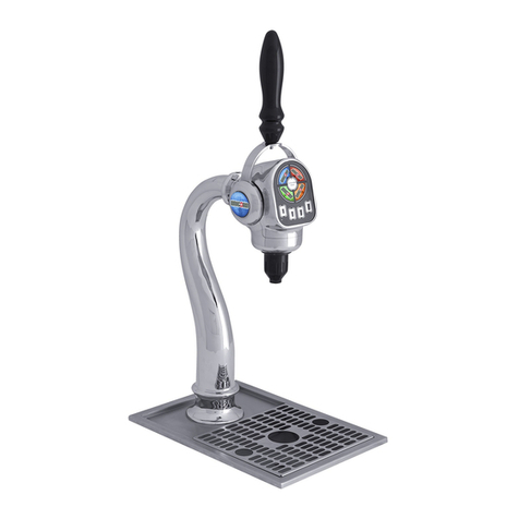
Ecolab SCLS IV User manual

TABLE OFCONTENTS
1.1
SystemIntroduction.......................................................1-1
1.2
Preface .......................................................................................................
1-1
1.3
SystemFeatures ........................................................................................1-1
2.1
Requirements/Specifications.....................................2-1
2.2
Utility Requirements....................................................................... 2-1
2.2.1
Electrical Supply Requirements… ....................................................2-1
2.2.2
WaterSupply Requirements .................................................. 2-1
2.2.3
Electrical
..........................................................................................
2-1
2.3
Specifications .............................................................................2-2
2.3.1
Dimensions
...................................................................................................
2-2
3.1
System Installation.....................................................3-1
3.2
Installation Procedure..................................................................... 3-1
3.1.1 Mounting the SCLS IV to the SCLS .............................................3-1
3.3
Wiring (wiring diagram belowFigure 3-2).......................................... 3-2
3.4
Plumbing........................................................................................ 3-3
4.0 System Programming ................................................4-1
5.0 Startup and Operation ...............................................5-1
6.1
Troubleshooting.........................................................6-1
6.2
Product not dispensing ........................................................................6-1
7.0 Replacement Parts....................................................7-1

1.1
System Introduction
1.2
Preface
This manual presents the basic installation, operation, programming and servicing instructions for the SCLS
IV/AQUANOMIC EU IV DISPENSING MODULE. This manual applies, in its entirety, to current equipment.
Guidelines are suggested in reference to the preferred method of installation, however, the surrounding
physicalenvironmentdictatetheactualinstallationoftheSCLSIV/AQUANOMIC EUIV DISPENSING MODULE.
This system will convert the standard three product dispenser to a four product dispenser.
WARNING: These installation, operation and servicing instructions are for use by qualified personnel
only. The installation must be made in accordance with local plumbing and electrical codes.
1.3
SystemFeatures
The SCLS IV/AQUANOMIC EU IV DISPENSING MODULE unit offers the following features:
•Addition of a fourth product will give improved application flexibility.
•
Accurate dispensing of the fourth solid product through the SCLS/
AQUANOMICEUdispenser.
•Thefourthsolidproducthastheemptycapsulealarm.
•Thefourthproduct willbedischarged through thecurrentpump andconductivitycell.
•Twotypesofproductcapsuleswillbeprovidedtopreventemployeesfromswapping
pocketswhen twounitsand twotypesofproductareat the samelocation.
SCLS IV/AQUANOMIC EU IV Dispensing Module Installation & Operation Manual
1-1

Pre & Post
Flush
Nozzle
SCLSIV/AQUANOMIC
EUIV
Dispensing Module
Product Nozzle
Vacuum
Breaker
Detergent
Nozzle
Pre & Post
Flush Nozzle
Bleach
Nozzle
Sour/
Softene
r Nozzle
Sump
Detergent
Solenoid
Valve
Sump
Bleach
Solenoid
Valve
Pressure
Gauge
N.O.
N.C
Softene
r
Control
Valve
Main
Solenoid
Valve
Pump Inlet Hose
Regulator
Water Strainer
Inlet Assembly
Pump
Discharge
Manifold
Thermistor
Conductivity Cell
Electrodes
Laundry Machine #2
Solenoid
Laundry Machine #1
Solenoid
Hydraulic Diagram
Check Valves
Figure 1-1

1-2 SCLS IV/AQUANOMICEU IV Dispensing Module Installation & Operation Manual

2.1
Requirements/Specifications
2.2
Utility Requirements
2.2.1
ElectricalSupplyRequirements
•
A constant 120 VAC/60Hz. power source is required.
•
The pump Cabinet is shipped with a 9’ power cord.
•Fordistancegreaterthan9’, the PumpCabinetmustbehardwiredwithconduit.
•
The double pole single throw ON/OFF switch is also a circuit breaker rated at 3.0 amps.
•
Totalamperage draw during normal operation is approximately 2.5 amps.
2.2.2
WaterSupplyRequirements
•A3/8” MNHThotwatersupplylineisrequired.TheNSFhoseisshippedintheInstallationKit.
•Watertemperatureshould not fallbelow95°F (35°C).
•
Water flow rate is 0.8 GPM.
2.2.3
Electrical
The SCLS IV/AQUANOMICEU IV does not require any additional electrical or water service relative to the main
dispenser. The SCLS IV/AQUANOMICEU IV runs on 24 volt electrical service originating from the main
dispenser cabinet. The SCLS IV/AQUANOMICEU IV uses water from the main dispenser and therefore does
not require additional water hook up.
SCLS IV/AQUANOMIC EU IV Dispensing Module Installation & Operation Manual 2-1

2.2
Specifications
The following section discusses the cabinet space and service access requirements:
2.2.1
Dimensions
The dispenser module assembly has the following dimensions.
• Height....................20 1/4” (including standpipe 22”)
• Width ....................10 1/4”
• Depth .....................11”
•
Weight...................15lbs.(withproductupto21lbs.)
•Productclearanceneedstobe8” abovethecabinettoreplaceproductcapsules.
2-2 SCLS IV/AQUANOMIC EU IV Dispensing Module Installation & Operation Manual
W
Figure 2-1

3.1
SystemInstallation
3.2
Installation Procedure
1.
Remove the protective label from the SCLS/AQUANOMIC EU cabinet’s left hand side. The label needs to be
removed in order to run the electrical and hydraulic service between the dispensers.
2.
If the SCLS/AQUANOMICEU has already been installed remove the cabinet from the wall per the
following instructions.
a.
Unplug the cabinet.
b.
Disconnect the communications cables.
c.
Turn off the watersupply.
d.
Disconnecttheproductdeliverytubing.
e.
Removetheoverflowhose.
f.
Remove the solid products.
g.
Remove Cabinet from the wall.
3.1.1 Mounting the dispenser.
1.
Install the mounting brackets according to Figure 3-1 below.
SCLS IV/AQUANOMICEU IVModule Bracket SCLS/AQUANOMIC EU Bracket
2.
Hang cabinets on the brackets with the SCLS IV/AQUANOMICEU IV to the left of the
SCLS/AQUANOMIC EU cabinet.
Figure 3-1
NOTE: Remove the protective label from the left side of the SCLS/Aquanomic EU cabinet prior to
hanging the cabinets.

SCLS IV/AQUANOMIC EU IV Dispensing Module Installation & Operation Manual 3-1

3.2
Wiring (wiring diagram below Figure 3-2)
1.
Unwindthewhite/orange–orangeandwhite/red–redwirepairsintheSCLS/AQUANOMICEUcabinetand
feed through the tophole inthe left side ofthecabinet.
2.
Crimp a female quick disconnect to each of the four wires.
3.
Connect the orange wire to the male quick disconnect of the reed switch assembly (white wires).
4.
Connect the white/orange wire to the open 1/4” tab of the 4th product valve.
5.
Connect the red andthewhite/redwires to the open tabson the flushvalve.
SCLS IV/AQUANOMICEUIV cabinet SCLS/AQUANOMIC EUcabinet
Figure 3-2
3-2 SCLS IV/AQUANOMIC EU IV Dispensing Module Installation & Operation Manual
SAFETY
WHT WHT
FLUSH
VALVE
4TH PRODUCT
VA LV E
12–PIN CONNECTOR TO J7, ON CPUBOARD
ORG WHT/ORG
RED
RED
ORG

3.3
Plumbing
1.
Cutthe 1/4” white tubing which
supplies water to
thedetergentvalveapproximately3” beforethe
detergentvalveasshowninFigure3-3.
2.
Insert a tube insert into each end of the 1/4” white tubing just cut and insert the tube ends into the T
connector.
3.
Feed the 1/4” white tubing from the SCLS IV/AQUANOMIC EU IV cabinet through the top hole on the left
side of theSCLSIV/AQUANOMICEUIVcabinet.
4.
Connect this 1/4” whitetubingintothe Tconnector.
VACUUM
BREAKER
DETERGENT
VALVE
4TH PRODUCT
T
CONNECTOR
PRODUCT
SUMP SUMP
VALVE SOUR/SOFTENER
VA LV E
FLUSH
VALVE BLEACH
VALVE
TUBE
INSERTS
CUT 1/4”
WHITE
TUBING
SCLS IV/
AQUANOMIC EU IV
CABINET
SCLS/
AQUANOMIC EU
CABINET
Figure 3-3

SCLS IV/AQUANOMIC EU IV Dispensing Module Installation & Operation Manual 3-3

3.3 Plumbing
(Continued)
5.
Remove the plug from the sump drain hose (located above the pump inlet) in the SCLS/
AQUANOMICEUcabinet.
6.
Feed the 4th product drain hose through the bottom hole on the left side of the SCLS/AQUANOMIC EU
cabinet.
7.
Attach the 4th product drain hose to the SCLS/AQUANOMIC EU drain hose using the connector tube and
two hose clamps as shown in Figure 3-4 below. Be sure drain tube is not kinked. Shorten length if
necessary.
HOSE CLAMP
SCLS IV (9259-
1097)/ AQUANOMIC
EU IV CABINET
(9259–1000)
SCLS CABINET/
AQUANOMIC EU
Figure 3-4
4TH PRODUCT
SUMP
SUMPOUTLET
HOSE
CLAMPS
4TH PRODUCT
DRAIN TUBE
DRAIN TUBE
TUBE INSERT
PUMP INLET

3-4 SCLS IV/AQUANOMIC EU IV Dispensing Module Installation & Operation Manual

4.0 SystemProgramming
AllSCLSIV/AQUANOMIC EUIVprogrammingiscarriedoutattheSCLS/AQUANOMIC EU dispenser
according to the following steps.
1.
Enter programming mode of the SCLS/AQUANOMICEUdispenser by pressing the [Program]key,your
password (default is 12345) and then the [Enter] key.
2.
Press the down arrow key until the cursor is located in front of the System Menu and then press the
[Enter] key.
3.
Press the down arrow key until the cursor is located in front of the “Fourth Product” selection, then press
[Enter].
4.
The “Fourth Product Installed” screen should be displayed. Press the [Choice] key until the Yesresponse is
indicated and then press the [Enter] key to save the change.
5.
Pressthe[Exit] key,thedown arrowkeyandthen the [Enter]key inordertoaccess the “Formula Menu”.
6.
Edit the programmed formulas by selecting washer number, formula number and the edit grams/delay
choices. The gram amounts for the fourth product will be visible after the finish product grams. Forfurther
informationpleaseseetheSCLS/AQUANOMIC EU I/OManual(Section6.6.2.4).
SCLS IV/AQUANOMIC EU IV Dispensing Module Installation & Operation Manual 4-1

5.0 Startup andOperation
1.
If both the SCLS/AQUANOMIC EU and the SCLS IV/AQUANOMICEUIV are being installed at the same
time, complete the startup and operation of the SCLS/AQUANOMIC EU (Section 5.0, SCLS/AQUANOMIC
EUI/O Manual) prior toproceeding tostep2.
2.
At the SCLS/AQUANOMIC EU pump cabinet enter the program mode by pressing the [Program] key followed
by the password (default is 12345) and then the [Enter] key.
3.
Pressthe down arrowuntil the cursorindicatesthe “Diagnostic Menu” and then press the [Enter]key.
4.
Pressthe down arrowkey until the cursor gets to Outputs then press [Enter].
5.
Place a product capsule on the Fourth Product Dispenser.
6.
Inthe Outputs menu press[On/Off]keyto turn themainflushdisplaytoon. PresstheDown arrowonce
andthenpress[On/Off]keytoturnwasher1displaytoon.PresstheDownArrowsixtimes andthenpress
[On/Off] key to turn the Product 4 display to
ON
. Press the [Enter] key. Verify that product is flowing over
totheFourthproductcabinetandbeingpumpedtoWasher1.
7.
PresstheDownArrowseventimesandthenpress[On/Off]keytoturn theProduct4 display to
OFF
.Press
the [Enter] key.
8.
PresstheDownArroweighttimes andthenpress[On/Off]keytoturntheP4Flush display to
ON
.Press
the [Enter] key. Verify that water is flowing over to the Fourth product cabinet and being pumped to
Washer 1.
9.
Press the [Exit] key twice to turn off alloutputs.
SCLS IV/AQUANOMIC EU IV Dispensing Module Installation & Operation Manual 5-1

6.0Troubleshooting
Symptom
Possible Cause
Action
6.1 Product not dispensing
1.
Product Capsule switch
a. Use ohm meter and check
continuity through the
switch. Switch is normally
open.
2. Bad product valve
a.
Solenoid diaphragm failed
b.
Coil failed
c.
With cabinet dispensing
product, check for 24 VAC
onthecoilleads.Removethe
leads from the coil totest.
d.
If 24VACis present, replace
the coil.
e.
If 24VACis not present,
replacetheCPUmodule.
SCLS IV/AQUANOMIC EU IV Dispensing Module Installation & Operation Manual 6-1

7.1
ReplacementParts
SCLS IV/AQUANOMIC EU IV DISPENSING MODULE
1 2 11 SUMP & CABINET
REF.
NO.PART NO.DESCRIPTION
9
12
10
13, 14
•
PART NOT SHOWN
7
8
SPRAYTUBE DETAIL FLUSH TUBE DETAIL
SCLS IV/AQUANOMIC EU IV Dispensing Module Installation & Operation Manual 7-1
1
9252-0634
COVER ASSEMBLY
2
8305-1136
PROXIMITY SWITCH
3
9258-2592
FLUSH SPRAY TUBE
4
9259-2640
PRODUCT SPRAY TUBE
5
8531-2718
FLUSH NOZZLE 180° SPRAY SST
6
8531-2502
PRODUCT NOZZLE 67° KYNAR
7
8720-6165
O-RING EPDM
8
9258-2600
SPRAY TUBE NUT
9
9204-2050
COIL, 24 VAC
10
8563-5795
ELBOW, 3/8T X 1/4MNPT
11
9258-4184
DETENT SWITCH BRACKET
12
8614-9127
BUSHING REDUCER
13
8554-5051
TEE, 3/8T X 3/8T X 1/4MNPT
14
9321-2135
TEE, 3/8T X 3/8T X 3/8T
•
9258-1005
DRAIN TUBE ASSEMBLY
•
9258-4291
LOCKOUT & SUMP LUGS
This manual suits for next models
1
Table of contents
Other Ecolab Dispenser manuals


