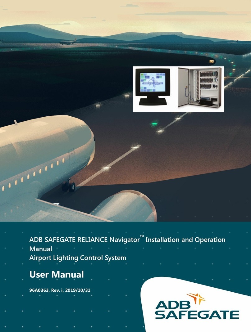
ADB Safegate RELIANCE User manual

RELIANCE Touchscreen Airfield Lighting Control and Monitoring
Systems (ALCMS)
User Manual
96A0270, Rev. K, 2020/06/26


A.0 Disclaimer / Standard Warranty
CE certification
The equipment listed as CE certified means that the product complies with the essential requirements concerning safety and
hygiene. The European directives that have been taken into consideration in the design are available on written request to
ADB SAFEGATE.
ETL certification
The equipment listed as ETL certified means that the product complies with the essential requirements concerning safety and
FAA Airfield regulations. The FAA directives that have been taken into consideration in the design are available on written
request to ADB SAFEGATE.
All Products Guarantee
ADB SAFEGATE will correct by repair or replacement per the applicable guarantee above, at its option, equipment or parts
which fail because of mechanical, electrical or physical defects, provided that the goods have been properly handled and
stored prior to installation, properly installed and properly operated after installation, and provided further that Buyer gives
ADB SAFEGATE written notice of such defects after delivery of the goods to Buyer. Refer to the Safety section for more
information on Material Handling Precautions and Storage precautions that must be followed.
ADB SAFEGATE reserves the right to examine goods upon which a claim is made. Said goods must be presented in the same
condition as when the defect therein was discovered. ADB SAFEGATE furthers reserves the right to require the return of such
goods to establish any claim.
ADB SAFEGATE's obligation under this guarantee is limited to making repair or replacement within a reasonable time after
receipt of such written notice and does not include any other costs such as the cost of removal of defective part, installation
of repaired product, labor or consequential damages of any kind, the exclusive remedy being to require such new parts to be
furnished.
ADB SAFEGATE's liability under no circumstances will exceed the contract price of goods claimed to be defective. Any returns
under this guarantee are to be on a transportation charges prepaid basis. For products not manufactured by, but sold by ADB
SAFEGATE, warranty is limited to that extended by the original manufacturer. This is ADB SAFEGATE's sole guarantee and
warranty with respect to the goods; there are no express warranties or warranties of fitness for any particular purpose or any
implied warranties of fitness for any particular purpose or any implied warranties other than those made expressly herein. All
such warranties being expressly disclaimed.
Standard Products Guarantee
Products of ADB SAFEGATE manufacture are guaranteed against mechanical, electrical, and physical defects (excluding lamps)
which may occur during proper and normal use for a period of two years from the date of ex-works delivery, and are
guaranteed to be merchantable and fit for the ordinary purposes for which such products are made.
Note
See your sales order contract for a complete warranty description.
FAA Certified product installed in the United States and purchased or funded with monies through the
Airport Improvement Program (AIP) installations guarantee
ADB SAFEGATE L858 Airfield Guidance Signs are warranted against mechanical and physical defects in design or manufacture
for a period of 2 years from date of installation, per FAA AC 150/5345-44 (applicable edition).
ADB SAFEGATE L858(L) Airfield Guidance Signs are warranted against electrical defects in design or manufacture of the LED or
LED specific circuitry for a period of 4 years from date of installation, per FAA EB67 (applicable edition).
ADB SAFEGATE LED light fixtures (with the exception of obstruction lighting) are warranted against electrical defects in design
or manufacture of the LED or LED specific circuitry for a period of 4 years from date of installation, per FAA EB67 (applicable
edition). .
96A0270, Rev. K, 2020/06/26 iii
Copyright © ADB Safegate, All Rights Reserved

Note
See your sales order contract for a complete warranty description.
Liability
WARNING
Use of the equipment in ways other than described in the catalog leaflet and the manual may result in personal injury,
death, or property and equipment damage. Use this equipment only as described in the manual.
ADB SAFEGATE cannot be held responsible for injuries or damages resulting from non-standard, unintended uses of its
equipment. The equipment is designed and intended only for the purpose described in the manual. Uses not described in the
manual are considered unintended uses and may result in serious personal injury, death or property damage.
Unintended uses, includes the following actions:
•Making changes to equipment that have not been recommended or described in this manual or using parts that are not
genuine ADB SAFEGATE replacement parts or accessories.
•Failing to make sure that auxiliary equipment complies with approval agency requirements, local codes, and all applicable
safety standards if not in contradiction with the general rules.
•Using materials or auxiliary equipment that are inappropriate or incompatible with your ADB SAFEGATE equipment.
•Allowing unskilled personnel to perform any task on or with the equipment.
© ADB SAFEGATE BV
This manual or parts thereof may not be reproduced, stored in a retrieval system, or transmitted, in any form or by any means,
electronic, mechanical, photocopying, recording, nor otherwise, without ADB SAFEGATE BV's prior written consent.
This manual could contain technical inaccuracies or typographical errors. ADB SAFEGATE BV reserves the right to revise this
manual from time to time in the contents thereof without obligation of ADB SAFEGATE BV to notify any person of such
revision or change. Details and values given in this manual are average values and have been compiled with care. They are not
binding, however, and ADB SAFEGATE BV disclaims any liability for damages or detriments suffered as a result of reliance on
the information given herein or the use of products, processes or equipment to which this manual refers. No warranty is made
that the use of the information or of the products, processes or equipment to which this manual refers will not infringe any
third party's patents or rights. The information given does not release the buyer from making their own experiments and
tests.
RELIANCE Touchscreen Airfield Lighting Control and Monitoring Systems (ALCMS)
iv
Copyright © ADB Safegate, All Rights Reserved

TABLE OF CONTENTS
1.0 RELIANCE ALCMS ................................................................................................................................................................... 1
1.1 How to work with the manual .............................................................................................................................................................................. 1
1.2 Definition of Terms ................................................................................................................................................................................................... 1
1.3 Airport Lighting Control & Monitoring System ............................................................................................................................................ 2
1.3.1 Environmental Protection .......................................................................................................................................................................... 7
1.4 Touchscreen Operation ........................................................................................................................................................................................... 7
1.4.1 Background ..................................................................................................................................................................................................... 7
1.4.2 Touchscreen Buttons ................................................................................................................................................................................... 8
1.4.3 User Input ........................................................................................................................................................................................................ 8
1.4.4 Touchscreen Pages ....................................................................................................................................................................................... 8
1.4.5 Circuit Selection Buttons ........................................................................................................................................................................... 9
1.4.6 1-Step Brightness Selection Buttons .................................................................................................................................................... 9
1.4.7 3-Step Brightness Selection Buttons .................................................................................................................................................. 10
1.4.8 5-Step Brightness Selection Buttons .................................................................................................................................................. 10
1.4.9 Confirmation Buttons ............................................................................................................................................................................... 10
1.4.10 CCR Ramping ............................................................................................................................................................................................ 10
1.4.11 Airport Operation Status Field ........................................................................................................................................................... 11
1.4.12 Sunrise/Sunset Notification (Optional Feature) .......................................................................................................................... 11
1.4.13 Touchscreen Mode Field and Time Field ........................................................................................................................................ 11
1.4.14 Alarm Display and Alarm Silence Buttons ..................................................................................................................................... 11
1.5 Touchscreen Pages ................................................................................................................................................................................................. 12
1.5.1 Overview ....................................................................................................................................................................................................... 12
1.5.2 Preset Page ................................................................................................................................................................................................... 12
1.5.3 Lighting Control Pages ............................................................................................................................................................................ 14
1.5.4 Utility Page ................................................................................................................................................................................................... 16
1.6 Touchscreen Alarms ............................................................................................................................................................................................... 21
1.6.1 Overview ....................................................................................................................................................................................................... 21
1.6.2 Power Page (OPTIONAL PAGE) ............................................................................................................................................................. 22
1.6.3 Stopbar Page (OPTIONAL PAGE) .......................................................................................................................................................... 23
A.0 SUPPORT .............................................................................................................................................................................. 25
A.1 ADB SAFEGATE Website ...................................................................................................................................................................................... 25
A.2 Recycling .................................................................................................................................................................................................................... 26
A.2.1 Local Authority Recycling ....................................................................................................................................................................... 26
A.2.2 ADB SAFEGATE Recycling ....................................................................................................................................................................... 26
96A0270, Rev. K, 2020/06/26 v
Copyright © ADB Safegate, All Rights Reserved

RELIANCE Touchscreen Airfield Lighting Control and Monitoring Systems (ALCMS)
TABLE OF CONTENTS
vi
Copyright © ADB Safegate, All Rights Reserved

1.0 RELIANCE ALCMS
Operation Manual
The manual shows the information necessary to:
•Install
•Carry out maintenance
•Carry out troubleshooting on RELIANCE ALCMS.
1.1 How to work with the manual
1. Familiarize yourself with the structure and content.
2. Carry out the actions completely and in the given sequence.
1.2 Definition of Terms
Term or abbreviation Description
RELIANCE ALCMS Airfield Lighting Control and Monitoring System
ATC Air Traffic Control
ATCT Air Traffic Control Tower
C/L Center Line
CCR Constant Current Regulator
FAA Federal Aviation Administration
ICAO International Civil Aviation Organization
LCD Liquid Crystal Display
SMGCS Surface Movement Guidance and Control System
96A0270, Rev. K, 2020/06/26 1
Copyright © ADB Safegate, All Rights Reserved

1.3 Airport Lighting Control & Monitoring System
Compliance with Standards
FAA: L-890 AC 150/5345-56 (Current Edition). ETL Certified.
ICAO: Annex 14, Vol. 1, para. 5.3 and 8.3 and Aerodrome Design Manual part 5, para. 3.4 and 3.7.
Military: UFC 3-353-01 par. 15-3.
System Overview
The RELIANCE® Elite Airport Lighting Control and Monitoring System (ALCMS) provides state-of-the-art programmable
intelligence for control and monitoring of airfield lighting circuits to meet FAA Airport Lighting Control and Monitoring
System L-890XY. The ALCMS can automatically control and monitor stop bars or runway guard lights as part of a Surface
Movement Guidance and Control System (SMGCS). In addition, the system can control and monitor Land and Hold Short
systems (LAHSO) and can be customized to interface with Constant Current Regulators (CCRs), generators, approach lighting,
or other devices requiring remote control and/or monitoring. The system can also be used in remote deicing stations and
remote air terminal applications. RELIANCE Elite is unmatched in performance, long-term reliability, and flexibility with many
standard features and a wide range of innovative, cost-effective options.
Features
•Real-time status of the airfield lighting system
•Distributed control and monitoring PC-based design
•Realistic airfield graphic displays provide detailed information to air traffic controllers and maintenance personnel
•Touchscreen Creations™ software, developed specifically for airfield lighting applications, provides a powerful and flexible
means for airport personnel to make modifications to the lighting system after initial installation
•Time-saving diagnostics and monitoring from remote locations
•Redundant network configurations are available using any combination of Ethernet, fiber optics, hard-wire, and wireless
•Easily integrated into existing airport Ethernet networks
Open-architecture design offers easy integration of the latest technology. (Examples: LAHSO, in-pavement and elevated
Runway Guard Light systems, Stop Bars, etc.)
Applications
RELIANCE Elite ALCMS offers a modular design that gives airports the flexibility to easily expand their system as their
requirements change and as new FAA regulations require additional capabilities. The open architecture of the ALCMS allows
the system to be integrated with any of the latest advanced technologies in airport systems.
Such systems include:
•RELIANCE® Intelligent Lighting systems (power-line carrier technology) - Offer individual lamp control/monitoring, sign
monitoring, stop bar, in-pavement or elevated runway guard light control/monitoring, and taxiway routing.
•Surface Movement Surveillance Systems - Provide an integrated workstation that allows lighting control, aircraft tracking,
aircraft tagging, and ground movement conflict detection (i.e. runway incursion detection).
•Deicing Stations - Advanced routing control and lamps-out monitoring of aircraft deicing station lights.
•Approach Systems - Advanced control and monitoring of the approach system steady burning lights and the strobe
system.
•Remote Air Terminals - Using ADB SAFEGATE's surface guidance system, remote air terminal personnel can control and
monitor taxi lanes/apron areas between the main airport surface movement area and a remotely-owned/operated air
terminal.
•Land and Hold Short Systems - Indicate the location of hold-short points on runways approved for land and hold short
operations.
RELIANCE Touchscreen Airfield Lighting Control and Monitoring Systems (ALCMS)
RELIANCE ALCMS
2
Copyright © ADB Safegate, All Rights Reserved

Advanced Control Equipment (ACE™)
RELIANCE Elite design uses the Advanced Control Equipment (ACE) unit to provide distributed control rather than a
centralized system of discrete I/O modules. This dramatically simplifies computer system wiring to the airport's CCRs. With the
ACE system, all control and monitoring signals are transferred through a pair of redundant high-speed data buses, eliminating
the hundreds of discrete wire connections found in traditional installations. The use of quick disconnects and standard 18-20
gauge shielded, twisted-pair cabling for the data buses greatly simplifies installation and maintenance. An unlimited number
of CCRs can be accommodated by simply adding additional data buses as required. Data bus redundancy ensures continuous
operation in the event one of the buses fails.
The ACE module consists of an integrated control unit that is interfaced to each CCR either internally or within a small
external enclosure. Optional packages can be added depending on system requirements. The ACE module features very quick
control response, unparalleled monitoring performance (current/voltage is sampled 50.000 times/sec), and built-in
programmable fail-safe modes. Configuration and calibration of the ACE system is performed directly through the ALCMS
user interface, eliminating the need for dedicated programming devices or laptop computers. For stand-alone ACE
applications, configuration is easily performed using buttons on the front of the ACE display. See ADB SAFEGATE data sheet
3097 for additional information on this product.
Control
•Programmable preset lighting controls automate common procedures
•Touchscreen - Single or multiple touchscreen control stations can be integrated within the ALCMS with built-in transfer
procedures
•Provisions for air-to-ground radio control of the airport lighting
•Soft-start control feature provides programmable delays between intensity step switching
•Programmable smart fail-safe provides mechanically latching or preset fail-safe design to meet the airport requirements
•Maintenance lock-out feature allows circuit maintenance, graphical maintenance indication and circuit control protection
Monitoring
•Real-time monitoring functions
•Capable of monitoring constant current regulators, circuit selectors and any non-regulated circuit
•Custom monitoring options provide the flexibility to configure for full L-827 monitoring or simple current sensing relay
monitoring
•ADB SAFEGATE's optional AirSide® Remote Management System (A-RMS) provides secure remote access to the ALCMS
via the airport's secure network. Access is provided via a high-speed VPN connection device and software that allows ADB
SAFEGATE service engineers and/or airport personnel to monitor and service an airport's ALCMS from a remote location.
For more information about ADB SAFEGATE’s A-RMS, see data sheet 3079
Alarm Reporting
•Extensive searching and reporting capabilities
•Alarming capabilities to meet the requirements of each airport
•Alarming tolerances are configurable to adjust sensitivity
•Alarm and event filtering provides the flexibility to control messages to the airport traffic control tower and maintenance
96A0270, Rev. K, 2020/06/26 3
Copyright © ADB Safegate, All Rights Reserved

•Search filters can sort based on date, range of dates, circuit, regulator, reported location and type of alarm
•Report hard-copy printing and exporting to electronic file
Ordering Code
Monitoring Option
A = Control Only
B = Basic Monitoring
C = Advanced Monitoring
D = SMGCS Ready
Fail-safe Option
A = Preset
B = Last State
Notes
1. Call ADB Sales Department for complete description of configuration
options.
ALCMS - X X
Touchscreen
Multiple Touchscreen Control Stations (TCS) can be integrated within an ALCMS. Each TCS may share control of an airfield or
have a specific area of control. Each TCS operates independently of one another and provides complete redundancy for
airfield lighting control and monitoring.
Features
•High-definition airfield graphic representation
•High-contrast, anti-glare monitors
•LCD flat screen displays
•Intuitive user interface provides ‘pop-up’ buttons that lead the air traffic controllers through lighting control tasks
•Highly flexible preset or selective airfield lighting control
•Programmable event and alarm filters reduce information overload for air traffic controllers
•Easily integrated with SMGCS operation requirements (i.e. stop bar control/monitoring and taxiway routing)
Maintenance Center
The Maintenance Center provides the airport with convenient ALCMS status monitoring from any remote location, on or off
the airfield.
RELIANCE Touchscreen Airfield Lighting Control and Monitoring Systems (ALCMS)
RELIANCE ALCMS
4
Copyright © ADB Safegate, All Rights Reserved

The maintenance computer(s) provides real-time and historical information regarding the status of the airfield lighting as well
as any other device that is being controlled and/or monitored by the ALCMS.
Graphics
The detailed graphical displays provide quick status of the airfield lighting systems. High-resolution graphics are fully scalable
and allow for detailed zooms of any portion of the airfield.
Features
The Maintenance Center provides valuable maintenance tools that allow quick diagnosis and maintenance of the system.
Some of the tools available are as follows:
•Remote Lighting Control - A password-protected window allows airport personnel control of the airfield lighting from
locations other than the tower, such as the maintenance center, computer operations center, and other lighting vaults
•Report Printing - Flexible report printing capabilities allow specific data to be printed out
•On-line Documentation - Manuals and wiring diagrams are available on-line and provide easy access to important
information
•ADB SAFEGATE's optional AirSide® Remote Management System (A-RMS) provides secure remote access to the ALCMS
via the airport's secure network. Access is provided via a high-speed VPN connection device and software that allows ADB
service engineers and/or airport personnel to monitor and service an airport's ALCMS from a remote location. For more
information about ADB SAFEGATE's A-RMS, see data sheet 3079
System Options
In addition to the distributed control system, ADB SAFEGATE continues to offer traditional control systems with any or all of
the following features.
•L-821 Airfield Lighting Control Panel
•Support to existing L-827 stand-alone airport monitoring or L-829 Scanning Monitor Ready CCRs
•Industrial style I/O system
Reliance Intelligent Lighting (IL)
ADB SAFEGATE's RELIANCE Intelligent Lighting Platform II System is an integral component in Surface Movement Guidance
Control Systems (SMGCS). It is used to precisely control and monitor a single light or groups of lights on the airport runway/
taxiway series circuit.
Computerized Taxiway Stop Bar
Several stop bars may be connected to the same series circuit loop while still allowing selective switching and individual
monitoring of each stop bar.
96A0270, Rev. K, 2020/06/26 5
Copyright © ADB Safegate, All Rights Reserved

When a red stop bar is switched ON, a number of green taxiway centerline lights beyond the stop bar are switched OFF. When
the aircraft receives clearance and when the red stop bar lights are extinguished by the air traffic controller, the green
centerline lights are illuminated to indicate the aircraft is cleared to proceed. Incorporating a microwave sensor with Reliance
IL will allow automatic relighting of the stop bar and extinguishing of the green centerline lights in anticipation of the next
aircraft.
Power-line Communication Technology
Controlling and monitoring the stop bar lights, taxiway entry lights, and presence detectors are accomplished by using ADB
SAFEGATE's RELIANCE IL Remote control devices. Each device on the airfield that requires individual control and monitoring is
interfaced to one of the Remotes. All communication data is superimposed onto the airfield series circuit cabling (power-line)
and is received by the RELIANCE IL Remotes. The Remotes can also transmit a variety of monitoring data back to a RELIANCE
IL Master. See data sheet 3076 for more information on ADB SAFEGATE's RELIANCE IL System.
Please contact the ADB SAFEGATE Sales Department for more information on ADB SAFEGATE's advanced technology
products.
General Application
Notes
1 External internet connection is required via firewall of existing
wired network infrastructure or wireless 3G network. See A-RMS
data sheet (3079) for more details.
2 Typically located in either the airfield lighting electrical center,
air traffic control tower or remote monitoring station.
Air Traffic Control Tower(s) Remote Monitoring
Station(s)
ADB Safegate
Service Engineer
Wireless Roaming
Maintenance
Laptop
AirSide
Remote
Management
System1,2
®
Laser
Printer
Maintenance
Terminal
Airfield Lighting
Electrical Center B ... Z
Airfield Lighting
Electrical Center A
Control and Monitoring Network Control and Monitoring Network
Control and
Monitoring
Terminal
Control and
Monitoring
Terminal
Touchscreen
Control Station
A
Touchscreen
Control Station
B ... Z
Communication Network
ADB Safegate
RELIANCE Touchscreen Airfield Lighting Control and Monitoring Systems (ALCMS)
RELIANCE ALCMS
6
Copyright © ADB Safegate, All Rights Reserved

1.3.1 Environmental Protection
•PLC Cabinet: NEMA 12 (IP 40).
1.3.1.1 Environmental Operating Conditions
Table 1: Touchscreen/Panel PC
Operating Temperature: 0°C (+32°F) to +40°C (+104°F)
Relative Humidity: 10-95% at 40°C (non-condensing)
Table 2: PLC Cabinet
Operating Temperature: -25°C (-13°F) to +50°C (+122°F)
Relative Humidity: Up to 95%
1.3.1.2 Electrical Supply
Table 3: Touchscreen/Panel PC
Input power: Single phase, 100-240V AC, 50/60 Hz
Table 4: PLC Cabinet
Input power: Single phase, 100-264V AC, 50/60 Hz
1.4 Touchscreen Operation
1.4.1 Background
Airfield lighting control for many years was accomplished at lighting control panels (referred to as an L-821) using toggle
switches, rotary knobs, and pushbutton switches. Technology has changed and one of the changes has brought touchscreen
monitors to the cabs of Air Traffic Control Towers around the world. The Touchscreen is a very flexible tool for air traffic
controllers and has reduced the amount of time they spend controlling airfield lighting.
The Touchscreen is basically a simplified operator interface tool. There are no need for keyboards and pointing devices such
as a mouse or trackball. All of this is integrated right into the Touchscreen monitor.
1.4.1.1 Five-Wire Resistive Touchscreens
The five-wire resistive touchscreens use a glass panel with a uniform resistive coating. A thick polyester coversheet is tightly
suspended over the top of the glass, separated by small, transparent insulating dots. The coversheet has a hard, durable
coating on the outer side and a conductive coating on the inner side.
Figure 1: Resistive Touchscreen Composition
96A0270, Rev. K, 2020/06/26 7
Copyright © ADB Safegate, All Rights Reserved

When the screen is touched, the conductive coating makes electrical contact with the coating on the glass. The voltages
produced are the analog representation of the position touched. The controller digitizes these voltages and transmits them to
the computer for processing. AccuTouch five-wire technology utilizes the bottom substrate for both X and Y-axis
measurements. The flexible coversheet acts only as a voltage-measuring probe. This means the touchscreen will continue
working properly even with non-uniformity in the coversheet's conductive coating. The result is an accurate, durable and
reliable touchscreen that offers drift free operation. AccuTouch screens are sealed against contamination and moisture. This
prevents wicking of fluid between the coversheet and glass.
1.4.1.2 Installation
The touchscreen monitors are Liquid Crystal Display (LCD) and are typically located in the tower cab, but can be located
anywhere including maintenance centers or electrical airfield lighting vaults. The touchscreen can be rack-mounted, installed
in an enclosure or put on a desktop depending on the application.
1.4.1.3 Do’s and Don’ts
•Always approach the buttons directly perpendicular to the touchscreen monitor face.
•Remove finger at least one inch from the touchscreen monitor face before making another touch.
•Always keep the touchscreen free of debris such as paper, dust etc.
•Never touch the screen with wet hands.
•Avoid spilling liquids onto the screen including water, coffee etc.
•Never spray cleaner directly onto the touchscreen.
1.4.2 Touchscreen Buttons
A touchscreen button is a rectangular area on the touchscreen that is colored differently from the background color, and
responds to touch input by the user. A touch button’s color can change to indicate status. Touch buttons have two states,
released and depressed.
Figure 2 shows two touch buttons, the right button is shown in the released state (also referred to as “up”), and the left button
is shown in the depressed state (also referred to as “down”). Note the difference in the shading of the borders of the two
buttons..
Figure 2: Touch Buttons: Left depressed, right released
The released button (labeled UP) border colors are reversed from the colors of the depressed button borders. The depressed
button (labeled DOWN) shows a dark black shadow on the top and left sides, with a bright white border on the right and
bottom sides.
1.4.3 User Input
User input is accomplished by pressing any of the touchscreen touch buttons. The button will only respond when the monitor
surface is touched directly on the button. This prohibits sliding into a button, as is the case with a raised mechanical button.
1.4.4 Touchscreen Pages
Depending on the complexity of the airfield lighting control system, all necessary graphics and control buttons may not be
able to fit on a single monitor screen. In this situation, the buttons and graphics are separated onto different “ pages ”. The
term “pages” denotes the different graphics and button screens that a single touchscreen monitor can display.
RELIANCE Touchscreen Airfield Lighting Control and Monitoring Systems (ALCMS)
RELIANCE ALCMS
8
Copyright © ADB Safegate, All Rights Reserved

Figure 3 is an example of a touchscreen page that will help to illustrate the layouts of the buttons. Take a look at the figure
and find the locations of the Circuit Selection, Confirmation and Step Input buttons.
Figure 3: Button Layouts
1.4.5 Circuit Selection Buttons
There are different types of touch buttons that have different functions depending on the airfield lighting control application.
One type is the Circuit selection button . This button is directly associated with an individual airfield lighting group. Circuit
selection buttons are used to choose the desired “lighting circuit” (i.e. 08R-26L Centerline lights) to control. An example is
shown in Figure 4.
Figure 4: Circuit Selection buttons
Commanded Step: The commanded step of the circuit is displayed at the bottom of the circuit selection button after the
desired step selection is confirmed by pressing the “CONFIRM” or “OK” button.
Button and graphics color: Once the step is confirmed, the button will change color and the associated airfield graphics will
also change color indicating that the command has been recognized.
Alarm indication: If the circuit is in alarm, the button will change to red and the associated airfield graphics will also change to
red.
1.4.6 1-Step Brightness Selection Buttons
If the lighting circuit is configured to operate on a 1-step CCR or on/off circuit, the brightness step button group will not
appear after selecting the circuit. The user will either “CONFIRM” or “REJECT” the input.
96A0270, Rev. K, 2020/06/26 9
Copyright © ADB Safegate, All Rights Reserved

1.4.7 3-Step Brightness Selection Buttons
If the lighting circuit is configured to operate on a 3-step CCR, then the step button group will appear on the touchscreen as
seen in Figure 5.
Figure 5: 3 Step Control
1.4.8 5-Step Brightness Selection Buttons
If the circuit button selected controls a 5-step airfield lighting circuit, then the 5-step button group is displayed as seen in
Figure 6.
Figure 6: 5-Step Control
1.4.9 Confirmation Buttons
The confirmation buttons will appear after selecting the desired brightness step intensity. These buttons offer the operator a
final opportunity to accept or deny the touch inputs. These buttons are two (2) momentary touch buttons labeled
“CONFIRM,” and “REJECT” as seen in Figure 7.
Note
Some systems have them labeled as “OK” and “CANCEL”
Figure 7: Confirmation Buttons
To accept the inputs, press the “CONFIRM” button to send the pending command message to the ALCLMS system and make
the airfield lighting change.
To deny the inputs, press the “REJECT: button. The touch inputs will be ignored and cleared from the touchscreen.
After either the “CONFIRM” or “REJECT” momentary touch button is depressed, the input step buttons are removed from
display, and the affected circuit selector button automatically returns to the released state. The user must press both a circuit
selector button and an input step button to modify lighting intensities.
1.4.10 CCR Ramping
The user may freely choose any lighting step regardless of the current step. The computer system will automatically “ramp”
each CCR to the commanded step to eliminate stress to the CCR and lights. The operator may command a lighting circuit
directly to step five from the off state, and the computer will command the CCR(s) first to step 1, then step 2, then step 3 ...
until the commanded step 5 is reached. The time delay between each successive step change is not less than 0.5 seconds and
may be set longer for older CCR's that require more “warm-up” time.
RELIANCE Touchscreen Airfield Lighting Control and Monitoring Systems (ALCMS)
RELIANCE ALCMS
10
Copyright © ADB Safegate, All Rights Reserved

1.4.11 Airport Operation Status Field
Located on each of the touchscreen pages is the airport operation status field . This field displays the current airport operation
status. This reflects the last preset conditions that have been selected by the operator.
Figure 8: Airport Operation Status Field
The airport operation status field includes the following information:
•Operating Runway Direction: This represents the Runway(s) that are currently being used for airport operations. This is
determined by the preset selection.
•Day / Night Setting: This represents the current setting for the Day and Night selection. This is determined by the
lighting preset selection.
•Visibility Setting: This represents the current visibility setting for the airport. This is also set by the lighting preset
selection.
1.4.12 Sunrise/Sunset Notification (Optional Feature)
The notification of sunrise and sunset occurrences is a touchscreen option. If elected, the touchscreen can be pre-
programmed with the sunrise and sunset times for the installation location. When a sunrise/sunset time occurs, a full screen
pop-up window is displayed, and the audible tone is sounded to notify the user of the event. The user must press the
CONFIRM button to acknowledge the event and silence the audible tone.
No automatic lighting changes will occur during this condition, this feature is to notify the user when it is time to change
from a "DAY" setting to a "NIGHT" setting.
If your touchscreen control system does not have this feature and you wish to enable this option, please contact your local
ADB Airfield Solutions sales representative.
1.4.13 Touchscreen Mode Field and Time Field
Located on each of the touchscreen pages is the mode field and the time field . This field displays the current date and time
and also the current operating mode of the touchscreen as seen in Figure 9.
Figure 9: Mode Field and Time Field
The different operating modes are:
View Only: This indicates that the current touchscreen is operating as a view only station. This means that the user can
change between the different pages, but the touchscreen will not allow any touch inputs. The touchscreen will beep each time
the screen is touched, but will not register the touch as a valid request.
Control Mode : This indicates that the touchscreen has full control capabilities. Any and all valid touches and airfield lighting
requests will be executed.
Demo Control Mode : This indicates that the touchscreen has simulated control capabilities. The touchscreen will “act” as if it
has full control capabilities and will accept touch inputs and update graphics. However, the touchscreen is completely isolated
from the lighting control system and will not affect any airfield lighting changes. This mode is primarily used for training of
ATC and maintenance on the operation of the touchscreen.
1.4.14 Alarm Display and Alarm Silence Buttons
Located on each of the touchscreen pages is the alarm display and alarm silence button . These buttons are used in
conjunction with alarm conditions that are reported to the touchscreen. They operate as follows:
96A0270, Rev. K, 2020/06/26 11
Copyright © ADB Safegate, All Rights Reserved

Alarm Silence (Alarm Acknowledge) Button is a button that flashes red when a new alarm is present in the ALCMS. It is
pressed to silence the audible alarm and acknowledge the new alarm condition. Once an alarm is acknowledged, the button
stays solid red until the alarm is cleared and an indication will then be logged in the database and viewable in the events log.
Alarm Display Button is a button used to view the current alarms in the computer system. When pressed, this button will
open the current alarms window which provides a text listing of all currently active alarms in the ALCMS. It is useful for
informing maintenance personnel of the exact alarm in the system.
1.5 Touchscreen Pages
1.5.1 Overview
The following section describes the layout and features of the touchscreen operator interface. Included are directions to find
your way around the many pages of the touchscreen interface and understanding the graphic representations of the airfields.
Each touchscreen control station is divided into several touchscreen pages. The number and name of the pages are airport
specific.
CAUTION
For an exact representation of your airport, please refer to the touchscreen demonstration CD-ROM
provided to your trainer. This CD-ROM has a fully functional touchscreen program that mimics your
airport’s touchscreens and should be used in conjunction with this manual as part of your training.
The touchscreen pages are broken up into six (6) basic pages as follows:
1. Preset Page
2. Runway Page
3. Taxiway Page
4. Utility Page
5. Power Page (OPTIONAL FEATURE)
6. Stopbar Page (OPTIONAL FEATURE)
1.5.2 Preset Page
The preset page is the primary used page that all lighting command changes should normally take place.
1.5.2.1 What are Preset Controls
Preset controls are developed in conjunction with FAA Document Number 7110.65 and the airport. The FAA 7110.65
document defines what intensities 1-step, 3-step and 5-step circuits should be at during all levels of visibility and day or night
conditions.
Preset controls are initiated at the “Preset Page” of the touchscreen and when confirmed, execute several lighting commands
based on the preset inputs. The preset controls are developed to reduce ATC workload and decision making that involves the
airfield lighting circuits.
1.5.2.2 Selecting a Preset Condition
Preset circuits do not allow the user to specify a specific intensity selection, rather the user inputs the airport’s current
operating conditions, such as RVR (Visibility) conditions, CAT conditions, Day or Night operation and operating Runway
directions. The intensity settings for the selected conditions are “looked up” from a preset look-up table, which is a pre-
programmed table in the operating code of the touchscreen. Preset intensity look-up tables are not user alterable.
RELIANCE Touchscreen Airfield Lighting Control and Monitoring Systems (ALCMS)
RELIANCE ALCMS
12
Copyright © ADB Safegate, All Rights Reserved

After a preset condition has been confirmed, the ALCMS system then performs several lighting changes to match the
requirements for the airport.
Figure 10: Preset Control Buttons
Active Runway Selection : These buttons select which runway or runway direction is desired for airfield operations. Multiple
Runways may be selected depending on the airport.
Day / Night Setting : These buttons select between “DAY” airfield operation and “NIGHT” airfield operation. This setting will
affect the brightness intensity of the lighting circuits.
Visibility Setting : These buttons select the current airfield visibility setting. This setting will determine what lights are on or
off based on the visibility setting.
An example of the “PRESET PAGE’ is shown in Figure 11. Notice the Page buttons along the top of the screen and the
‘DIRECTION’, ‘DAY/NIGHT’ and ‘VISIBILITY’ buttons shown down the left side of the screen.
Figure 11: Preset Page
1.5.2.3 Initiating an Airfield Lighting Preset
All lighting commands should primarily be done from the “Preset Page” using the Preset control buttons. This will assure that
the correct circuits are on and that they are commanded to the correct brightness intensities.
96A0270, Rev. K, 2020/06/26 13
Copyright © ADB Safegate, All Rights Reserved

To initiate an airfield lighting preset…
1. Select a runway from the “ACTIVE RUNWAY SELECTION”
2. Select the appropriate “DAY/NIGHT SETTING”
3. Select the airport’s “VISIBILITY SETTING”
4. Select the “CONFIRM” button to send the entire preset lighting command to the ALCMS computer, or press “REJECT”
button if it is not desired to make the intensity change.
After the “CONFIRM” button is pressed, the lighting sequence is executed and the corresponding circuits will turn ON. The
step number on the circuit button(s) will change to indicate the new step level.
1.5.3 Lighting Control Pages
The circuit buttons on the lighting control pages are used to manually override any commands that were initiated by the
preset commands. Typically the lighting controls are split into a "Runway Page" and a "Taxiway Page." On these pages the user
can selectively adjust the lighting of individual runway and/or taxiway circuits.
CAUTION
If lighting changes are done using a lighting page they may not meet those required for the airport's
operating conditions. If circuits are individually turned on manually via a lighting page there is the
possibility that they may be inadvertently turned off if an ATC uses the "Preset Page" to change the
lighting. For example, if the runway lights were individually turned on the Step 5 using the "Runway
Page" and then an ATC selected "Day", "> 5 miles" visibility, the runway lights would turn OFF.
It is recommended to always use the preset controls for adjusting lighting intensities.
Figure 12: Example of a Lighting Page (Combined RWY/TWY Page)
RELIANCE Touchscreen Airfield Lighting Control and Monitoring Systems (ALCMS)
RELIANCE ALCMS
14
Copyright © ADB Safegate, All Rights Reserved
Other manuals for RELIANCE
1
Table of contents
Other ADB Safegate Control System manuals
Popular Control System manuals by other brands
Toshiba
Toshiba TOSDIC-CIE DS manual

Beijing StarFire Control Technology Co., Ltd.
Beijing StarFire Control Technology Co., Ltd. SF-2012AH-QG user manual
heatapp!
heatapp! base Short Instruction

Raven
Raven AutoBoom installation manual
Piusi
Piusi MC BOX user manual
Mitsubishi Electric
Mitsubishi Electric M800W Series Connection and set up manual
