ADB L-807 User manual

ADB Airfield Solutions
L-807 Wind Cone Hinged-pole Upgrade
Kit
Size 1 and 2 to bolted cage
Installation Manual
Document Number
ALN145, June 12, 2008,
Rev. A, 27 August 2009
ADB Airfield Solutions
Copyright © 1998 ADB Airfield Solutions. All rights reserved
P.O. Box 30829
977 Gahanna Parkway
Columbus, OH 43230
Tel. (614) 861-1304
Fax. (614) 864-2069

ALN145, Rev. A 13 October 2009
1-2 L-807 Wind Cone Hinged-pole Upgrade Kit, Installation Manual
June 12, 2008
2.0 Installing a Hinged-Pole Kit. . . . . . . . . . . . . . . . . . . . . . . . . . . . . . . . . . . . . . . . . . . . . . 2-1
2.1 Introduction . . . . . . . . . . . . . . . . . . . . . . . . . . . . . . . . . . . . . . . . . . . . . . . . . . . . . . . . . . . . . . . . . . . . . . . . 2-1
2.2 Special Tools and Equipment Required. . . . . . . . . . . . . . . . . . . . . . . . . . . . . . . . . . . . . . . . . . . . . . . . . . . 2-1
2.3 General Instructions. . . . . . . . . . . . . . . . . . . . . . . . . . . . . . . . . . . . . . . . . . . . . . . . . . . . . . . . . . . . . . . . . . 2-2
2.3.1 Disassemble the old pole . . . . . . . . . . . . . . . . . . . . . . . . . . . . . . . . . . . . . . . . . . . . . . . . . . . . . . . . . . 2-2
2.3.2 Assemble the Center-hinged Pole . . . . . . . . . . . . . . . . . . . . . . . . . . . . . . . . . . . . . . . . . . . . . . . . . . . 2-3
2.3.3 Raising the Wind Cone Assembly with New ADB Center-hinged Pole Kit. . . . . . . . . . . . . . . . . . . . . 2-4
2.3.4 Turn On Procedure. . . . . . . . . . . . . . . . . . . . . . . . . . . . . . . . . . . . . . . . . . . . . . . . . . . . . . . . . . . . . . . 2-4

Introduction
96A0345, Rev. H 13 October 2009
L-807 Wind Cone and ICAO L-807, Installation Manual 2-1
Installing a Hinged-Pole Kit
2-InstallingaHinged-Pole
Kit
2.0 Installing a Hinged-Pole
Kit 2.1 Introduction
This service bulletin provides instructions to
install a new ADB Center-hinged Pole on an
existing L-807 Windcone. Retrofit applicable to
44A6454 bolted cage assembly only.
2.2 Special Tools and Equipment
Required
Refer to Table 2.1 for the tools and equipment
required to install an ADB Center Hinged Pole
Windcone Kit.
Table 2.1. Required Equipment Not Supplied
Figure 2.1.Hinged Pole Windcone
WARNING
Read the instructions in their entirety before
starting installation.
Do not attempt to service electrical equipment if
standing water is present. Use caution when
servicing electrical equipment in a high-humidity
environment.
Use tools with insulated handles when working with
electrical equipment.
Allow only qualified personnel to perform the
following tasks. Observe and follow the safety
instructions in this document and all other related
documentation.
Read and understand the instruction label affixed to
the side of the wind cone pole on the Lowering
Instructions before lowering the pole.
Lowering the pole unassisted could result in
personal injury or damage to the pole assembly.
Do not attempt to raise the pole if the prevailing
winds are above 20 knots.
Two persons are required to remove and replace
the pole assembly to the mounting base for the L-
807 Wind Cone Assemblies.
Description
Wrenches for 3/8 inch, 1/2 inch, and 5/8 inch hex
screws and nuts
Allen hex keys for 5/64 inch, 3/16 inch and 1/4
inch
Medium size blade screwdriver
36 inch bubble level
Miniture size blade screwdriver
Anti-seize compound
L-807 Instruction Manual 96A0345
1 = For L-807 Internal and External Lit With SBOL
2 = For L-807 Unlit Without SBOL
44A6878/ X Hinged-pole Kit
The bolt pattern for the Center-hinged
Pole is the same as the Bottom-hinged
Windcone pole
General Instructions
Installing a Hinged-Pole Kit
96A0345, Rev. H 13 October 2009
2-2 L-807 Wind Cone and ICAO L-807, Installation Manual
2 - Installing a Hinged-
Pole Kit
2.3 General Instructions
Read and understand all instructions before working on the wind cone. De-energize the field circuit connected
to the wind cone before installing the new Center-hinged Pole kit. The assemblies can be powered by either a
series circuit or a voltage power.
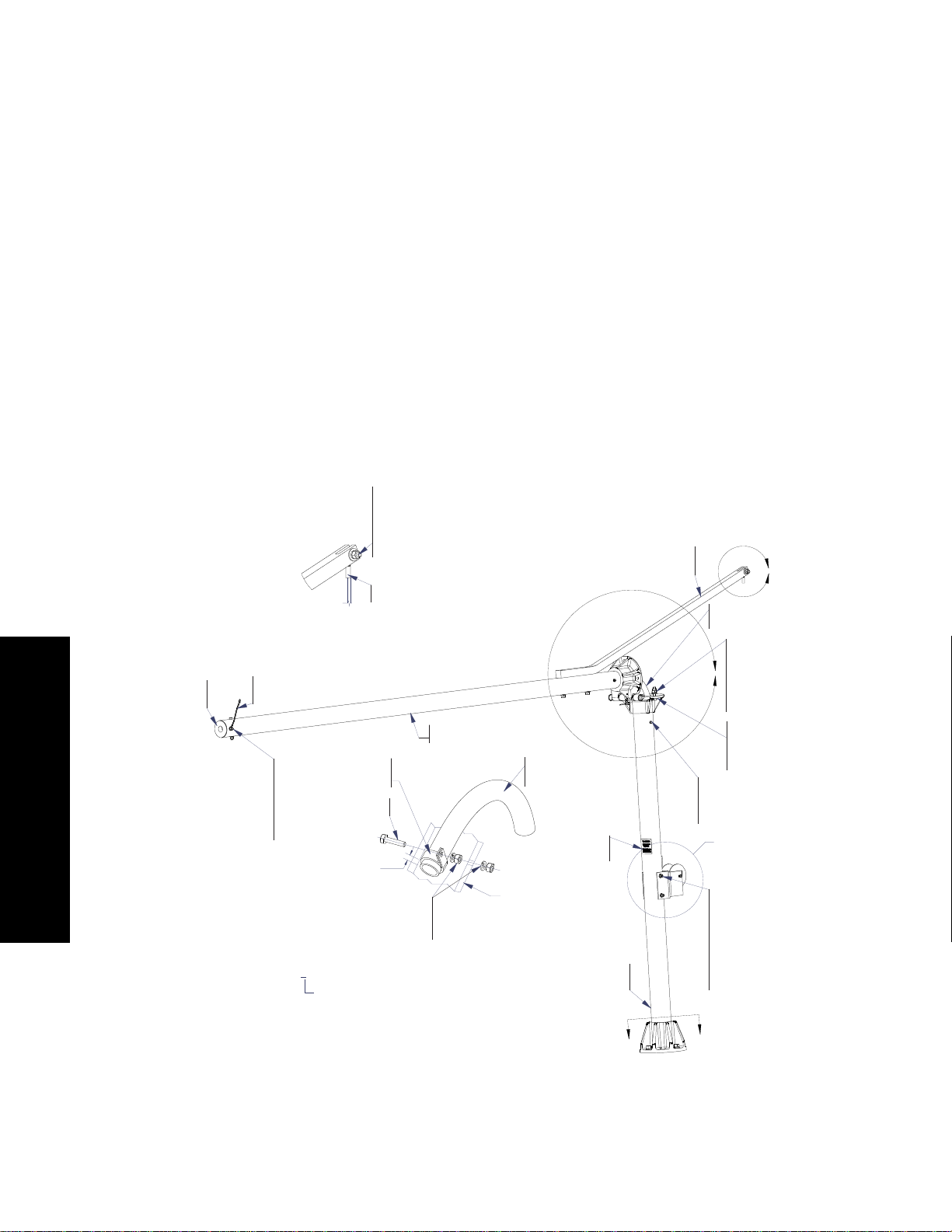
2.3.1 Disassemble the old pole
See Figure 2.2 and Figure 2.3
1. De-energize the Windcone
2. Lower the Windcone.
3. Disconnect the power leads. Loosen the cable clamps and retainers holding the power cable.
4. Pull the power cable from the Windcone pole. Disconnect the base ground strap.
5. Remove the (2) 3/8 x 4.25-inch bolts that secures the Cage assembly to the pole.
6. Remove the Windcone cage assembly carefully. Set aside for the steps to assemble the Windcone cage
assembly to the new hinged-pole.
7. Unbolt the base. Remove the old pole.
Figure 2.2.Hinged-pole diagrams 1 of 2
1 = FOR L-807 INT/EXT LIT AND/OR WITH SBOL
2 = FOR L-807 UNLIT AND WITHOUT SBOL
44A6878/ X
.30 - in
DETAIL C
E
E
A
B
3 PLACES
3 PLACES
DETAIL B
SCALE 1 : 4
DETAIL F
SCALE 1:4
TOP TUBE REF
44A6883-1
LED WINDCONE
LWR GND STRAP
60A4062
L-807 WIND CONE HINGED
POLE ADAPTER
65A0015-29
3/8-16 HX NUT
66A0015-29
3/8 FLATWASHER
66A0026-29
3/8 SPLIT LOCKWASHER
BOLT 3/8-16 X 4.25 X 1 HX HD
44A6876-2
TOP TUBE WELD ASSEMBLY
BOLT 1/4-20 X 1.25 HX
HD FULL THREAD
61A0453
1" RUBBER CUSHIONED
SS LOOP STRAP
65A0015/24
1/4-20 HX NUT, SS
66A0026/24
1/4 SPLIT LOCKWASHER
3/4 FLEXIBLE LIQ TIGHT
CONDUIT X 18 IN
77A0208
44A6876-1
BOTTOM TUBE
WELD ASSEMBLY
65A0015/33
1/2-13 HEX NUT
66A0026-33
1/2 SPLIT LOCKWASHER
BOLT 1/2-13 X 2.5 X 1.25 HEX HEAD
5/8 FLATWASHER
61A0451
25-ft WINCH CABLE 7/32" GALV 2500 lb min
42A0601
WINDCONE HINGED POLE
WARNING LABEL
60A4060
L-807 WINDCONE HINGED
POLE WINCH ATTACH BAR
77A0208
3/4 FLEXIBLE LIQ TIGHT
CONDUIT X 18 IN
65A0015/33
1/2-13 HX NUT
66A0015-33
1/2 FLATWASHER
66A0026-33
1/2 SPLIT LOCKWASHER
64A0178-32
1/2-13 X 2 HEX HD
66A0015-33
1/2 FLATWASHER
64A0173-8
1/4-20 X 1/2 HX HD
66A0026/24
1/4 SPLIT LOCKWASHER
65A0015-29
3/8-16 HX NUT
66A0015-29
3/8 FLATWASHER
66A0026-29
3/8 SPLIT LOCKWASHER
64A0176-80
3/8-16 X 5 X 1 HX HD
General Instructions
96A0345, Rev. H 13 October 2009
L-807 Wind Cone and ICAO L-807, Installation Manual 2-3
Installing a Hinged-Pole Kit
2-InstallingaHinged-Pole
Kit
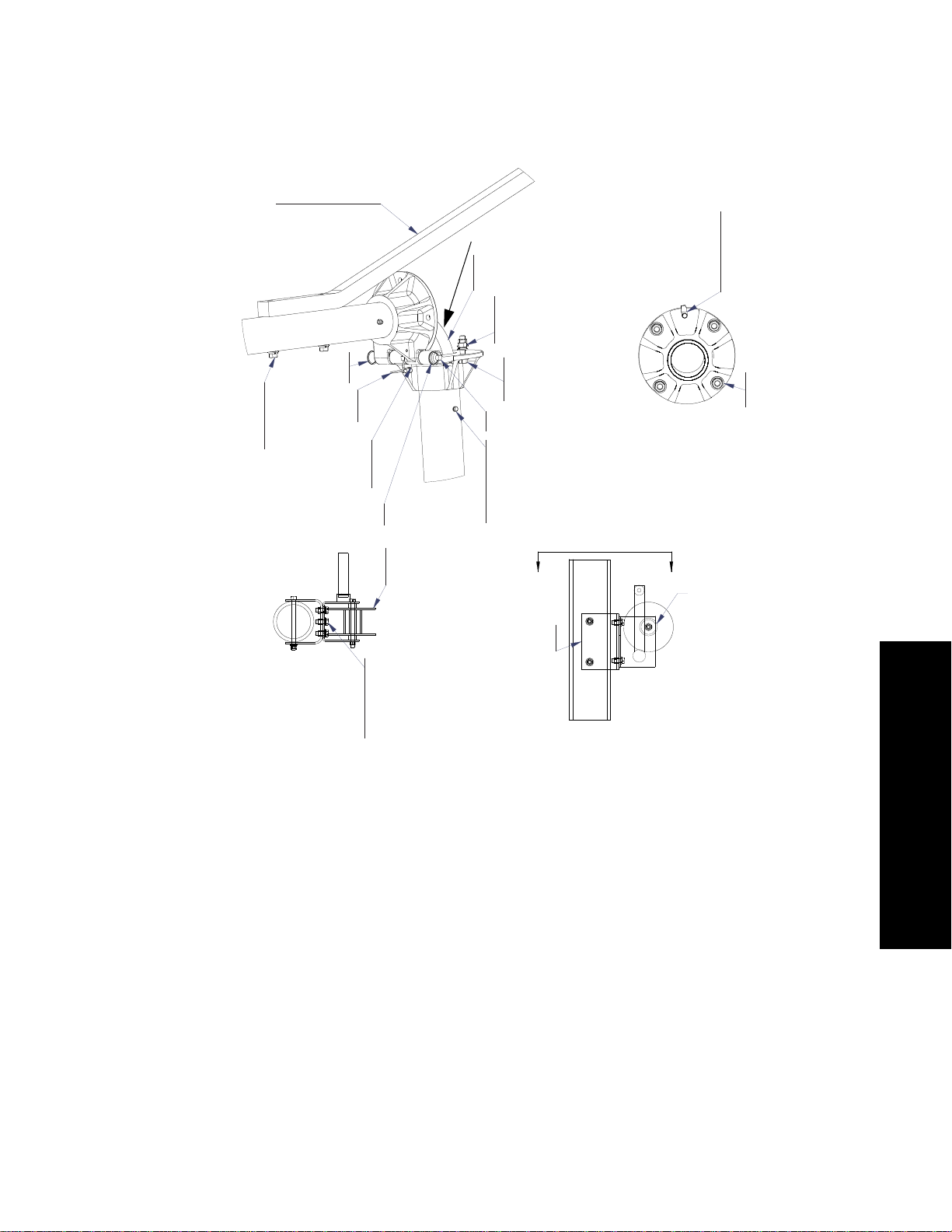
Figure 2.3.Hinged-pole diagram 2 of 2
2.3.2 Assemble the Center-hinged Pole
1. Assemble the upper and lower pole sections using the Hinge Pin and the 316 Stainless Steel Split Ring.
2. Install the 3/4-inch Flexible Conduit into the hinged opening. See Detail F.
3. Pull the Power Cable through the pole.
4. Attach the Winch Attach Bar. See Detail A. Attach the Winch Cable. See Detail B.
5. Attach the Winch to the lower pole section. See Section D-D and Detail C. Connect the Winch Cable and
remove the slack by turing the winch.
6. Connect the ground strap across the pole hinge. See Detail A.
7. Connect the pole to the Base and connect the Ground Strap. See Section E-E. Do Not Pinch the Cable.
8. Level the pole using the 8-bolts at the base. Using a level, hold in the vertical position and secure the assembly
to the base with 8 ½ inch hex nuts and flat washers. Torque the hex nuts to 40/42 foot-pounds.
9. Attach the Windcone Cage Assembly to the Pole. For the LED lighted units: Connect the Ground Strap from
the top of the pole to the upper Windcone Cage Assembly.
10. Connect the Power Leads as per the correct wiring diagram. See the L-807 Windcone and ICAO L-807 manual
96A0345.
3 PLACES
DETAIL A
SCALE 1 : 4
DETAIL C
SCALE 1:4
SEE DETAIL F
DD
SECTION D-D
SCALE 1 : 4
SECTION E-E
SCALE 1 : 4
Lubricate gears with wear &
weather resistant grease.
Plug fabrication alignment holes with noted hardware.
weld tube assembly.
2 places bottom weld tube assembly and one place top
72A0010
GROUND LUG
64A0173-12
1/4-20 X 3/4 HX HD
66A0026/24
1/4 SPLIT LOCKWASHER
5/8 FLATWASHER
5/8 SPLIT LOCKWASHER
5/8 HEX NUT
60A4060
L-807 WINDCINE HINGED
POLE WINCH ATTACH BAR
66A0015-33
1/2 FLATWASHER
66A0026-33
1/2 SPLIT LOCKWASHER
BOLT 1/2-13 X 5 X 1.25 HX HD
61A0452
316 SS SPLIT
RING 1.34 OD
44A6883-2
LED WC HINGE
GROUND STRAP
64A0173-8
1/4-20 X 1/2 HX HD
66A0038-6
1/4 INT LOCKWASHER
61A0452
316 SS SPLIT RING 1.34 OD
77A0208
3/4 FLEXIBLE LIQ TIGHT CONDUIT X 18 IN
65A0015/33
1/2-13 HX NUT
66A0015-33
1/2 FLATWASHER
64A0178-32
1/2-13 X 2 HEX HD
66A0015-33
1/2 FLATWASHER
60A4063
L-807 WINDCONE HINGE PIN
64A0173-8
1/4-20 X 1/2 HX HD
66A0026/24
1/4 SPLIT LOCKWASHER
61A0450
BRAKE WINCH
DUTTON-LAINSON
DLB1205A
64A0176/16
3/8-16 X 1 HX HD
66A0015-29
3/8 FLATWASHER
66A0026-29
3/8 SPLIT LOCKWASHER
60A4059
WINDCONE HINGED POLE
WINCH MTG BRACKET
Attach after pulling cable
Other manuals for L-807
1
Table of contents
Other ADB Industrial Equipment manuals


