ADC AD-30 User manual

AD-30 / ML-30
Installation Manual
Phase 5
ADC Part No. 113063-11
American Dryer Corporation
88 Currant Road, Fall River MA 02720-4781 USA
Telephone: +1 (269) 923-3000 / Fax: +1 (508) 678-9447
AVERTISSEMENT:
RISQUE D’INCENDIE OU D’EXPLOSION
Le non-respect des avertissements de
sécurité pourrait entraîner des blessures
graves, la mort ou des dommages
matériels.
– N’entreposer pas et n’utilisez pas
d’essence ni d’autres vapeurs ou
liquides inflammables dans le voisinage
de cet appareil ou de tout autre appareil.
– QUE FAIRE SI VOUS SENTEZ UNE
ODEUR DE GAZ
●●
●●
●Ne tentez pas d’allumer d’appareil.
●●
●●
●Ne touchez à aucun interrupteur. Ne
vous servez pas des téléphones se
trouvant dans le bâtiment où vous
vous trouvez.
●●
●●
●Évacuez la pièce, le bâtiment ou la zone.
●●
●●
●Appelez immédiatement votre
fournisseur de gaz depuis un voisin.
Suivez les instructions du fournisseur.
●●
●●
●Si vous ne pouvez rejoindre le
fournisseur de gaz, appelez le service
des incendies.
– L’installation et l’entretien doivent être
assurés par un installateur ou un service
d’entretien qualifié ou par le fournisseur
de gaz.
WARNING:
FIRE OR EXPLOSION HAZARD
Failure to follow safety warnings exactly
could result in serious injury, death or
property damage.
– Do not store or use gasoline or other
flammable vapors and liquids in the
vicinity of this or any other appliance.
– WHAT TO DO IF YOU SMELL GAS
●●
●●
●Do not try to light any appliances.
●●
●●
●Do not touch any electrical switch;
do not use any phone in your
building.
●●
●●
●Clear the room, building or area of
all occupants.
●●
●●
●Immediately call your gas supplier
from a neighbor’s phone. Follow
the gas supplier’s instructions.
●●
●●
●If you cannot reach your gas
supplier, call the fire department.
– Installation and service must be
performed by a qualified installer, service
agency or the gas supplier.
!!
!!
!!!
!!
!

We have tried to make this manual as complete as possible and hope you will find it useful. ADC reserves the right to make
changes from time to time, without notice or obligation, in prices, specifications, colors, and material, and to change or
discontinue models. The illustrations included in this manual may not depict your particular dryer exactly.
Important
For your convenience, log the following information:
DATE OFPURCHASE__________________________________________________________ MODELNO. ________________
RESELLER’SNAME ________________________________________________________________________________________
Serial Number(s) ________________________________________________________________________________________
__________________________________________________________________________________________________________
__________________________________________________________________________________________________________
Replacement parts can be obtained from your reseller or the ADCfactory. When ordering replacement parts from the factory,
you canFAX your order to ADCat+1 (508) 678-9447ortelephoneyourorder directly totheADCPartsDepartmentat+1 (269)
923-3000. Pleasespecifythedryermodelnumberandserial numberinadditiontothedescriptionandpartnumber,sothat
your order is processed accurately and promptly.
These instructions are only valid if the following country code is on the appliance… If this code is not present on the
appliance, it is necessary to refer to the technical instructions which will provide the necessary information concerning the
modification of the appliance to the condition of use for the country.
In accordance with EN ISO 3166-1, the names of countries shall be represented by the following codes:
GB United Kingdom
IE Ireland
Retain This Manual In ASafe Place For Future Reference
American Dryer Corporation products embody advanced concepts in engineering, design, and safety. If this product is
properly maintained, it will provide many years of safe, efficient, and trouble-free operation.
ONLY qualified technicians should service this equipment.
OBSERVE ALL SAFETY PRECAUTIONS displayed on the equipment or specified in the installation manual included with
the dryer.
The following “FOR YOUR SAFETY CAUTION” must be posted near the dryer in a prominent location.
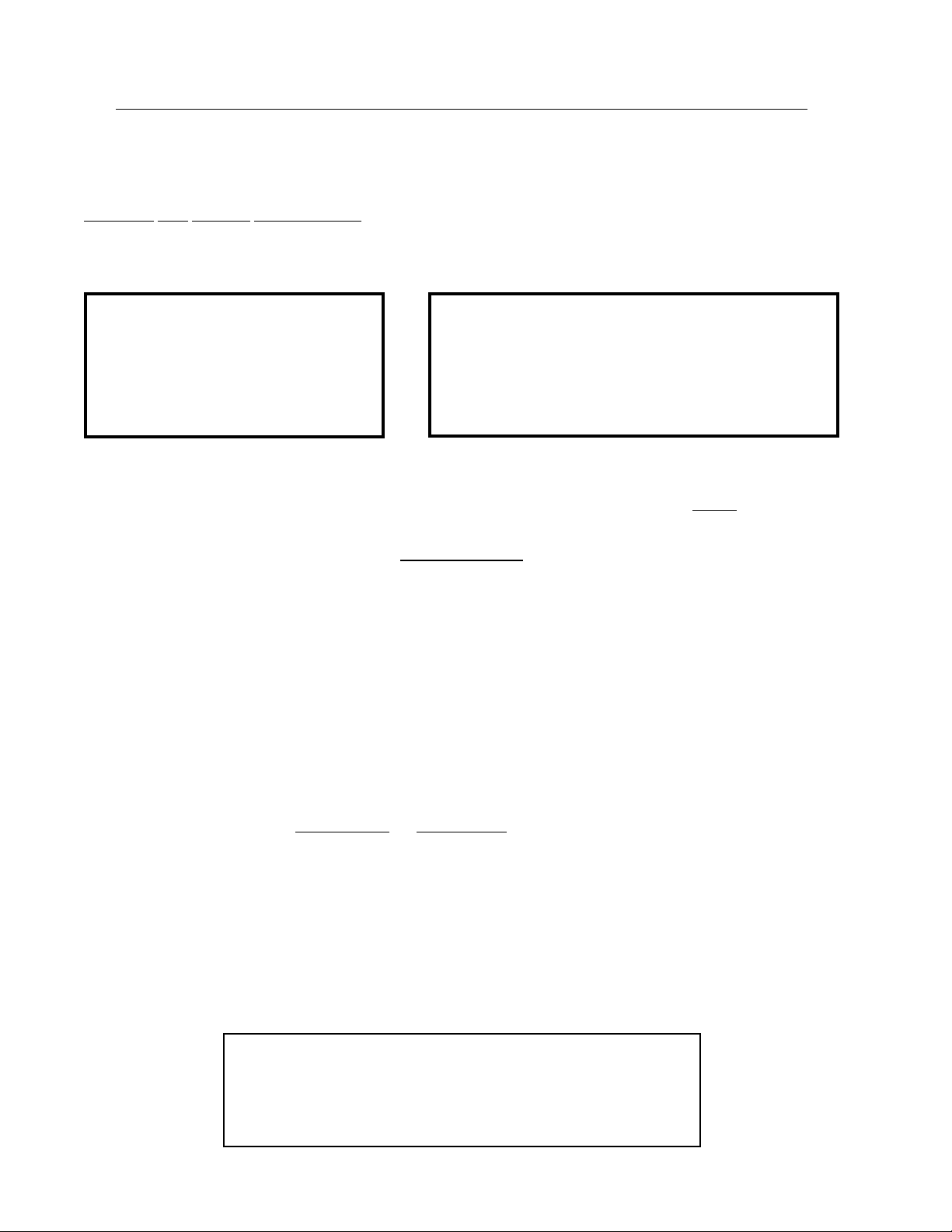
“IMPORTANTNOTETOPURCHASER”
Informationmustbeobtained from your local gas supplieron
the instructions to be followed if the user smells gas. These
instructionsmustbepostedinaprominentlocationnearthedryer.
FOR YOUR SAFETY
Do not store or use gasoline
or other flammable vapors
and liquids in the vicinity of
this or any other appliance.
POUR VOTRE SÉCURITÉ
Ne pas entreposer ni utiliser d’essence
ni d’autres vapeurs ou liquides
inflammables à proximité de cet appareil
ou de tout autre appareil.

In the State of Massachusetts, the following installation instructions apply:
■Installations and repairs must be performed by a qualified or licensed contractor,
plumber, or gas fitter qualified or licensed by the State of Massachusetts.
■Acceptable Shut-off Devices: Gas Cocks and Ball Valves installed for use shall be
listed.
■A flexible gas connector, when used, must not exceed 4 feet (121.9 cm).
IMPORTANT
YOUMUSTDISCONNECTANDLOCKOUTTHEELECTRICSUPPLYANDTHEGAS
SUPPLY OR THE STEAM SUPPLY BEFORE ANY COVERS OR GUARDS ARE
REMOVED FROM THE MACHINE TO ALLOW ACCESS FOR CLEANING,
ADJUSTING, INSTALLATION, OR TESTING OFANY EQUIPMENT PER OSHA
(OccupationalSafety andHealthAdministration)STANDARDS.
CHILDRENSHOULDNOTBEALLOWEDTOPLAYONORNEARTHEDRYER(S).
WARNING
CHILDRENSHOULDBESUPERVISEDIFNEARDRYER(S)INOPERATION.
DRYER(S)SHOULDNEVERBELEFTUNATTENDEDWHILEINOPERATION.
CAUTION
Caution: Label all wires prior to
disconnection when servicing
controls.Wiringerrorscancause
improper operation.
Attention: Au moment de l’entretien des
commandes, étiquetez tous les fils avant de les
débrancher. Des erreurs de câblage peuvent
entraînerunfonctionnement inadéquat.

IMPORTANT
PLEASEOBSERVEALLSAFETYPRECAUTIONSdisplayedontheequipmentand/or
specified in the installation manual included with the dryer.
The dryer must notbe installed or stored in an area where it will be exposed to water and/or
weather.
The wiring diagram for the dryer is located in the front electrical control box area.
WARNING
UNDER NO CIRCUMSTANCES should the dryer door switch or the heat circuit
devices ever be disabled.
DONOTMODIFYTHISAPPLIANCE.
The dryer must never be operated with any of the back guards, outer tops, or service
panelsremoved. PERSONALINJURYORFIRECOULDRESULT.
DRYERMUSTNEVERBEOPERATEDWITHOUTTHELINTFILTER/SCREENIN
PLACE,EVENIFANEXTERNALLINTCOLLECTIONSYSTEMISUSED.
If the hi-limit switch trips, a service call is required to investigate the reason and
resolve the issue.
FORYOURSAFETY
DONOTDRYMOPHEADSINTHE DRYER.
DONOTUSEDRYERINTHE PRESENCEOFDRYCLEANINGFUMES.

Table of Contents
SECTION I
IMPORTANT INFORMATION...............................................................................3
A. ReceivingandHandling ............................................................................................................... 3
B. SafetyPrecautions ...................................................................................................................... 4
SECTION II
SPECIFICATIONS ....................................................................................................7
A. Specifications ............................................................................................................................. 7
SECTION III
INSTALLATION PROCEDURES ...........................................................................9
A. Unpacking/ SettingUp ............................................................................................................... 9
B. LocationRequirements ............................................................................................................. 10
C. DryerEnclosureRequirements .................................................................................................. 11
D. FreshAirSupplyRequirements ................................................................................................. 12
E. ExhaustRequirements ............................................................................................................... 13
F. ElectricalInformation ................................................................................................................ 18
G. GasInformation ........................................................................................................................ 24
H. SteamInformation .................................................................................................................... 28
I. PreparationFor Operation / Start-Up ....................................................................................... 33
J. PreoperationalTest ................................................................................................................... 34
K. PreoperationalInstructions ........................................................................................................ 35
L. ShutDownInstructions ............................................................................................................. 38
SECTION IV
SERVICE / PARTS INFORMATION....................................................................39
A. Service ..................................................................................................................................... 39
B. Parts ........................................................................................................................................ 39
SECTION V
WARRANTY INFORMATION ..............................................................................40
A. ReturningWarrantyCards......................................................................................................... 40
B. Warranty .................................................................................................................................. 40
C. ReturningWarrantyParts .......................................................................................................... 40

SECTION VI
ROUTINE MAINTENANCE..................................................................................42
A. Cleaning ................................................................................................................................... 42
B. Adjustments ............................................................................................................................. 43
C. Lubrication ............................................................................................................................... 43
SECTION VII
TROUBLESHOOTING...........................................................................................44
MicroprocessorController (Computer) Models .............................................................................. 44
DualTimerModels ......................................................................................................................... 50
SECTION VIII
DATA LABEL INFORMATION.............................................................................54
SECTION IX
REVERSING TIMER SPIN / DWELL ADJUSTMENTS ..................................55
SECTION X
PROCEDURE FOR FUNCTIONAL CHECK
OF REPLACEMENT COMPONENTS................................................................56
SECTION XI
BURNER AND TUMBLER / LINT CHAMBER
MANUAL RESET HI-LIMIT INSTRUCTIONS .................................................58
GasModels Only ........................................................................................................................... 58
Electricor Steam ModelsOnly ....................................................................................................... 59

113063- 11 www.adclaundry.com 3
SECTIONI
IMPORTANTINFORMATION
A. RECEIVINGAND HANDLING
The dryer is shipped in a protective stretch wrap cover with protective cardboard corners and top cover (or
optional box) as a means of preventing damage in transit. Upon delivery, the dryer and packaging, and wooden
skid should be visually inspected for shipping damage. If any damage whatsoever is noticed, inspect further
before delivering carrier leaves.
Dryers damaged in shipment:
1. ALL dryers should be inspected upon receipt and before they are signed for.
2. If there is suspected damage or actual damage, the trucker’s receipt should be so noted.
3. If the dryer is damaged beyond repair, it should be refused. Those dryers, which were not damaged in a
damaged shipment, should be accepted, but the number received and the number refused must be noted
on the receipt.
4. If you determine that the dryer was damaged after the trucker has left your location, you should call the
delivering carrier’s freight terminal immediately and file a claim. The freight company considers this
concealed damage. This type of freight claim is very difficult to get paid and becomes extremely difficult
when more than a day or two passes after the freight was delivered. It is your responsibility to file freight
claims. Dryer/parts damaged in transit cannot be claimed under warranty.
5. Freight claims are the responsibility of the consignee, andALL claims must be filed at the receiving end.
ADC assumes no responsibility for freight claims or damages.
6. If you need assistance in handling the situation, please contact the ADC Traffic Manager at +1 (269)
923-3000.
IMPORTANT: The dryermustbetransportedandhandledinan upright position at ALLtimes.

4 American Dryer Corp. 113063-11
B. SAFETY PRECAUTIONS
WARNING: For yoursafety,the informationinthismanualmustbefollowedtominimize theriskof
fireor explosion or to preventpropertydamage,personalinjury,orloss of life.
WARNING: The dryer mustnever beoperated withany ofthe backguards, outertops, or
servicepanels removed. PERSONALINJURYOR FIRECOULD RESULT.
1. DO NOT store or use gasoline or other flammable vapors and liquids in the vicinity of this or any other
appliance.
2. DO NOT spray aerosols in the vicinity of this appliance while it is in operation
3. Purchaser/user should consult the local gas supplier for proper instructions to be followed in the event the
user smells gas. The instructions should be posted in a prominent location.
4. WHAT TO DO IF YOU SMELL GAS...
a. DO NOT try to light any appliance.
b. DO NOT touch any electrical switch.
c. DO NOT use any phone in your building.
d. Clear the room, building, or area of ALLoccupants.
e. Immediately call your gas supplier from a neighbor’s phone. Follow the gas supplier’s instructions.
f. If you cannot reach your gas supplier, call the fire department.
5. Installation and service must be performed by a qualified installer, service agency, or gas supplier.
6. Dryer(s) must be exhausted to the outdoors.
7. Although ADC produces a very versatile dryer, there are some articles that, due to fabric composition or
cleaning method, should not be dried in it.
WARNING: Dry only water washed fabrics. DO NOTdry articles spotted or washedin dry
cleaningsolvents,acombustibledetergent,industrialchemicals,or“allpurpose” cleaner.
EXPLOSIONCOULD RESULT.
WARNING: DO NOT dryragsorarticlescoatedorcontaminated with gasoline, kerosene, oil, paint,
orwax. EXPLOSIONCOULDRESULT.
WARNING: DO NOTdry mop heads. Contamination by waxorflammablesolventswillcreatea
firehazard.
WARNING: DO NOTuse heat for drying articles that contain plastic, foam, sponge rubber,or
similarlytexturedrubbermaterials. Drying inaheatedtumblermay damageplasticsor
rubberandmaybea fire hazard.

113063- 11 www.adclaundry.com 5
8. The possible presence of residual quantities of aggressive or decomposed chemicals in the load may produce
damage to the machine and harmful fumes.
9. A program should beestablished for the inspection and cleaning of lint in the burner area, exhaust ductwork,
and area around the back of the dryer. The frequency of inspection and cleaning can best be determined
from experience at each location.
WARNING: Thecollectionoflintin the burnerareaandexhaust ductwork can createapotentialfire
hazard.
10. For personal safety, the dryer must be electrically grounded in accordance with local codes and/or National
Electric Code ANSI/NFPA 70, or in Canada, Canadian Electric Code CSA C22.1.
NOTE: FailuretodosowillVOIDTHEWARRANTY.
11. UNDER NO CIRCUMSTANCES should the dryer door switch or the heat circuit devices ever be
disabled.
WARNING: PERSONALINJURYORFIRECOULDRESULT.
12. This dryer is not to be used in the presence of dry cleaning solvents or fumes.
13. Remove articles from the dryer as soon as the drying cycle has been completed.
WARNING: Articlesleftinthe dryerafterthedrying andcoolingcycles have beencompletedcan
createafirehazard.
14. READ AND FOLLOW ALL CAUTION AND DIRECTION LABELS ATTACHED TO THE DRYER.
15. For safety, proper operation, and optimum performance, the dryer must not be operated with a load less
than sixty-six percent (66%), 20 lb (9 kg) of its rated capacity.
WARNING: YOUMUSTDISCONNECTANDLOCKOUTTHEELECTRICSUPPLYAND
THEGASSUPPLYORTHESTEAMSUPPLYBEFOREANYCOVERSOR
GUARDSAREREMOVED FROMTHEMACHINETOALLOWACCESS
FORCLEANING,ADJUSTING,INSTALLATION,ORTESTINGOFANY
EQUIPMENTPEROSHA(Occupational SafetyandHealthAdministration)
STANDARDS.
IMPORTANT: Dryer mustbeinstalled in alocation/environment,whichtheambient
temperatureremainsbetween 40°F (4.44° C)and 130°F(54.44° C).
WARNING: Disconnect power beforeresetting thehi-limit. The hi-limit islocated onthe top
frontof thelint box. Pressand releaseand thehi-limit will reset.

6 American Dryer Corp. 113063-11
CE ONLY
IMPORTANT: This appliancemustonly beinstalledand operatedinthe countryofdestination
indicatedonthedryer’s data plate. If the appliance is to beinstalledandoperatedin a
countryotherthanthe one indicated on the data plate, a dataplateamendmentmust
beobtained fromAmerican Dryer Corporation.
IEC335 applies.
NOTES ____________________________________________________________________________________________________________________
___________________________________________________________________________________________________________________________
___________________________________________________________________________________________________________________________
___________________________________________________________________________________________________________________________
___________________________________________________________________________________________________________________________
___________________________________________________________________________________________________________________________
___________________________________________________________________________________________________________________________
___________________________________________________________________________________________________________________________
___________________________________________________________________________________________________________________________
___________________________________________________________________________________________________________________________
___________________________________________________________________________________________________________________________
___________________________________________________________________________________________________________________________
___________________________________________________________________________________________________________________________
___________________________________________________________________________________________________________________________
___________________________________________________________________________________________________________________________
___________________________________________________________________________________________________________________________
___________________________________________________________________________________________________________________________
___________________________________________________________________________________________________________________________
___________________________________________________________________________________________________________________________

113063- 11 www.adclaundry.com 7
MAXIMUM CAPACITY (DRY WEIGHT) 30 lb 13.6 kg
TUMBLER DIAMETER 30” 76.2 cm
TUMBLER DEPTH 30” 76.2 cm
TUMBLER VOLUME 12.3 cu ft 347.5 L
TUMBLER / DRIVE MOTOR 1/2 hp 0.373 kW
BLOWER / FAN MOTOR
N / A
DOOR OPENING (DIAMETER) 21-1/2” 54.6 cm
DOOR SILL HEIGHT 33-1/4” 84.5 cm
WATER CONNECTION 3/4-11.5 NH
(North America)
3/4” B.S.P.T.
(Outside North America)
DRYERS PER 20’/40’ CONTAINER 12 / 2 8
DRYERS PER 48’/53’ TRUCK 32 / 3 6
VOLTAGE AVAILABLE 120-480V 1,3ø 2,3,4w 50/60 Hz
APPROXIMATE NET WEIGHT 535 lb 242.7 kg
APPROXIMATE SHIPPING WEIGHT 585 lb 265.4 kg
AIRFLOW 60 Hz 600 cfm 17.0 cmm
50 Hz 500 cfm 14.2 cmm
HEAT INPUT 90,000 Btu/hr 22,680 kcal/hr
EXHAUST CONNECTION (DIAMETER) 8” 20.3 cm
INLET PIPE CONNECTION 1/2” M.N.P.T.
1/2” B.S.P.T.
(CE and Australia Only)
VOLTAGE AVAILABLE 208-480V 1,3ø 2,3,4w 50/60 Hz
APPROXIMATE NET WEIGHT 535 lb 242.7 kg
APPROXIMATE SHIPPING WEIGHT 585 lb 265.4 kg
AIRFLOW 60 Hz 460 cfm 13.0 cmm
50 Hz 383 cfm 10.8 cmm
EXHAUST CONNECTION (DIAMETER) 8” 20.3 cm
OVEN SIZE
kW Btu/hr kcal/hr
20 68,200 17,200
24 81,900 20,600
VOLTAGE AVAILABLE 120-480V 1,3ø 2,3,4w 50/60 Hz
APPROXIMATE NET WEIGHT 580 lb 263.1 kg
APPROXIMATE SHIPPING WEIGHT 630 lb 285.8 kg
AIRFLOW 60 Hz 600 cfm 17.0 cmm
50 Hz 500 cfm 14.2 cmm
STEAM CONSUMPTION 104 lb/hr 47.2 kg/hr
OPERATING STEAM PRESSURE 125 psi max 8.6 bar
EXHAUST CONNECTION (DIAMETER) 8” 20.3 cm
COMPRESSED AIR CONNECTION 1/8” F.N.P.T.
COMPRESSED AIR VOLUME 0.5 cfh 0.014 cmh
BOILER HORSEPOWER (NORMAL LOAD) 3.0 Bhp
SUPPLY CONNECTION 1” F.N.P.T.
RETURN CONNECTION 1” F.N.P. T.
SECTIONII
SPECIFICATIONS
A. SPECIFICATIONS
NOTE: ADCreservestherightto makechangesinspecifications atanytimewithout noticeor
obligation.
Shaded areas are stated in metric equivalents 5/7/14
* Specify air-operated or electromechanical steam damper system. Air-operated steam damper system must be
provided with clean, dry and regulated 80 psi ± 10 psi (5.51 bar ± 0.68 bar) air supply.
GAS
ELECTRICSTEAM*

8 American Dryer Corp. 113063-11
NOTE: ADCreservestherightto makechangesinspecifications atanytimewithout noticeor
obligation.
SPECIFICATIONS
ADG-30 ADE-30 ADS-30
MLG-30 MLE-30 MLS-30

113063- 11 www.adclaundry.com 9
SECTIONIII
INSTALLATIONPROCEDURES
Installation should be performed by competent professional in accordance with local, state, and country codes.
In the absence of these codes, the installation must conform to applicableAmerican National Standards: National
Fuel Gas CodeANSI Z223.1/NFPA54 and National Electric CodeANSI/NFPA70, or in Canada, the installation
must conform to applicable Canadian Standards: Natural Gas and Propane Installation Code CSA B149.1 and
Canadian Electric Code CSA C22.1.
A. UNPACKING / SETTING UP
Remove protective shipping material (i.e., plastic wrap and optional shipping box) from dryer.
IMPORTANT: Dryer mustbetransportedand handled inanuprightpositionat ALLtimes.
NOTE: ForOPL(non-coin)dryermodelsequippedwithlocks,thelockusedisadummylockandno
keyissuppliedorneeded. Thelock can be turned with any key,a screwdriver, a small coin,
orany small sharp object. For coin-operated dryers, the MK-100 (master key forboth the
controldoorand lint door) shouldbe made accessible because it willbeneeded throughout
variousphasesinthe installationofthedryer.
The dryer can be moved to its final location while still attached to the skid or with the skid removed. To un-skid
the dryer, locate and remove the four (4) bolts securing the base of the dryer to the wooden skid. Two (2) are
at the rear base (remove the back panel for access), and two (2) are located in the bottom of the lint chamber.
To remove the two (2) bolts located in the lint chamber area, remove the lint door.
With the skid removed, to make it easier to slide the dryer into its final position, slightly lower ALL four (4)
leveling legs, so that the dryer will slide on the legs instead of the base frame.
To increase bearing life and improve efficiency, the dryer should be tilted slightly to the rear.
The lint coops of ALL model dryers are supported during shipping by a bracket. REMOVE THIS BRACKET
BEFORE STARTING THE DRYER.
1. Leveling Dryer
The dryer is equipped with four (4) leveling legs, one (1) at each corner of the base. Two (2) are located
at the rear of the dryer base, and two (2) are located in the lint chamber (coop). To increase bearing life
and improve efficiency, the dryer should be tilted slightly to the rear.

10 American Dryer Corp. 113063-11
B. LOCATION REQUIREMENTS
Before installing the dryer, ensure the location conforms to local codes and ordinances. In the absence of such
codes or ordinances the location must conform with National Fuel Gas Code ANSI Z223.1/NFPA 54, or in
Canada, the installation must conform to applicable Canadian Standards: Natural Gas and Propane Installation
Code CSA B149.1.
1. The dryer must be installed on a sound level floor capable of supporting its weight. Carpeting must be
removed from the floor area that the dryer is to rest on.
IMPORTANT: “The dryermustbeinstalledonnoncombustiblefloorsonly.”
2. The dryer must not be installed or stored in an area where it will be exposed to water and/or weather.
3. The dryer is for use in noncombustible locations.
4. Provisions for adequate air supply must be provided as noted in this manual (refer to Fresh Air Supply
Requirements in Section D).
5. Clearance provisions mustbe made from combustible construction as noted in this manual (refer to Dryer
Enclosure Requirements in Section C).
6. Provisions must be made for adequate clearances for servicing and for operation as noted in this manual
(refer to Dryer Enclosure Requirements in Section C).
7. Dryer must be exhausted to the outdoors as noted in this manual (refer to Exhaust Requirements in
Section E).
8. Dryer must be located in an area where correct exhaust venting can be achieved as noted in this manual
(refer to Exhaust Requirements in Section E).
IMPORTANT: Dryer shouldbelocated whereaminimumamountofexhaust duct willbe necessary.
9. The dryer must be installed with a proper exhaust duct connection to the outside.
10. The dryer must be installed with provisions for adequate combustion and make-up air supply.
CAUTION: Thisdryerproducescombustiblelintandmustbeexhaustedtotheoutdoors. Every6
months,inspecttheexhaust ductingandremoveanylintbuildup.
IMPORTANT: Dryer mustbeinstalled in alocation/environment,whichtheambient
temperatureremainsbetween 40°F (4.44° C)and 130°F(54.44° C).

113063- 11 www.adclaundry.com 11
C. DRYER ENCLOSURE REQUIREMENTS
Bulkheads and partitions should be made of noncombustible materials and must be located a minimum of
12-inches (30.48 cm) above the dryer’s outer top; 18-inches (45.72 cm) for steam dryers, except along the front
of the dryer, which may be closed if desired.
NOTE: Allowancesmustbemadeforopeningthecontroldoor.
X = 12-inch (30.48 cm) minimum, 24-inches (60.96 cm) is suggested for ease of maintenance.
* 1-inch (2.54 cm) maximum for electric dryers.
** 18-inch (45.72 cm) minimum for steam dryers.
NOTE: Airconsiderations areimportantforproper andefficientoperation.
Dryers may be positioned sidewall to sidewall. However, a 1/16” (1.5875 mm) minimum allowance must be
made for the opening and closing of the control door and the lint door. It is suggested that the dryer be positioned
about 2 feet (0.61 meters) away from the nearest obstruction for ease of installation, maintenance, and service
(to be measured from the back guard). Refer to the illustration above for details.

12 American Dryer Corp. 113063-11
D. FRESH AIR SUPPLYREQUIREMENTS
This appliance may only be installed in a room that meets the appropriate ventilation requirements specified in
the national installation regulations.
The air supply (make-up air) must be given careful consideration to assure proper performance of each dryer.
An unrestricted source of air is necessary for each dryer. As a general rule, an unrestricted air entrance from
the outdoors (atmosphere) of a minimum of 1-1/2 square feet (0.14 square meters) is required for each dryer. If
registers or louvers are installed over the openings, then the area must be increased. It is not necessary to have
a separate make-up air opening for each dryer. Common make-up air openings are acceptable. However, they
must be set up in such a manner that the make-up air is distributed equally to the dryers. The dryer must be
installed with provisions for adequate combustion and make-up air supply.
EXAMPLE: For a bank of eight (8) dryers, two (2) unrestricted openings measuring 2 feet
by 3 feet (0.61 meters by 0.91 meters), (6 square feet [0.56 square meters]) are acceptable.
IMPORTANT: Make-up air openingsshouldnotbelocated in an areadirectly near where exhaust
ventsexitthebuilding.
Allowances must be made for remote or constricting passageways or where dryers are located at excessive
altitudes or predominantly low pressure areas.
IMPORTANT: Make-up air mustbeprovided from a source free ofdrycleaningsolventfumes.
Make-upairthatiscontaminatedby drycleaningsolventfumeswillresultin
irreparabledamagetothemotorsandother dryer components.
NOTE: Componentfailuredueto drycleaningsolventfumeswillVOIDTHEWARRANTY.

113063- 11 www.adclaundry.com 13
E. EXHAUST REQUIREMENTS
Exhaust ductwork shouldbedesigned and installed by a qualified professional. Improperly sized ductwork will
create excessive back pressure which results in slow drying, increased use of energy, and shutdown of the
burner by the airflow (sail) switch, burner hi-limit, or lint chamber hi-heat protector thermostat. The dryer must
be installed with a proper exhaust duct connection to the outside.
The design of the flue system shall be such that any condensate formed when operating the appliance from cold
shall either be retained and subsequently re-evaporated or discharged.
CAUTION: Thisdryerproducescombustiblelintandmustbeexhausted to the outdoors.
Where possible, it is suggested to provide a separate (single) exhaust duct for each dryer.
CAUTION: IMPROPERLYSIZEDORINSTALLEDEXHAUSTDUCTWORK CAN
CREATEAPOTENTIALFIREHAZARD.
CAUTION: DRYER MUST BEEXHAUSTEDTOTHE OUTDOORS.
The exhaust ductwork should be laid out in such a way that the ductwork travels as directly as possible to the
outdoors with as few turns as possible. The shape of the ductwork is not critical so long as the minimum cross
section area is provided. Single or independent dryer venting is recommended.
It is suggested that the use of 90° turns be avoided; use 30° or 45° angles instead.
The ductwork should be smooth inside with no projections from sheet metal screws or other obstructions,
which will collect lint. When adding ducts, the ducts to be added should overlap the duct to which it is connected.
ALL ductwork joints must be taped to prevent moisture and lint from escaping into the building. Additionally,
inspection doors should be installed at strategic points in the exhaust ductwork for periodic inspection and
cleaning.
IMPORTANT: When connecting ductwork to the dryer exhaust duct, be surethatwhenscrewsare
usedtheyDONOTrestrict the operation (both opening and closing) of the damper.
NOTE: Whenthe exhaust ductworkpassesthrougha wall,ceiling,orroof made ofcombustible
materials,theopeningmustbe2-inches(5.08cm)larger than the duct (all the way around).
Theduct mustbecenteredwithinthis opening.
To protect the outside end of the horizontal ductwork from the weather, a 90° elbow bent downward should be
installed where the exhaust exits the building. If the ductwork travels vertically up through the roof, it should be
protected from the weather by using a 180° turn to point the opening downward. In either case, allow at least
twice the diameter of the duct between the duct opening and the nearest obstruction (i.e., roof or ground level).
IMPORTANT: DO NOT usescreens, louvers, or caps ontheoutside opening of the exhaust
ductwork.
IMPORTANT: Exhaust backpressuremeasured byamanometer/magnehelic intheexhaustduct
mustbe no less than 0 and mustnot exceed0.3 inch water column (0.74 mb).

14 American Dryer Corp. 113063-11
NOTE: Itis recommendedthat exhaust or booster fans not be usedintheexhaustductwork system
exceptwherenecessary to maintain exhaust backpressure(intheexhaustduct)between zero
and0.3inchwatercolumn. Whereemployed,boosterfansmustnotactivatethe dryer
airflowproving switch(sailswitch)when thedryerisnotinoperation.
SINGLEDRYERVENTING
IMPORTANT: For exhaust duct runs over 30 feet (9.14 meters)aminimumsizeof10-inches(25.4
cm) must be used.
HORIZONTAL VENTING
When horizontal single 8-inch (20.32 cm) venting is used, the ductwork to the outlet cannotexceed 30 feet (9.14
meters), refer to Illus.A below. This calculation of 30 feet (9.14 meters) compensates or allows for the use of
a maximum of only one (1) elbow.
Illus. A

113063- 11 www.adclaundry.com 15
VERTICAL VENTING
When vertical single venting is used, the minimum duct size is 10-inches (25.4 cm) refer to Illus. B below, the
ductwork from the dryer to the outside outlet cannot exceed 60 feet (18.29 meters), refer to Illus. B below.
This calculation compensates for the use of a maximum of three (3) elbows including the two (2) elbows
creating the 180° (turned downward) outside outlet.
Illus. B
If the length of the duct run or quantity of elbows used exceeds the above noted specifications, the cross section
area of the ductwork must be increased in proportion to the number of elbows or duct run added.
IMPORTANT:For extended ductwork runs,thecross section area of the duct canonlybe increased
toanextent. For extended ductwork runs, aprofessionalheating,venting,andair
conditioning(HVAC)firmshouldbeconsultedfor properventinginformation.

16 American Dryer Corp. 113063-11
MULTIPLE DRYER (COMMON) VENTING
HORIZONTAL VENTING
If it is not feasible to provide separate exhaust ducts for each dryer, ducts for individual dryers may be channeled
into a common main duct. Each dryer is provided with a back draft damper. The individual ducts should enter
the bottom or side of the main duct at an angle not more than 45° in the direction of the airflow. No more than
four (4) dryers should be connected to one (1) main common duct run.
The main common duct may be any shape so long as the minimum cross-sectional area is provided. The main
duct should be tapered with the diameter increasing before each individual 8-inch (20.32 cm) duct is added
(refer to Illus. C and Illus. D).
Illus. C
Horizontal venting must not exceed 20 feet (6.1 meters) – this calculation compensates for the use of a
maximum of only one (1) elbow, which is the outside outlet protection.
NOTE: Distancebetweendryersingle ducts being connected to the main common ductmustbea
minimumof 31-3/8”(79.69cm) dryerwidth.
Ductwork shouldbelaid out in such amannerwhere allowances are made at reararea of the
dryerforremovalof rear service panels or guards.
Illus. C shows the minimum cross section area for horizontal multiple dryer venting. These figures must be
increased in proportion if the main duct run from the last dryer to where it exhausts has numerous elbows or is
unusuallylong.
This manual suits for next models
1
Table of contents
Other ADC Dryer manuals