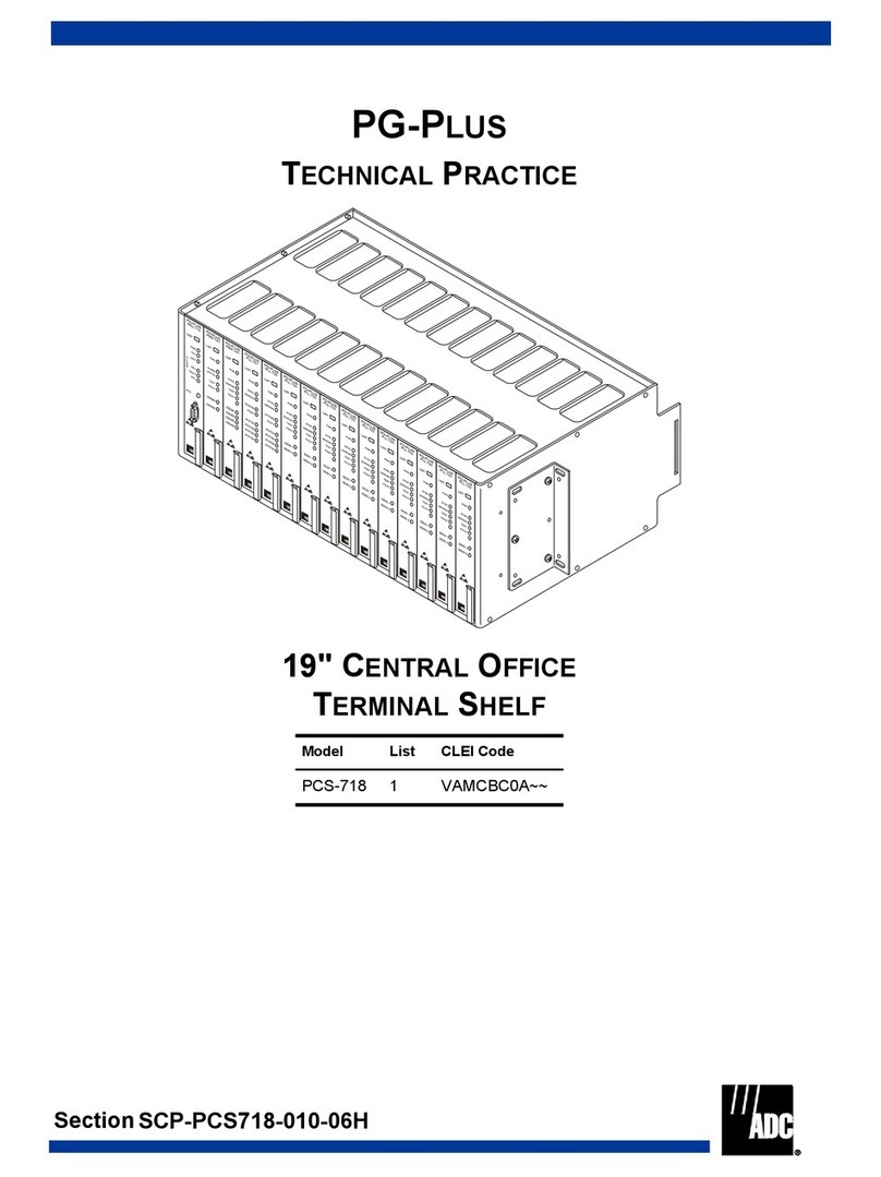
ADC HiGain HMS-317 List 2 User manual

INSTALLATIONGUIDE
Model/List Part Number CLEI
HMS-317 List 2 150-1128-02 T1MFUR04
HMS-317 List 3 150-1128-03 T1MF1R04
HMS-318 List 2 150-1129-02 T1MFVS04
HMS-318 List 2B 150-1129-22 N/A
HMS-317 AND HMS-318
MANAGEMENT SHELF
HMS-317
HMS-318

Revision History of This Guide LTPH-UG-1166-01
ii July 15, 2002 HMS-317 and HMS-318
REVISION HISTORY OF THIS GUIDE
This guide and other ADC publications can be downloaded from the ADC website at www.adc.com.
Copyright
July 15, 2002
©2002 ADC DSL Systems, Inc. All rights reserved.
Trademark Information
ADC is a registered trademark of ADC Telecommunications, Inc. HiGain is a registered trademark of ADC DSL Systems, Inc. No
right, license, or interest to such trademarks is granted hereunder, and you agree that no such right, license, or interest shall be
asserted by you with respect to such trademark.
Other product names mentioned in this practice are used for identification purposes only and may be trademarks or registered
trademarks of their respective companies.
Disclaimer of Liability
Information contained in this document is company private to ADC DSL Systems, Inc., and shall not be modified, used, copied,
reproduced or disclosed in whole or in part without the written consent of ADC.
Contents herein are current as of the date of publication. ADC reserves the right to change the contents without prior notice. In no
event shall ADC be liable for any damages resulting from loss ofdata, loss of use,or loss of profits, and ADC further disclaims any
and all liability for indirect, incidental, special, consequential or other similar damages. This disclaimer of liability applies to all
products, publications and services during and after the warranty period.
Issue Release Date Revisions Made
01 July 15, 2002 Initial release

LTPH-UG-1166-01 Using This Guide
HMS-317 and HMS-318 July 15, 2002 iii
USING THIS GUIDE
Two types of messages, identified by icons, appear in the text.
UNPACK AND INSPECT YOUR SHIPMENT
Upon receipt of the equipment:
•Unpack each container and inspect the contents for signs of damage. If the equipment has been damaged in
transit, immediately report the extent of damage to the transportation company and to ADC DSL Systems,
Inc. Order replacement equipment, if necessary.
•Check the packing list to ensure complete and accurate shipment of each listed item. If the shipment is short
or irregular, contact ADC DSL Systems, Inc. as described in “Appendix D - Product Support” on page 28. If
you must store the equipment for a prolonged period, store the equipment in its original container.
Notes contains information about special circumstances.
Cautions indicate the possibility of personal injury or
equipment damage.

Unpack and Inspect Your Shipment LTPH-UG-1166-01
iv July 15, 2002 HMS-317 and HMS-318

LTPH-UG-1166-01 Table of Contents
HMS-317 and HMS-318 July 15, 2002 v
TABLE OF CONTENTS
Overview ____________________________________________________________________________ 1
Description.........................................................................................................................................1
DSX-1 and HDSL Span Connectors ...................................................................................3
Power and Alarm Connections ..........................................................................................................4
Input Power Terminal Block ...............................................................................................4
Alarms Terminal Block .......................................................................................................5
Connecting to HDSL Circuits............................................................................................................6
DSX-1 and HDSL Plug-in Connections..............................................................................6
DSX-1 and HDSL Wire-wrap Connections ........................................................................6
Connecting to HDSL2 Circuits..........................................................................................................7
HDSL2 Plug-in Connections...............................................................................................7
HDSL2 Wire-wrap Connections .........................................................................................7
Connecting to HDSL4 Circuits..........................................................................................................8
HDSL4 Plug-in Connections...............................................................................................8
HDSL4 Wire-wrap Connections .........................................................................................8
Connecting G.703 Circuits to the HMS-318......................................................................................9
G.703 Plug-in Connections..................................................................................................9
G.703 Wire-wrap Connections..........................................................................................10
Asynchronous Management Ports ...................................................................................................13
Multishelf Network Connections.....................................................................................................14
Power Dissipation Factors ...............................................................................................................15
Installation__________________________________________________________________________ 16
Site Requirements............................................................................................................................16
Shelf Installation..............................................................................................................................16
Appendix A - Signal and Pin Assignments________________________________________________ 18
Connector P1 - DSX Receive............................................................................................18
Connector P2 - DSX Transmit...........................................................................................20
Connector P3 (Loop 1) ......................................................................................................22
Connector P4 (Loop 2) ......................................................................................................24
Appendix B - Standard PIC Color Code _________________________________________________ 26
Appendix C - Specifications____________________________________________________________ 27
Appendix D - Product Support _________________________________________________________ 28
Appendix E - Abbreviations ___________________________________________________________ 29
Certification and Warranty____________________________________________________________ 31

LTPH-UG-1166-01 List of Figures
HMS-317 and HMS-318 July 15, 2002 vii
LIST OF FIGURES
1. HMS-317 and HMS-318 Front View............................................................................................................1
2. HMS-317 and HMS-318 Rear View.............................................................................................................2
3. Input Power Terminal Block (TB1)...............................................................................................................4
4. Alarms Terminal Block (TB2) ......................................................................................................................5
5. HLU Slot Wire-wrap Pinouts for HDSL Circuits .........................................................................................6
6. HLU Slot Wire-wrap Pinouts for HDSL2 Circuits .......................................................................................7
7. HLU Slot Wire-wrap Pinouts for HDSL4 Circuits .......................................................................................8
8. ADC HCP-322 List 1 and List 2 Connector Panel........................................................................................9
9. Typical HiGain G.703 Application ...............................................................................................................9
10. HLU Slot Wire-wrap Pinouts for G.703/HDSL Circuits ............................................................................10
11. HLU Slot Wire-wrap Pinouts for G.703/HDSL2 Circuits ..........................................................................11
12. HLU Slot Wire-wrap Pinouts for G.703/HDSL4 Circuits ..........................................................................12
13. HMS OS and AUX Asynchronous Management Ports...............................................................................13
14. Multishelf Network Ports............................................................................................................................14
15. Central Office Equipment Rack Configuration...........................................................................................15
16. Input Power Terminal Strip (TB1) ..............................................................................................................17
17. Terminal Strip TB2, HMU-319 Alarm Outputs..........................................................................................17

LTPH-UG-1166-01 List of Tables
HMS-317 and HMS-318 July 15, 2002 ix
LIST OF TABLES
1. HMS Backplane Connections........................................................................................................................3
2. J30/J24 - OS RS-232 PORT (DTE).............................................................................................................13
3. J31/J25 - AUX RS-232 PORT (DTE).........................................................................................................14
4. P1-DSX Receive, Tip and Ring...................................................................................................................18
5. P2-DSX Transmit, Tip and Ring.................................................................................................................20
6. P3-HDSL Loop 1, Tip and Ring..................................................................................................................22
7. P4-HDSL Loop 2, Tip and Ring..................................................................................................................24
8. Standard PIC Color Code............................................................................................................................26

List of Tables LTPH-UG-1166-01
x July 15, 2002 HMS-317 and HMS-318

LTPH-UG-1166-01 Overview
HMS-317 and HMS-318 July 15, 2002 1
OVERVIEW
This guide provides detailed information and installation instructions for the following HiGain®Central Office
(CO) Management shelves:
•HMS-317 List 2
•HMS-317 List 3
•HMS-318 List 2
•HMS-318 List 2B
DESCRIPTION
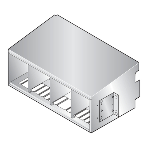
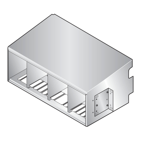
The HMS-317 and HMS-318 shelves (Figure 1) support 1.544 Mpbs (T1) or 2.048 Mpbs (E1) full-duplex
transmission over two unconditioned, non-loaded copper loops. Each shelf supports DSX-1 interfaces at the
central office (CO) and the remote end, with remote provisioning and performance monitoring. In addition, the
HMS-318 supports G.703 circuit connections.
HMS-317 and HMS-318 shelves are shipped with:
•Adjustable mounting brackets that allow the shelf to be positioned in the equipment rack to match the recess
of existing equipment.
•M5 x 0.8 by 10 mm mounting screws (4)
•BNC-T connector
•50WBNC terminator
•HMS-317 and HMS-318 Management Shelf Quick Installation Guide
.
Figure 1. HMS-317 and HMS-318 Front View
HMS-317
HMS-318
23" (58.42 cm)
19" (48.26 cm)
HLU1-HLU28
HLU1-HLU22
5.22"
(13.26 cm)
HMU
HMU
5.22"
(13.26 cm)

Overview LTPH-UG-1166-01
2 July 15, 2002 HMS-317 and HMS-318
The HMS-317 (List 2 and List 3) shelf has one HMU and 28 HLU card slots. The HMS-318 (List 2 and List 2B)
shelf has one HMU and 22 HLU card slots. Communications between the HMU slot and the HLU card slots are
routed through the backplane.
Figure 2 shows the location of the connectors, wire-wrap pins and terminal boards located on the backplane ofthe
HMS-317 and HMS-318 shelves. Table 1 provides a description of each backplane component. For information
on the signal and pin assignments for these connectors, see “Appendix A - Signal and Pin Assignments” on
page 18.
Figure 2. HMS-317 and HMS-318 Rear View
TB2
TB2
HMS-317
HMS-318
J32 J34 J31 Connector (P1)Connector (P2)
Connector (P4)Connector (P3)
J30 Input Power
Terminal Board
(TB1)
Alarms Terminal
Board (TB2)
J26 J34 J25 Connector (P1)Connector (P2)
Alarms Terminal
Board (TB2)
Connector (P4)
Connector (P3) Input Power
Terminal Board
(TB1)
J24
AUX Rs232 PORT XMT FROM DSX RCV TO DSX
HDSL LOOP 1 (XMT TO SPAN) HDSL LOOP 2 (RCV FROM SPAN)
OS Rs232 PORT
XMT FROM DSX RCV TO DSX
HDSL LOOP 1 (XMT TO SPAN) HDSL LOOP 2 (RCV FROM SPAN)
OS Rs232 PORT

LTPH-UG-1166-01 Overview
HMS-317 and HMS-318 July 15, 2002 3
DSX-1 and HDSL Span Connectors
Figure 2 on page 2 shows the location of the HDSL span connectors on the backplane of the HMS-317 and
HMS-318 shelves. For information on the signal and pin assignments for these connectors, see “Appendix A -
Signal and Pin Assignments” on page 18.
HMS-317 List 2 and List 3 Plug-in Connectors
The HMS-317 List 2 and List 3 (Figure 2 on page 2) have two 64-pin Amphenol-type male connectors (P1 and
P2) for DSX-1 receive and transmit connections and two 64-pin Amphenol-type male connectors (P3 and P4) on
the backplane. These connectors provide HDSL Span, Loop1 and Loop 2, receive and transmit connections to the
shelf. These connectors provide Tip and Ring connections for all cards in the shelf. Use a mating 64-Pin AMP
Style RP No. 2-5522771 connector for 24–26 AWG cables or an RS No. 552307-1 for 22 AWG cables.
HMS-318 List 2 and List 2B Plug-in Connectors
The HMS-318 List 2 and List 2B (Figure 2 on page 2) have two 50-pin Amphenol-type male connectors (P1 and
P2) for DSX-1 receive and transmit connections and two 50-pin Amphenol-type male connectors (P3 and P4) on
the backplane. These connectors provide HDSL Span, Loop1 and Loop 2, receive and transmit connections to the
shelf. These connectors provide Tip and Ring connections for all cards in the shelf. Use a mating 50-pin AMP
Style Kit No. 2-22913-1 connector for 24–26 AWG cables.
Table 1. HMS Backplane Connections
Connector/Terminal Board
Connector Type Description
HMS-317
List 2 and 3
HMS-318
List 2 and 2B
J32 J26 BNC 10BASE-2 Ethernet LAN connector
J34 J34 RJ-45 10BASE-T Network Management port
J31 J25 RS-232 DB-25 (Female) AUX Craft Port (DTE)
J30 J24 RS-232 DB-25 (Female) OS Craft Port (DTE)
P1 —Amphenol 64-pin (Male) DSX-1 Receive
P2 —Amphenol 64-pin (Male) DSX-1 Transmit
P3 —Amphenol 64-pin (Male) HDSL Span Loop 1
P4 —Amphenol 64-pin (Male) HDSL Span Loop 2
—P1 Amphenol 50-pin (Male) DSX-1 Receive
—P2 Amphenol 50-pin (Male) DSX-1 Transmit
—P3 Amphenol 50-pin (Male) HDSL Span Loop 1
—P4 Amphenol 50-pin (Male) HDSL Span Loop 2
J1 - J28 J1 - J22 20-pin wire-wrap HLU connectors
J29 J23 DIN 96-pin (Female) HMU connector
TB1 —7-position terminal block Power connector
—TB1 9-position terminal block Power connector
TB2 TB2 22-pin wire-wrap Alarm connector

Overview LTPH-UG-1166-01
4 July 15, 2002 HMS-317 and HMS-318
POWER AND ALARM CONNECTIONS
Both the HMS-317 and HMS-318 have separate input power (TB1) and alarms (TB2) terminal boards. This
section provides detailed information on TB1 and TB2 connections to each shelf.
Input Power Terminal Block
The input power terminal board (TB1) provides a central connection point for the CO primary and redundant
(HMS-317 List 3 only) power feeds (A and B). Figure 3 illustrates TB1 on the HMS-317 and the HMS-318
shelves.
Figure 3. Input Power Terminal Block (TB1)
HMS-317 List 2 Input Power Connections
The power and fan inputs terminal block (TB1; see Figure 3) provides a central connection point for the CO
primary input power feed. Slots 1 through 14 on the HMS-317 List 2 are powered by the -48VA bus. Slots 15
through 28 are powered by the -48VB bus. The two GND terminals are tied together. The HMU-319 is
diode-OR’ed to both power busses, to guard against power failure in the event that one power supply is lost. This
feature requires the 2 ground terminals to be tied together on the HMU card.
HMS-317 List 3 Input Power Connections
The HMS-317 List 3 requires two battery supply sources (-48VA bus and -48VB bus). The power and fan inputs
terminal block (TB1; see Figure 3) provides a central connection point for the CO primary and redundant input
power feeds. The -48VA bus provides primary power to slots 1 through 28. The -48VB bus provides to ensure
backup power in the event of a power failure.
HMS-318 List 2 and 2B Input Power Connections
The power and fan inputs terminal block (TB1; see Figure 3) provides a central connection point for the CO
primary input power feed. Slots 1 through 11 on the HMS-318 List 2 and List 2B are powered by the -48VA bus.
Slots 12 through 22 are powered by the -48VB bus. The two GND terminals are tied together. The HMU-319 is
diode-OR’ed to both power busses, to guard against power failure in the event that one power supply is lost. This
feature requires the 2 ground terminals to be tied together on the HMU card.
-48VA
1234567
-48VB GND GND FG
FAN
TB1

LTPH-UG-1166-01 Overview
HMS-317 and HMS-318 July 15, 2002 5
Alarms Terminal Block
The Alarms Terminal Block (TB2; see Figure 4) is a 22-pin wire-wrap connector. TB1 provides a central
connection point to the Normally Closed (NC), Common (COM) and Normally Open (NO) relay contacts for
installing optional alarm inputs connections.
Figure 4. Alarms Terminal Block (TB2)
NC
C
NO
NC
C
NO
NC
C
NO
NC
C
NO
NC
C
NO
NC
C
NO
NC
C
NO
CRIT
AUD
CRIT
VIS
MAJ
AUD
MAJ
VIS
MIN
AUD
MIN
VIS
SYS
ID
ACO
1
2
3
4
5
6
7
8
9
10
11
12
13
14
15
16
17
18
19
20
21
22

Overview LTPH-UG-1166-01
6 July 15, 2002 HMS-317 and HMS-318
CONNECTING TO HDSL CIRCUITS
This section provides information on making DSX-1 and HDSL connections to HMS-317 and HMS-318 shelves.
DSX-1 and HDSL Plug-in Connections
DSX-1 connections to the HMS-317 and HMS-318 shelves can be made through HMS backplane connectors P1
(RCV to DSX) and P2 (XMT from DSX). HDSL connections to the shelves can be made through backplane
connectors P3 (HDSL Loop 1) and P4 (HDSL Loop 2). Connectors P1, P2, P3 and P4 are described in “DSX-1
and HDSL Span Connectors” on page 3.
DSX-1 and HDSL Wire-wrap Connections
DSX-1 and HDSL connections can be made to the individual card connectors through the HMS backplane
wire-wrap pins (0.045-inch square/1.14 mm). Straps for cable dressings and a protective Lexan rear cover are
provided with the shelf. Figure 5 shows the HLU card slot pinouts on the HMS backplane.
Figure 5. HLU Slot Wire-wrap Pinouts for HDSL Circuits
DS1 Transmit - Tip DS1 - RingTransmit
DS1 Receive -Tip DS1 RingReceive -
A
B
C
D
E
F
J
H
Error Alarm Bus Ground (GND)
HDSL Loop 1 - Tip
HDSL Loop 1- Receive
Minor Alarm
Loss Of Signal Alarm (LOS ALM) *
Management Bus
Frame Ground -48 Vdc Battery
HDSL Loop 2 - Transmit HDSL Loop 2 - Receive
FL (not used) Fuse Alarm **
1
2
3
4
5
6
7
8
9
10
K
L
** Fuse alarm is normally floating (0 to -80V maximum) and at -48V
(10 ma maximum) when activated
*Minor alarm output is normally floating (0 to -60V maximum) and a
ground (10 ma maximum, +5Vdc for HLU-319 List 2D) when activated
Notes:

LTPH-UG-1166-01 Overview
HMS-317 and HMS-318 July 15, 2002 7
CONNECTING TO HDSL2 CIRCUITS
This section provides information on making DSX-1 and HDSL2 connections to HMS-317 and HMS-318 shelves.
HDSL2 Plug-in Connections
DSX-1 connections to the HMS-317 and HMS-318 shelves can be made through HMS backplane connectors P1
(RCV to DSX) and P2 (XMT from DSX). HDSL2 connections to the shelves can be made through backplane
connectors P3 (HDSL Loop 1) and P4 (HDSL Loop 2). Connectors P1, P2, P3 and P4 are described in “DSX-1
and HDSL Span Connectors” on page 3.
HDSL2 Wire-wrap Connections
DSX-1 and HDSL2 connections can be made to the individual card connectors through the HMS backplane
wire-wrap pins (0.045-inch square/1.14 mm). Straps for cable dressings and a protective Lexan rear cover are
provided with the shelf. Figure 6 shows the HLU card slot pinouts on the HMS backplane.
Figure 6. HLU Slot Wire-wrap Pinouts for HDSL2 Circuits
DSX-1 (IN)Tip
DSX-1 Tip 1 (OUT)
A
B
C
D
E
F
J
H
Ground (GND)
HDSL2 Span Tip
HDSL2 Span Ring
System Alarm *
Management Bus *
Frame Ground -48 Vdc Battery
Factory use only Fuse Alarm **
1
2
3
4
5
6
7
8
9
10
K
L
** Fuse alarm normally floating (0 to -80 Vdc maximum)
and at -48Vdc (10 ma maximum) when activated.
*System alarm and management bus reserved.
Notes:
DSX-1 (IN)Ring
DSX-1 Ring 1 (OUT)

Overview LTPH-UG-1166-01
8 July 15, 2002 HMS-317 and HMS-318
CONNECTING TO HDSL4 CIRCUITS
This section provides information on making DSX-1 and HDSL4 connections to HMS-317 and HMS-318 shelves.
HDSL4 Plug-in Connections
DSX-1 connections to the HMS-317 and HMS-318 shelves can be made through HMS backplane connectors P1
(RCV to DSX) and P2 (XMT from DSX). HDSL4 connections to the shelves can be made through backplane
connectors P3 (HDSL Loop 1) and P4 (HDSL Loop 2). Connectors P1, P2, P3 and P4 are described in “DSX-1
and HDSL Span Connectors” on page 3.
HDSL4 Wire-wrap Connections
DSX-1 and HDSL2 connections can be made to the individual card connectors through backplane wire-wrap pins
(0.045-inch square/1.14 mm). Straps for cable dressings and a protective Lexan rear cover are provided with the
shelf. Figure 7 shows the HLU card slot pinouts on the HMS backplane.
Figure 7. HLU Slot Wire-wrap Pinouts for HDSL4 Circuits
DSX-1 (IN)Tip
DSX-1 Tip 1 (OUT)
A
B
C
D
E
F
J
H
Ground (GND)
HDSL4 Loop 1 Tip
HDSL4 Loop 1 Ring
System Alarm *
Management Bus *
Frame Ground -48 Vdc Battery
Factory use only Fuse Alarm **
1
2
3
4
5
6
7
8
9
10
K
L
** Fuse alarm normally floating (0 to -80 Vdc maximum)
and at -48Vdc (10 ma maximum) when activated.
*System alarm and management bus reserved.
Notes:
DSX-1 (IN)Ring
DSX-1 Ring 1 (OUT)
HDSL4 Loop 2 Tip
HDSL4 Loop 2 Ring

LTPH-UG-1166-01 Overview
HMS-317 and HMS-318 July 15, 2002 9
CONNECTING G.703 CIRCUITS TO THE HMS-318
The HiGain System provides a cost-effective, easy-to-deploy method for delivering G.703 High Capacity Digital
Service (HCDS) over metallic pairs. Customers can deploy fiber-like quality service over two unconditioned,
non-loadedcopperpairs withoutusing conventionalspanrepeatersor cable pairconditioning and without the need
to separate pairs or remove bridged taps.
G.703 Plug-in Connections
The ADC HCP-322 Connector Panel, List 1 and List 2 (Figure 8 on page 9), can be used to connect up to 22 G.703
circuits to HiGain ELU-319 line units housed in the HMS-318 shelf. The ADC HCP-322 List 1 panel has 44 BNC
connectors for connecting G.703 75Wcircuits to ELU-319 List 1, List 5 and 5D line units. The ADC HCP-322
List 2 panel contains 22 DB-15 connectors for connecting G.703 120Wcircuits to ELU-319 List 6 and 6D line
units. The ADC HCP-322 List 2 panel also includes wire-wrap pins for optionally connecting the connector case
of each receive (RCV) pair to frame ground. A typical application of the HCP-322 Connector Panel is shown in
Figure 9 on page 9.
Figure 8. ADC HCP-322 List 1 and List 2 Connector Panel
Figure 9. Typical HiGain G.703 Application
For more information on the ADC HCP-322 Connector Panel or installation instructions, refer to the HCP-322
Quick Installation Guide, document number 100-322-100-xx.
HCP-322 List 1 Connector Panel
HCP-322 List 2 Connector Panel

Overview LTPH-UG-1166-01
10 July 15, 2002 HMS-317 and HMS-318
G.703 Wire-wrap Connections
G.703 connections can be made to the individual card connectors through the HMS backplane wire-wrap pins
(0.045-inch square/1.14 mm). Straps for cable dressings and a protective Lexan rear cover are provided with the
shelf.
G.703 Wire-wrap Connections for HDSL
Figure 10 shows the HLU card slot pinouts on the HMS backplane for HDSL circuits.
Figure 10. HLU Slot Wire-wrap Pinouts for G.703/HDSL Circuits
G.703 Transmit - Tip
G.703 - RingTransmit
G.703 Receive -Tip G.703 RingReceive -
A
B
C
D
E
F
J
H
Error Alarm Bus Ground (GND)
HDSL Loop 1 - Tip
HDSL Loop 1- Receive
Minor Alarm
Loss Of Signal Alarm (LOS ALM) *
Management Bus
Frame Ground -48 Vdc Battery
HDSL Loop 2 - Transmit HDSL Loop 2 - Receive
FL (not used) Fuse Alarm **
1
2
3
4
5
6
7
8
9
10
K
L
** Fuse alarm is normally floating (0 to -80V maximum) and at -48V
(10 ma maximum) when activated
*Minor alarm output is normally floating (0 to -60V maximum) and a
ground (10 ma maximum, +5Vdc for HLU-319 List 2D) when activated
Notes:

LTPH-UG-1166-01 Overview
HMS-317 and HMS-318 July 15, 2002 11
G.703 Wire-wrap Connections for HDSL2
Figure 11 shows the HLU card slot pinouts on the HMS backplane for HDSL2 circuits.
Figure 11. HLU Slot Wire-wrap Pinouts for G.703/HDSL2 Circuits
G.703 (IN)Tip
G.703 Tip 1 (OUT)
A
B
C
D
E
F
J
H
Ground (GND)
HDSL2 Span Tip
HDSL2 Span Ring
System Alarm *
Management Bus *
Frame Ground -48 Vdc Battery
Factory use only Fuse Alarm **
1
2
3
4
5
6
7
8
9
10
K
L
** Fuse alarm normally floating (0 to -80 Vdc maximum)
and at -48Vdc (10 ma maximum) when activated.
*System alarm and management bus reserved.
Notes:
G.703 (IN)Ring
G.703 Ring 1 (OUT)

Overview LTPH-UG-1166-01
12 July 15, 2002 HMS-317 and HMS-318
G.703 Wire-wrap Connections for HDSL4
Figure 12 shows the HLU card slot pinouts on the HMS backplane for HDSL4 circuits.
Figure 12. HLU Slot Wire-wrap Pinouts for G.703/HDSL4 Circuits
G.703 Tip (IN)
G.703 Tip 1 (OUT)
A
B
C
D
E
F
J
H
Ground (GND)
HDSL4 Loop 1 Tip
HDSL4 Loop 1 Ring
System Alarm *
Management Bus *
Frame Ground -48 Vdc Battery
Factory use only Fuse Alarm **
1
2
3
4
5
6
7
8
9
10
K
L
** Fuse alarm normally floating (0 to -80 Vdc maximum)
and at -48Vdc (10 ma maximum) when activated.
*System alarm and management bus reserved.
Notes:
G.703 Ring (IN)
G.703 Ring 1 (OUT)
HDSL4 Loop 2 Tip
HDSL4 Loop 2 Ring
Other manuals for HiGain HMS-317 List 2
1
This manual suits for next models
1
Table of contents
Other ADC Indoor Furnishing manuals
Popular Indoor Furnishing manuals by other brands

RiverRidge
RiverRidge 06-188 Assembly instructions

Home Decorators Collection
Home Decorators Collection MT25CW Assembly instructions

Costway
Costway HW64005 user manual

porada
porada JOINT 120 C Assembly instruction

Forte
Forte Rayong RXGS82511 Assembling Instruction

SHANGRI-LA
SHANGRI-LA SERENGETI SLSERENDCWA user guide