ADC PG-PLUS PCS-718 Instructions for use

SCP-PCS718-020-04H
Section
PG-PLUS
TECHNICAL PRACTICE
19" CENTRAL OFFICE
TERMINAL SHELF
Model List CLEI Code
PCS-718 2S9MTBA0A~~

SCP-PCS718-020-04H
January 6, 2003 PCS-718 List 2
©Copyright 2003 ADC DSL Systems, Inc. All Rights Reserved.
ADC is a registered trademark of ADC Technologies, Inc. PG-Plus is a registered trademark of ADC DSL Systems, Inc. No right,
license, or interest to such trademarks is granted hereunder, and you agree that you shall assert no such right, license, or interest
with respect to such trademarks. Other product names mentioned in this document are used for identification purposes only and
may be trademarks or registered trademarks of their respective companies.
Information contained in this document is company private to ADC DSL Systems, Inc., and shall not be modified, used, copied,
reproduced or disclosed in whole or in part without the written consent of ADC.
Contents herein are current as of the date of publication. ADC reserves the right to change specifications at any time without notice.
Information furnished by ADC is believed to be accurate and reliable. In no event shall ADC be liable for any damages resulting
from the loss of data, loss of use, or loss of profits and ADC further disclaims any and all liability for indirect, incidental, special,
consequential or other similar damages. This disclaimer of liability applies to all products, publications and services during and
after the warranty period.
Revision History of This Practice
Revision Release Date Revisions Made
02 October 10,1997 Add wiring pin tables and correct connection process
03 January 10, 2002 Release to rebrand document to comply with ADC standards
04 January 6, 2003 Updated Product Support Information

SCP-PCS718-020-04H Using This Technical Practice
PCS-718 List 2 January 6, 2003
USING THIS TECHNICAL PRACTICE
Two types of messages, identified by icons, appear in the text:
Notes contain information about special circumstances.
Cautions indicate the possibility of equipment damage or the possibility of personal injury.

Using This Technical Practice SCP-PCS718-020-04H
January 6, 2003 PCS-718 List 2

SCP-PCS718-020-04H
PCS-718 List 2 January 6, 2003 i
TABLE OF CONTENTS
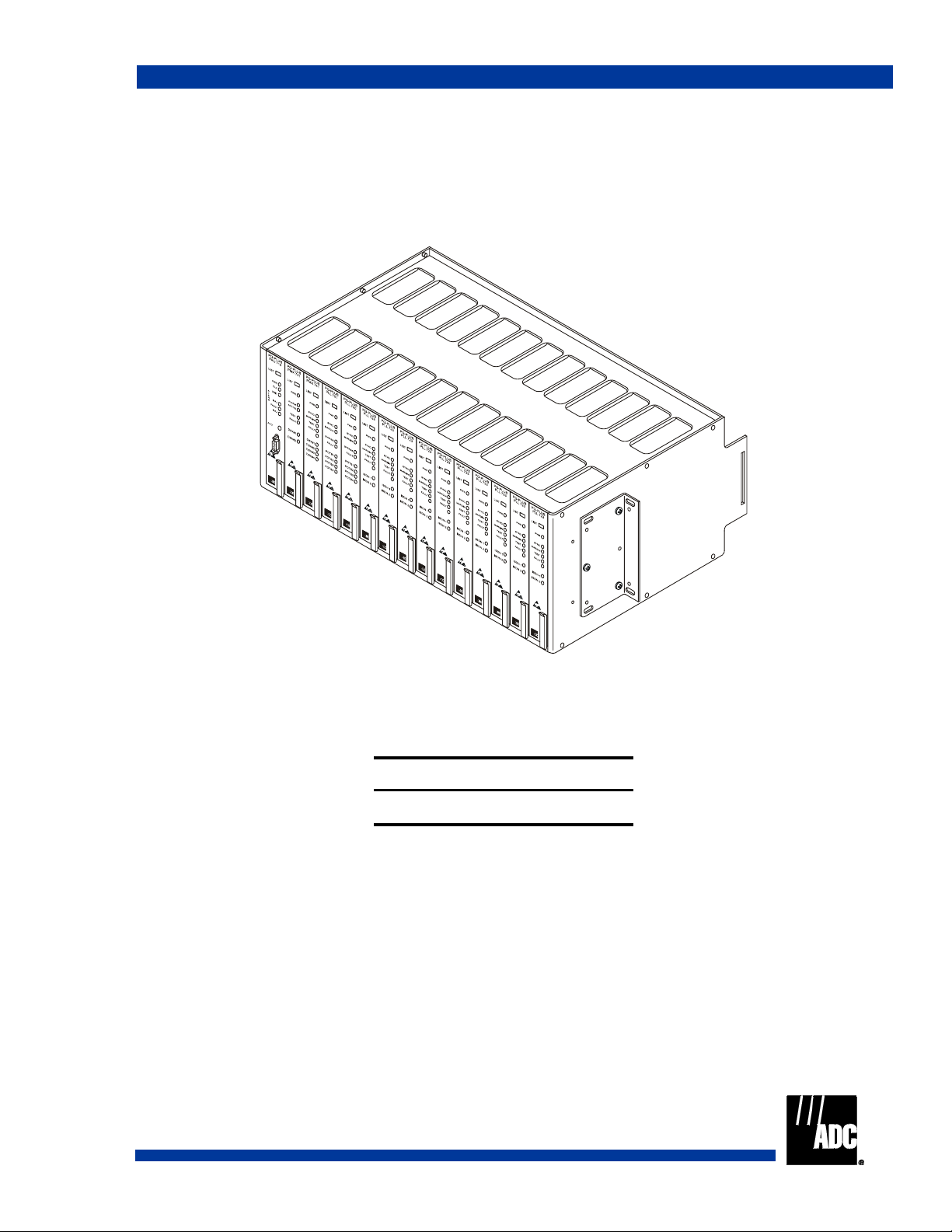
PCS-718 Overview ____________________________________________________________________ 1
Description and Features....................................................................................................................1
Theory of Operation...........................................................................................................................2
Data Channel Overview.......................................................................................................2
Serial Communications Bus ................................................................................................3
Composite Clock Signals.....................................................................................................3
Test Bus.................................................................................................................3
Communication Requests......................................................................................3
Backplane Connections .......................................................................................................3
COLU HDSL.........................................................................................................5
Two-Wire Subscriber Pairs ...................................................................................5
Four-Wire Pairs .....................................................................................................5
Alarm Cutoff......................................................................................................................17
Alarm Contacts ..................................................................................................................18
OS Interface.......................................................................................................................18
LAN Interface....................................................................................................................18
DSX1 Connections ............................................................................................................19
PAU/PMU Connector........................................................................................................19
PMX Connector.................................................................................................................20
Specifications ...................................................................................................................................22
Installation and Test__________________________________________________________________ 22
Required Tools and Test Equipment................................................................................................22
Power ...............................................................................................................................................23
Mounting..........................................................................................................................................23
Wiring Access ..................................................................................................................................23
Alarm Leads.....................................................................................................................................23
HDSL Lines .....................................................................................................................................23
Subscriber Lines...............................................................................................................................23
Connections......................................................................................................................................23
Ground Connections ..........................................................................................................23
Power Connections ............................................................................................................24
Redundant-Shelf Powering .................................................................................24
Split-Shelf Powering ...........................................................................................25
Single-Source Powering......................................................................................26
Audible and Visual Alarm Connections............................................................................27
Subscriber Connections From CO.....................................................................................29

SCP-PCS718-020-04H
ii January 6, 2003 PCS-718 List 2
Composite Clock Connections ......................................................................................... 34
HDSL Wiring .................................................................................................................... 35
External ACO Connection ................................................................................................ 37
Turn-Up and Test .............................................................................................................. 37
Product Support _____________________________________________________________________ 38
Technical Support............................................................................................................................ 38
Limited Warranty ............................................................................................................................ 38
Returns............................................................................................................................................. 38
FCC Class A Compliance................................................................................................................ 40
Modifications................................................................................................................................... 40
Acronyms___________________________________________________________________________ 41

SCP-PCS718-020-04H
FCS-718 List 2 January 6, 2003 iii
LIST OF FIGURES
1. PG-Plus PCS-718 COT Shelf..........................................................................................................................1
2. Backplane Signal Configuration......................................................................................................................2
3. Communication Line Between PAU/PMU and COLU...................................................................................3
4. PCS-718 Shelf Backplane ...............................................................................................................................4
5. Alarm Relay Contacts from PAU to Wire-Wrap Field .................................................................................18
6. Redundant Shelf Power Wiring.....................................................................................................................25
7. Split-Shelf Wiring ........................................................................................................................................26
8. Single-Source Power Wiring.........................................................................................................................27
9. Alarm Relay Wire-Wrap Field ......................................................................................................................28
10. Composite Clock Wire Wrap Assignment ....................................................................................................35
11. HDSL Wire-Wrap Pairs ................................................................................................................................36
12. External ACO Wire-Wrap Connections.......................................................................................................37

SCP-PCS718-020-04H
iv January 6, 2003 FCS-718 List 2

SCP-PCS718-020-04H
PCS-718 List 2 January 6, 2003 v
LIST OF TABLES
1. PCS-718 Backplane Connectors......................................................................................................................4
2. PB1-PB12 Punch-down Blocks.......................................................................................................................5
3. COLU #1 (J4) Connector Pinouts ...................................................................................................................6
4. COLU #2 (J5) Connector Pinouts ....................................................................................................................7
5. COLU #3 (J6) Connector Pinouts ...................................................................................................................8
6. COLU #4 (J7) Connector Pinouts ...................................................................................................................9
7. COLU #5 (J8) Connector Pinouts ..................................................................................................................10
8. COLU #6 (J9) Connector Pinouts ..................................................................................................................11
9. COLU #7 (J10) Connector Pinouts ................................................................................................................12
10. COLU #8 (J11) Connector Pinouts ................................................................................................................13
11. COLU #9 (J12) Connector Pinouts ................................................................................................................14
12. COLU #10 (J13) Connector Pinouts .............................................................................................................15
13. COLU #11 (J14) Connector Pinouts ..............................................................................................................16
14. COLU #12 (J15) Connector Pinouts .............................................................................................................17
15. PAU/PMU 96-Pin DIN-Type Connector ......................................................................................................19
16. PMX 1 160-Pin DIN-Type Connector ..........................................................................................................20
17. PMX 2 160-Pin DIN-Type Connector ..........................................................................................................21
18. Alarm Relay Wire-Wrap Field ......................................................................................................................28
19. Shelf Pair Assignments 1 through 24 ............................................................................................................29
20. Shelf Pair Assignments 25 through 48 ..........................................................................................................30
21. Shelf Pair Assignments 49 through 72 ..........................................................................................................31
22. CO Lines Wire-Wrap Pins.............................................................................................................................32
23. CO Lines Wire-Wrap Pins..............................................................................................................................33
24. CO Lines Wire-Wrap Pins.............................................................................................................................34

SCP-PCS718-020-04H
vi January 6, 2003 PCS-718 List 2

SCP-PCS718-020-04H Description and Features
PCS-718 List 2 January 6, 2003 1
PCS-718 OVERVIEW
This practice describes the ADC®PG-Plus®PCS-718 List 2 Central Office Terminal 19-inch Shelf (COTS) which
supports up to twelve PG-Plus subscriber carrier systems.
DESCRIPTION AND FEATURES
The PCS-718 provides wire-wrap connections to the CO lines on its backplane. It also provides convenient mounting
of COTS Plus Alarm Unit (PAUs) and Central Office Line Units (COLUs), and the termination points for subscriber
circuits, alarm, power, and metallic test access. All circuit boards are installed from the front of the shelf.
Interconnections for PG-Plus units are located on the backplane at the rear of the shelf. The COTS accommodates the
following PG-Plus units (see Figure 1):
• 12 COLUs
• Two Multiplexer Units (PMX)
• One PAU or one PG-Plus Management Unit (PMU) (interchangeable)
Figure 1 PG-Plus PCS-718 COT Shelf
The COTS features:
• Wire-wrap connections for HDSL, Central Office (CO) lines, punch-down connections (Type 110), alarm
cutoff, and alarm relays
• Screw terminal connections for frame ground and CO battery
• DB-25 connector for network communications

Theory of Operation SCP-PCS718-020-04H
2 January 6, 2003 PCS-718 List 2
THEORY OF OPERATION
Data Channel Overview
The COTS backplane uses redundant Pulse Code Modulation (PCM) transmit and receive buses and Serial
Communications Buses (SCB) for data transfer and intra-shelf communications. Individual clock, data, and
synchronization buses originate from the PMX cards and terminate at each COLU position. The shelf provides the
signal connectivity and -48 V dc power distribution in the COTS. Figure 2 shows the backplane signal
interconnection.
Figure 2 Backplane Signal Configuration

SCP-PCS718-020-04H Theory of Operation
PCS-718 List 2 January 6, 2003 3
Serial Communications Bus
The Serial Communications Bus (SCB) provides the means for the PAU/PMU to communicate with all other boards
in the shelf to allow:
• Software downloads
• Coordination of PMX equipment protection
• Generation of status, alarm, and performance reports through the PG-Plus Console menus
• Provisioning of each unit installed in the shelf through the PG-Plus Console menus
The serial bus operates in a master/slave polled environment with the PAU/PMU functioning as the SCB master. Each
COLU position has its own SCB connection to avoid conflict. The SCB acts as the "card present" line to notify the
PAU/PMU board that a line unit is present in the shelf. Figure 3 shows the communication line between the
PAU/PMU and any COLU. If a COLU is not installed, the line is pulled high to notify the PAU/PMU that a line unit
is not present and data should not be sent. When installed, each card pulls its line low.
Figure 3 Communication Line Between PAU/PMU and COLU
Composite Clock Signals
Composite clock signals are a 64 kHz bipolar clock with 8 kHz bipolar violations. The 64 kHz clock and the 8 kHz
violations define the bit and byte boundaries of DDS data as it is transferred within a CO. In support of DDS
interfaces, PG-Plus defines two composite clock interfaces at the PAU or the PMU card slot. The PAU/PMU selects
the clock and translates it into bit and byte clocks, which it then distributes to the COLUs. Wire-wrap pins on the
backplane allow the composite clock source to be terminated or daisy-chained to another shelf.
Test Bus
The Test Bus provides a common Tip/Ring bus from the COLUs to the PAU/PMU. This bus allows the PAU/PMU
to provide a resistive signature to any of the tested subscriber circuits.
Communication Requests
The COTS provides communication requests from each of the cards to the PAU/PMU slot. These signals are used by
the COLU and PMX units to initiate communication with the PAU or the PMU.
Backplane Connections
Each shelf supports the connection of up to twelve COLUs, two PMX units, and one PAU/PMU. The backplane of
the COTS contains the connectors shown in Figure 4 and Table 1. Wiring external to the COTS should follow the
provisions of the current edition of the National Electrical Code and applicable local codes.

Theory of Operation SCP-PCS718-020-04H
4 January 6, 2003 PCS-718 List 2
Figure 4 PCS-718 Shelf Backplane
The following sections identify each backplane connector by type and function.
Information in Tables 3 through 17 can be used for diagnostic and troubleshooting procedures under the
direction of an authorized ADC technical support representative.
Table 1. PCS-718 Backplane Connectors
Connector Description
J1 PAU or PMU connector
J2 PMX 1 connector
J3 PMX 2 connector
J4 - J15 COLU HDSL connectors
J20 DB-25 (RS-232) connector
J21 LAN connector
J22 Frame Ground
2W Pairs 1-72 Wire-wrap pin
4W Interface PB1-12 Wire-wrap pin punch blocks
TB1 Seven-position power-terminal strip

SCP-PCS718-020-04H Theory of Operation
PCS-718 List 2 January 6, 2003 5
POWER
The COTS backplane has a seven-position power-terminal strip (TB1) that provides connections for dual -48 V dc,
common battery return, and frame ground to each of the card slots by way of screw terminals. The shelf can be wired
for redundant powering, split-powering, or single-source powering depending upon requirements.
COLU HDSL
There are 12 sets of wire-wrap COLU HDSL interfaces on the backplane, one for each COLU slot (J4 - J15 where J4
corresponds to slot LU1, and J15 corresponds to slot LU12). Each COLU slot is also equipped with a second pair of
HDSL wire-wrap pins for future XDSL configurations.
Two-Wire Subscriber Pairs
The COT has twelve COLUs, each COLU has six pairs of wires totaling in 72 two-wire subscriber pairs that terminate
at the wire-wrap pins on the backplane.
Four-Wire Pairs
The COTS provides a total of twelve four-wire data interfaces (PB1-PB12) that are segregated from the two-wire pairs
on separate punch-down blocks (4W Interface Type 110, see Table 2). One four-wire connection is provided for each
COLU slot.
Table 2. PB1-PB12 Punch-down Blocks
Punch Block # Assignment Assignment
PB1 Transmit 4WTXR1 4WTXT1
PB1 Receive 4WRXR1 4WRXT1
PB2 Transmit 4WTXR2 4WTXT2
PB2 Receive 4WRXR2 4WRXT2
PB3 Transmit 4WTXR3 4WTXT3
PB3 Receive 4WRXR3 4WRXT3
PB4 Transmit 4WTXR4 4WTXT4
PB4 Receive 4WRXR4 4WRXT4
PB5 Transmit 4WTXR5 4WTXT5
PB5 Receive 4WRXR5 4WRXT5
PB6 Transmit 4WTXR6 4WTXT6
PB6 Receive 4WRXR6 4WRXT6
PB7 Transmit 4WTXR7 4WTXT7
PB7 Receive 4WRXR7 4WRXT7
PB8 Transmit 4WTXR8 4WTXT8
PB8 Receive 4WRXR8 4WRXT8
PB9 Transmit 4WTXR9 4WTXT9
PB9 Receive 4WRXR9 4WRXT9
PB10 Transmit 4WTXR10 4WTXT10
PB10 Receive 4WRXR10 4WRXT10
PB11 Transmit 4WTXR11 4WTXT11
PB11 Receive 4WRXR11 4WRXT11
PB12 Transmit 4WTXR12 4WTXT12
PB12 Receive 4WRXR12 4WRXT12

Theory of Operation SCP-PCS718-020-04H
6 January 6, 2003 PCS-718 List 2
COLU Edge Card Connectors
Tables 3 through 14 show the backplane connector pinouts for each COLU slot.
Table 3. COLU #1 (J4) Connector Pinouts
Pin # Assignment Assignment Pin #
49 TIP1 RING1 50
47 TIP2 RING2 48
45 TIP3 RING3 46
43 TIP4 RING4 44
41 TIP5 RING5 42
39 TIP6 RING6 40
37 <BURN IN> - 38
35 CC8KA CC64KA 36
33 INTRPT1- SCB1 34
31 RDATA1 RDATB1 32
29 CLKA1 CLKB1 30
27 RSIGA1 RSIGB1 28
25 FSYNCA1 FSYNCB1 26
23 TDATA1 TDATB1 24
21 TSIGA1 TSIGB1 22
19 TSTTIP TSTRING 20
17 GND GND 18
15 BATA_L BATA_L 16
13 BATB_L BATB_L 14
11 – – 12
9HTIPA1 HTIPB1 10
7HRINGA1 HRINGB1 8
5FGND FGND 6
34WRXT1 4WRXR1 4
14WTXT1 4WTXR1 2

SCP-PCS718-020-04H Theory of Operation
PCS-718 List 2 January 6, 2003 7
Table 4. COLU #2 (J5) Connector Pinouts
Pin # Assignment Assignment Pin #
49 TIP7 RING7 50
47 TIP8 RING8 48
45 TIP9 RING9 46
43 TIP10 RING10 44
41 TIP11 RING11 42
39 TIP12 RING12 40
37 <BURN IN> – 38
35 CC8KA CC64KA 36
33 INTRPT2- SCB2 34
31 RDATA2 RDATB2 32
29 CLKA2 CLKB2 30
27 RSIGA2 RSIGB2 28
25 FSYNCA2 FSYNCB2 26
23 TDATA2 TDATB2 24
21 TSIGA2 TSIGB2 22
19 TSTTIP TSTRING 20
17 GND GND 18
15 BATA_L BATA_L 16
13 BATB_L BATB_L 14
11 – – 12
9HTIPA2 HTIPB2 10
7HRINGA2 HRINGB2 8
5FGND FGND 6
34WRXT2 4WRXR2 4
14WTXT2 4WTXR2 2

Theory of Operation SCP-PCS718-020-04H
8 January 6, 2003 PCS-718 List 2
Table 5. COLU #3 (J6) Connector Pinouts
Pin # Assignment Assignment Pin #
49 TIP13 RING13 50
47 TIP14 RING14 48
45 TIP15 RING15 46
43 TIP16 RING16 44
41 TIP17 RING17 42
39 TIP18 RING18 40
37 <BURN IN> – 38
35 CC8KA CC64KA 36
33 INTRPT3- SCB3 34
31 RDATA3 RDATB3 32
29 CLKA3 CLKB3 30
27 RSIGA3 RSIGB3 28
25 FSYNCA3 FSYNCB3 26
23 TDATA3 TDATB3 24
21 TSIGA3 TSIGB3 22
19 TSTTIP TSTRING 20
17 GND GND 18
15 BATA_L BATA_L 16
13 BATB_L BATB_L 14
11 – – 12
9HTIPA3 HTIPB3 10
7HRINGA3 HRINGB3 8
5FGND FGND 6
34WRXT3 4WRXR3 4
14WTXT3 4WTXR3 2

SCP-PCS718-020-04H Theory of Operation
PCS-718 List 2 January 6, 2003 9
Table 6. COLU #4 (J7) Connector Pinouts
Pin # Assignment Assignment Pin #
49 TIP19 RING19 50
47 TIP20 RING20 48
45 TIP21 RING21 46
43 TIP22 RING22 44
41 TIP23 RING23 42
39 TIP24 RING24 40
37 <BURN IN> – 38
35 CC8KA CC64KA 36
33 INTRPT4- SCB4 34
31 RDATA4 RDATB4 32
29 CLKA4 CLKB4 30
27 RSIGA4 RSIGB4 28
25 FSYNCA4 FSYNCB4 26
23 TDATA4 TDATB4 24
21 TSIGA4 TSIGB4 22
19 TSTTIP TSTRING 20
17 GND GND 18
15 BATA_L BATA_L 16
13 BATB_L BATB_L 14
11 – – 12
9HTIPA4 HTIPB4 10
7HRINGA4 HRINGB4 8
5FGND FGND 6
34WRXT4 4WRXR4 4
14WTXT4 4WTXR4 2

Theory of Operation SCP-PCS718-020-04H
10 January 6, 2003 PCS-718 List 2
Table 7. COLU #5 (J8) Connector Pinouts
Pin # Assignment Assignment Pin #
49 TIP25 RING25 50
47 TIP26 RING26 48
45 TIP27 RING27 46
43 TIP28 RING28 44
41 TIP29 RING29 42
39 TIP30 RING30 40
37 <BURN IN> – 38
35 CC8KA CC64KA 36
33 INTRPT5- SCB5 34
31 RDATA5 RDATB5 32
29 CLKA5 CLKB5 30
27 RSIGA5 RSIGB5 28
25 FSYNCA5 FSYNCB5 26
23 TDATA5 TDATB5 24
21 TSIGA5 TSIGB5 22
19 TSTTIP TSTRING 20
17 GND GND 18
15 BATA_L BATA_L 16
13 BATB_L BATB_L 14
11 – – 12
9HTIPA5 HTIPB5 10
7HRINGA5 HRINGB5 8
5FGND FGND 6
34WRXT5 4WRXR5 4
14WTXT5 4WTXR5 2
Other manuals for PG-PLUS PCS-718
1
Table of contents
Other ADC Indoor Furnishing manuals
Popular Indoor Furnishing manuals by other brands

Happy Beds
Happy Beds Prince Assembly instructions

SouthShore
SouthShore 3150 Assembly instructions

Fiesta
Fiesta 45218WAL Assembly instructions

Room & Board
Room & Board Griffin Duo Bunkbed Assembly instructions

Forte
Forte OHIO OHSD72 Assembling Instruction

Fromm&Starck
Fromm&Starck PP SEAT STAR SEAT 34 user manual