ADC FCS-717 2B Instructions for use

SCP-FCS717-022-03H
Section
PG-FLEX
TECHNICAL PRACTICE
19" CENTRAL OFFICE
TERMINAL SHELF
Model List CLEI Code
FCS-717 2B N/A

SCP-FCS717-022-03H
January 6, 2003 FCS-717 List 2B
©Copyright 2003 ADC DSL Systems, Inc. All Rights Reserved.
ADC is a registered trademark of ADC Technologies, Inc. PG-Flex is a registered trademark of ADC DSL Systems, Inc. No right,
license, or interest to such trademarks is granted hereunder, and you agree that you shall assert no such right, license, or interest
with respect to such trademarks. Other product names mentioned in this document are used for identification purposes only and
may be trademarks or registered trademarks of their respective companies.
Information contained in this document is company private to ADC DSL Systems, Inc., and shall not be modified, used, copied,
reproduced or disclosed in whole or in part without the written consent of ADC.
Contents herein are current as of the date of publication. ADC reserves the right to change specifications at any time without notice.
Information furnished by ADC is believed to be accurate and reliable. In no event shall ADC be liable for any damages resulting
from the loss of data, loss of use, or loss of profits and ADC further disclaims any and all liability for indirect, incidental, special,
consequential or other similar damages. This disclaimer of liability applies to all products, publications and services during and
after the warranty period.
Revision History of This Practice
Revision Release Date Revisions Made
01 July 24, 1998 Initial Release
02 January 10, 2002 Release to rebrand document to comply withADC standards
03 January 6, 2003 Updated Product Support Information

SCP-FCS717-022-03H Using This Technical Practice
FCS-717 List 2B January 6, 2003
USING THIS TECHNICAL PRACTICE
Two types of messages, identified by icons, appear in the text:
Notes contain information about special circumstances.
Cautions indicate the possibility of equipment damage or the possibility of personal injury.

Using This Technical Practice SCP-FCS717-022-03H
January 6, 2003 FCS-717 List 2B

SCP-FCS717-022-03H
FCS-717 List 2B January 6, 2003 i
TABLE OF CONTENTS
Product Overview_____________________________________________________________________ 1
Description and Features .....................................................................................................1
Specifications.......................................................................................................................2
Functional Description.......................................................................................................................2
Operational Capabilities ......................................................................................................2
Backplane Connections .......................................................................................................4
Installation and Test .........................................................................................................................10
Unpacking..........................................................................................................................10
Selecting HDSL Lines .......................................................................................................10
Mounting ...........................................................................................................................11
Wiring................................................................................................................................11
Before You Begin................................................................................................11
Connect the Frame Ground .................................................................................12
Connect the CO Battery ......................................................................................13
Single Battery Feed..................................................................................13
Split Battery Feed ....................................................................................14
HDSL Pairs .........................................................................................................15
Bypass Pairs ........................................................................................................17
Directly Connected Bypass Pairs.............................................................17
Shared Bypass Pairs.................................................................................17
Composite Clock .................................................................................................19
Alarms .................................................................................................................20
Subscriber Lines..................................................................................................20
PGTC Connection ...............................................................................................22
Auxiliary Power Pairs .........................................................................................24
Cabling Verification ..........................................................................................................25
Turn-Up and Testing .........................................................................................................25
Troubleshooting.................................................................................................................25
Product Support _____________________________________________________________________ 26
Technical Support ............................................................................................................................26
Limited Warranty.............................................................................................................................26
Returns .............................................................................................................................................26
FCC Class A Compliance ................................................................................................................28
Modifications ...................................................................................................................................28
Acronyms___________________________________________________________________________ 29

SCP-FCS717-022-03H
ii January 6, 2003 FCS-717 List 2B

SCP-FCS717-022-03H
FCS-717 List 2B January 6, 2003 iii
LIST OF FIGURES
1. FCS-717 List 2B COT Shelf (Card-side, Front View)....................................................................................1
2. FCS-717 List 2B COT Shelf Backplane .........................................................................................................8
3. Mounting the FCS-717 List 2B COT Shelf...................................................................................................11
4. Connecting the Frame Ground (Protection Ground) .....................................................................................12
5. Connecting a Single Battery Feed .................................................................................................................13
6. Connecting a Split Battery Feed....................................................................................................................14
7. Connecting the HDSL Lines .........................................................................................................................15
8. Connecting the Metallic Bypass Pair ............................................................................................................18
9. Connecting the Composite Clock and Alarms ..............................................................................................19
10. Subscriber Line Wire-Wrap Terminations ....................................................................................................20
11. Connecting the PGTC Test Interface Cable ..................................................................................................22
12. Installing the Auxiliary Power Pairs..............................................................................................................24

SCP-FCS717-022-03H
iv January 6, 2003 FCS-717 List 2B

SCP-FCS717-022-03H
FCS-717 List 2B January 6, 2003 v
LIST OF TABLES
1. Channel Unit Circuit Utilization .....................................................................................................................3
2. Channel Unit Circuit Utilization .....................................................................................................................3
3. FCS-717 List 2B Card Connectors..................................................................................................................4
4. Alarm Unit or PGTC Interface Unit Connector ..............................................................................................5
5. Line Unit Connectors ......................................................................................................................................6
6. Channel Unit Connectors Pinouts for Systems 1, 2, and 3..............................................................................7
7. FCS-717 List 2B COT Shelf Backplane Connectors .......................................................................................8
8. Battery, CO Battery Return, and Frame Ground.............................................................................................9
9. LAN Connector ...............................................................................................................................................9
10. DTE Connector (J21) Pinouts .........................................................................................................................9
11. 24 Channel HDSL Transmission Distances ...................................................................................................10
12. HDSL, Test, And Miscellaneous Connectors.................................................................................................16
13. Alarm Terminations.......................................................................................................................................20
14. Systems 1 through 3 Subscriber Wire-Wrap Terminations*.........................................................................21
15. PGTC Connector Pinouts ..............................................................................................................................23

SCP-FCS717-022-03H
vi January 6, 2003 FCS-717 List 2B

SCP-FCS717-022-03H
FCS-717 List 2B January 6, 2003 1
PRODUCT OVERVIEW
This section describes the ADC®PG-Flex®FCS-717 List 2B, 19-inch Central Office Terminal (COT) shelf
description, features, and specifications.
Description and Features
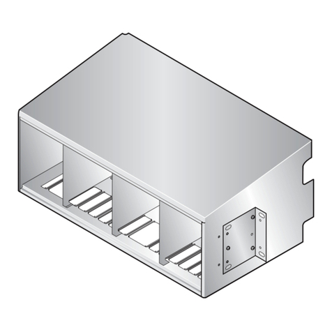
The FCS-717 List 2B COT shelf (see Figure 1) supports:
•one alarm unit or Pair Gain Test Controller (PGTC) Interface unit common to all systems
•up to three PG-Flex subscriber carrier systems where each system consists of one line unit and one to three
channel units (for a shelf maximum of three line units and 9 channel units)
Additionally, the shelf provides termination points for alarms, power, metallic bypass pairs, auxiliary power pairs
when using a doubler, and subscriber circuits (located on the backplane, see Figure 2 on page 8). The
FCS-717 List 2B COT shelf provides wire-wrap terminations (P1, P2, and P3) for the subscriber circuits.
Figure 1. FCS-717 List 2B COT Shelf (Card-side, Front View)
Features of the PG-Flex FCS-717 List 2B COT shelf are:
•universal mounting brackets for installation into a 19- or 23-inch equipment bay
•wire-wrap connections for High-bit-rate Digital Subscriber Line (HDSL), alarms, metallic bypass pairs, and
auxiliary power pairs (when using a doubler)
•split or single battery feed for shelf powering
•screw terminal connections for frame ground and Central Office (CO) battery
•DB-25 connector for Network Management Access (NMA) communications
•wire-wrap terminations for subscriber circuit connections
Use the FCS-717 List 2B COT 19-inch shelf only with a List 4x (or higher) FRE-765 Remote
Terminal (RT) enclosure.
Alarm Unit or
PGTC Interface Unit System 1
CUs 1-3LU1 LU2 LU3CUs 1-3 CUs 1-3
System 2 System 3

Functional Description SCP-FCS717-022-03H
2 January 6, 2003 FCS-717 List 2B
•25-pair Amphenol connector for PGTC test interface
Specifications
Electrical Characteristics
Power -48 Vdc CO battery
Composite Clock Termination 133 Ω
Environmental
Operating Temperature -40° F to +150° F (-40° C to +65° C)
Operating Humidity 5% to 95% (non-condensing)
Operating Elevation -200 feet to 13,000 feet (-60 m to 4000 m)
Physical
Mounting 19- or 23-inch equipment bay using universal mounting brackets
Dimensions
Height 19.00 in. (48.3 cm.)
Width 8.75 in. (22.2 cm.)
Depth 11.75 in. (29.8 cm.)
Weight 15.25 lb. (6.9 kg.)
FUNCTIONAL DESCRIPTION
This section describes the FCS-717 List 2B COT shelf operational capabilities and lists the connector pinouts on
the backplane.
Operational Capabilities
Each system (one line unit and one to three channel units) can support up to 24 subscriber channels. Each channel
unit can provide four (4) or eight (8) channels, depending on the service offered. Services offered are:
•Plain Old Telephone Service (POTS)
•Integrated Services Digital Network (ISDN)
Table 1 and Table 2 on page 3 show how the FCS-717 List 2B utilizes channels, dependent on the channel unit
(four or eight channels) and the type of subscriber service (POTS, ISDN, or DDS) selected.
A label on the FCS-717 List 2B COT shelf indicates numbering for the line and channel units.
When the line units are a List 1 or 2, black numbers indicate sequential channel unit
numbering 1 through 9. When the line units are List 3 or higher, blue numbers indicate
channel unit numbering 1 through 3 for each of the four systems.

SCP-FCS717-022-03H Functional Description
FCS-717 List 2B January 6, 2003 3
Table 1. Channel Unit Circuit Utilization
Channel unit Service Configurations
Channel Unit 8-Channel POTS 4-Channel ISDN 4-Channel DDS*
T/R 1 Ckt 1 Ckt 1 Ckt 1 Tx
T/R 2 Ckt 2 Ckt 2 Ckt 1 Rcv
T/R 3 Ckt 3 Ckt 3 Ckt 2 Tx
T/R 4 Ckt 4 Ckt 4 Ckt 2 Rcv
T/R 5 Ckt 5 —Ckt 3 Tx
T/R 6 Ckt 6 —Ckt 3 Rcv
T/R 7 Ckt 7 —Ckt 4 Tx
T/R 8 Ckt 8 —Ckt 4 Rcv
* DDS is not currently supported.
Table 2. Channel Unit Circuit Utilization*
(*) The Channel Unit (CU) numbers on top (CU 1 through CU 9) show how the channel units are
numbered when using a List 1 or List 2 line unit. The CU numbers in parentheses (CU 1
through CU 3) show how the channel units are numbered when using a List 3 or higher line
unit, relative to each system.
System 1 System 2 System 3
CU 1
(CU 1)
CU 2
(CU 2)
CU 3
(CU 3)
CU 4
(CU 1)
CU 5
(CU 2)
CU 6
(CU 3)
CU 7
(CU 1)
CU 8
(CU 2)
CU 9
(CU 3)
ckt 1 ckt 1 ckt 1 ckt 1 ckt 1 ckt 1 ckt 1 ckt 1 ckt 1
ckt 2 ckt 2 ckt 2 ckt 2 ckt 2 ckt 2 ckt 2 ckt 2 ckt 2
ckt 3 ckt 3 ckt 3 ckt 3 ckt 3 ckt 3 ckt 3 ckt 3 ckt 3
ckt 4 ckt 4 ckt 4 ckt 4 ckt 4 ckt 4 ckt 4 ckt 4 ckt 4
ckt 5 ckt 5 ckt 5 ckt 5 ckt 5 ckt 5 ckt 5 ckt 5 ckt 5
ckt 6 ckt 6 ckt 6 ckt 6 ckt 6 ckt 6 ckt 6 ckt 6 ckt 6
ckt 7 ckt 7 ckt 7 ckt 7 ckt 7 ckt 7 ckt 7 ckt 7 ckt 7
ckt 8 ckt 8 ckt 8 ckt 8 ckt 8 ckt 8 ckt 8 ckt 8 ckt 8

Functional Description SCP-FCS717-022-03H
4 January 6, 2003 FCS-717 List 2B
Backplane Connections
Table 4 through Table 6 provides the connector pinouts located on the backplane for alarm or Pair Gain Test
Controller (PGTC) interface unit, line unit, and channel unit connectors.
Table 7 on page 8 provides connectors and termination points located on the backplane for:
•CO power (-48V_A, -48V_B) and CO return (RTN_A, RTN_B)
•frame ground
•Local Area Network (LAN)
•data
•HDSL, test, composite clock, auxiliary power pairs, and external Alarm Cutoff (ACO) switch
•alarm or PGTC test interface
•subscriber lines with .045” wire-wrap terminations (P1, P2, and P3)
Table 3 lists the FCS-717 List 2B connectors and where each is described in this practice (see Figure 2 on page 8
for connector locations).
Table 3. FCS-717 List 2B Card Connectors
Connector and Fuse Go to On
Alarm Unit or PGTC Interface Unit Table 4 page 5
Line Unit Connectors (Systems 1 thru 3) Table 5 page 6
Channel Unit Connectors (Systems 1 thru 3) Table 6 page 7
Use the Information in Table 4 through Table 6 for diagnostic and troubleshooting procedures
under the direction of an authorized ADC technical support representative.

SCP-FCS717-022-03H Functional Description
FCS-717 List 2B January 6, 2003 5
Table 4. Alarm Unit or PGTC Interface Unit Connector
J1-C Pin J1-C Signal J1-B Pin J1-B Signal J1-A Pin J1-A Signal
1LAN 1LGND (CDS) 1NMA_CD
2CRIT_MAJ_NO 2INHIBIT 2CRIT_MAJ_COM
3 PGTC_TIP1 3 SLEEVE1 3TESTIN-T_1
4PGTC_RING1 4SLEEVE2 4TESTIN-R_1
5 PGTC_TIP2 5 SLEEVE3 5TESTIN-T_2
6PGTC_RING2 6SLEEVE4 6TESTIN-R_2
7 PGTC_TIP3 7 OH1 7TESTIN-T_3
8PGTC_RING3 8OH2 8TESTIN-R_3
9 PGTC_TIP4 9 OH3 9TESTOUT-T_1
10 PGTC_RING4 10 OH4 10 TESTOUT-R_1
11 N/C (BURN-IN) 11 PROCEED1 11 TESTOUT-T_2
12 LOCK1 12 PROCEED2 12 TESTOUT-R_2
13 LOCK2 13 PROCEED3 13 TESTOUT-T_3
14 LOCK3 14 PROCEED4 14 TESTOUT-R_3
15 LOCK4 15 SEIZE 15 N/C
16 TMAJ 16 SEZBY 16 N/C
17 +5_2 17 TSTALM 17 +5_1
18 NMA_TX 18 NMA_RX 18 NMA_DTR
19 NMA_DSR 19 NMA_TCLK 19 NMA_RCLK
20 NMA_BUS_1 20 NMA_BUS_2 20 N/C
21 NMA_BUS_3 21 NMA_BUS_4 21 N/C
22 CC1_TIP 22 CC1_RING 22 EXT_ACO
23 CC2_TIP 23 CC2_RING 23 8KHZ_CC
24 SHELF_ID_NO 24 SHELF_ID_COM 24 SHELF_ID_NC
25 MAJ_AUD_NO 25 MAJ_AUD_COM 25 MAJ_AUD_NC
26 MAJ_VIS_NO 26 MAJ_VIS_COM 26 MAJ_VIS_NC
27 MIN_AUD_NO 27 MIN_AUD_COM 27 MIN_AUD_NC
28 MIN_VIS_NO 28 MIN_VIS_COM 28 MIN_VIS_NC
29 FUSEALARM 29 MAJORALARM 29 MINORALARM
30 -48V_B (BATT) 30 N/C 30 -48V_A (BATT)
31 BATT_RTN 31 BATT_RTN 31 BATT_RTN
32 PROTGND 32 GND 32 GND

Functional Description SCP-FCS717-022-03H
6 January 6, 2003 FCS-717 List 2B
Table 5. Line Unit Connectors
System Line Unit Connector
11J2
2 2 J7
3 3 J12
Pin Signal* Pin Signal*
1 PROTGND 2 PROTGND
3 N/C 4 N/C
5 HDSL_TIP1_EX_n 6 HDSL_TIP2_EX_n
7 HDSL_RING1_EX_n 8 HDSL_RING2_EX_n
9 N/C 10 N/C
11 BATT_RTN 12 BATT_RTN
13 -48_n 14 -48_n
15 BATT_x-† 16 BATT_x-†
17 8KHZ_CC 18 N/C (BURN-IN)
19 TSYNC_n 20 TSIG_n
21 TCLK_n 22 TSER_n
23 GND 24 RSYNC_n
25 RSIG_n 26 RCLK_n
27 RSER_n 28 GND
29 SDA_n 30 CSYNC_n
31 FUSEALARM 32 SCL_n
33 +5_n 34 +5_n
35 GND 36 GND
37 -5_n 38 -5_n
39 NMA_BUS_n 40 CID3
41 CID2 42 CID1
43 MAJORALARM 44 MINORALARM
45 TESTIN-T_n 46 TESTIN-R_n
47 TESTOUT-T_n 48 TESTOUT-R_n
49 N/C 50 N/C
51 BYPASS-T_n 52 BYPASS-R_n
53 HDSLTIP1_n 54 HDSLTIP2_n
55 HDSLRING1_n 56 HDSLRING2_n
57 N/C 58 N/C
59 PROTGND 60 PROTGND
* Where n is 1, 2, or 3 for Systems 1, 2, or 3 respectively.
† Where x is A for Systems 1 and 2 and B for System 3.

SCP-FCS717-022-03H Functional Description
FCS-717 List 2B January 6, 2003 7
Table 6. Channel Unit Connectors Pinouts for Systems 1, 2, and 3
System Channel Unit Connector
11J3
2 1 (4)* J8
3 1 (7)* J13
System Channel Unit Connector
12J4
2 2 (5)* J9
3 2 (8)* J14
System Channel Unit Connector
13J5
2 3 (6)* J10
3 3 (9)* J15
Pin Signal Pin Signal Pin Signal Pin Signal Pin Signal Pin Signal
1PROTGND 2PROTGND 1PROTGND 2PROTGND 1PROTGND 2PROTGND
3TIP05_n4RING05_n3TIP13_n4RING13_n3TIP21_n4RING21_n
5TIP06_n6RING06_n5TIP14_n6RING14_n5TIP22_n6RING22_n
7TIP07_n8RING07_n7TIP15_n8RING15_n7TIP23_n8RING23_n
9TIP08_n10 RING08_n9TIP16_n10 RING16_n9TIP24_n10 RING24_n
11 BATT_RTN 12 BATT_RTN 11 BATT_RTN 12 BATT_RTN 11 BATT_RTN 12 BATT_RTN
13 -48_n14 -48_n13 -48_n14 -48_n13 -48_n14 -48_n
15 -48V_x‡
(BATT)
16 -48V_x‡
(BATT)
15 -48V_x‡
(BATT)
16 -48V_x‡
(BATT)
15 -48V_x‡
(BATT)
16 -48V_x‡
(BATT)
17 8KHZ_CC 18 N/C
(BURN-IN)
17 8KHZ_CC 18 N/C
(BURN-IN)
17 8KHZ_CC 18 N/C
(BURN-IN)
19 TSYNC_n20 TSIG_n19 TSYNC_n20 TSIG_n19 TSYNC_n20 TSIG_n
21 TCLK_n22 TSER_n21 TCLK_n22 TSER_n21 TCLK_n22 TSER_n
23 GND 24 RSYNC_n23 GND 24 RSYNC_n23 GND 24 RSYNC_n
25 RSIG_n26 RCLK_n25 RSIG_n26 RCLK_n25 RSIG_n26 RCLK_n
27 RSER_n28 GND 27 RSER_n28 GND 27 RSER_n28 GND
29 SDA_n30 CSYNC_n29 SDA_n30 CSYNC_n29 SDA_n30 CSYNC_n
31 N/C 32 SCL_n31 N/C 32 SCL_n31 N/C 32 SCL_n
33 +5_n34 +5_n33 +5_n34 +5_n33 +5_n34 +5_n
35 GND 36 GND 35 GND 36 GND 35 GND 36 GND
37 -5_n38 -5_n37 -5_n38 -5_n37 -5_n38 -5_n
39 N/C 40 CID3 39 N/C 40 CID3 39 N/C 40 CID3
41 CID2 42 CID1 41 CID2 42 CID0 41 CID2 42 CID1
43 CID0 44 N/C 43 CID0 44 N/C 43 CID0 44 N/C
45 TESTIN-T_n46 TESTIN-R_n45 TESTIN-T_n46 TESTIN-R_n45 TESTIN-T_n46 TESTIN-R_n
47 GND 48 GND 47 GND 48 GND 47 GND 48 GND
49 TESTOUT-T_
n
50 TESTOUT-R_
n
49 TESTOUT-T_
n
50 TESTOUT-R_
n
49 TESTOUT-T_
n
50 TESTOUT-R_
n
51 TIP01_n52 RING01_n51 TIP09_n52 RING09_n51 TIP17_n52 RING17_n
53 TIP02_n54 RING02_n53 TIP10_n54 RING10_n53 TIP18_n54 RING18_n
55 TIP03_n56 RING03_n55 TIP11_n56 RING11_n55 TIP19_n56 RING19_n
57 TIP04_n58 RING04_n57 TIP12_n58 RING12_n57 TIP20_n58 RING20_n
* The Channel Unit numbers (CU 1 through CU 3) show how the channel units are numbered when using a List 3 or higher line unit, relative
to each system. The Channel Unit numbers in parenthesis (CU 1 through CU 9) show how the channel units are numbered when using a List
1 or List 2 line unit.
†Wherenis 1 for system 1, 2 for system 2, and 3 for system 3.
‡Wherexis A for system 1 and 2, and B for system 3.

Functional Description SCP-FCS717-022-03H
8 January 6, 2003 FCS-717 List 2B
Table 7 lists the FCS-717 List 2B COT shelf backplane connectors and where each is described in this practice.
(Refer to Figure 2 for connector locations and refer to Figure 9 on page 19 for alarm terminations).
Figure 2. FCS-717 List 2B COT Shelf Backplane
59 PROTGND 60 PROTGND 59 PROTGND 60 PROTGND 59 PROTGND 60 PROTGND
Table 7. FCS-717 List 2B COT Shelf Backplane Connectors
Connector and Fuse Go to On
CO Battery, TB1 (-48V_A) and TB2 (-48V_B) Table 8 page 9
CO Battery return, TB3 (RTN_B) and TB4 (RTN_A) Table 8 page 9
Frame Ground (G1) Table 8 page 9
LAN (J6) Table 9 page 9
Data (J21) Table 10 page 9
HDSL, Auxiliary Power Pairs, Composite Clock, Bypass Pair, Frame Ground,
External ACO (not shown in Figure 2)
Table 12 page 16
Alarm Terminations Table 13 page 20
Subscriber Wire-wrap Terminations (P1, P2, and P3) Table 14 page 21
PGTC (P26) Table 15 page 23
Table 6. Channel Unit Connectors Pinouts for Systems 1, 2, and 3
* The Channel Unit numbers (CU 1 through CU 3) show how the channel units are numbered when using a List 3 or higher line unit, relative
to each system. The Channel Unit numbers in parenthesis (CU 1 through CU 9) show how the channel units are numbered when using a List
1 or List 2 line unit.
†Wherenis 1 for system 1, 2 for system 2, and 3 for system 3.
‡Wherexis A for system 1 and 2, and B for system 3.
Subscriber terminations
system 3 (P3)
Subscriber terminations
system 2 (P2) Data connector
(J21)
Subscriber terminations
system 1 (P1) PGTC test interface
(P26)
Frame Ground
(G1)
LAN
connector
(J6)
RTN_A
(TB4) RTN_B
(TB3) -48V_A
(TB1) -48V_B
(TB2)

SCP-FCS717-022-03H Functional Description
FCS-717 List 2B January 6, 2003 9
Table 8. Battery, CO Battery Return, and Frame Ground
Connector Type Function
TB1 Screw Battery (-48V_A) for systems 1 and 2
TB2 Screw Battery (-48V_B) for system 3
TB3 Screw CO battery return B (RTN _B)
TB4 Screw CO battery return A (RTN_A)
G1 Screw Frame Ground (Protection Ground)
Table 9. LAN Connector
Connector Type Function
J6 BNC (Not currently used)
Table 10. DTE Connector (J21) Pinouts
DB-25 (F) Pins Signal
1Frame Ground (GND)
2Transmit Data
3Receive Data
6Data Set Ready
7Signal Common (GND)
8Carrier Detect
15 Transmit Clock
17 Receive Clock
20 Data Terminal Ready

Installation and Test SCP-FCS717-022-03H
10 January 6, 2003 FCS-717 List 2B
INSTALLATION AND TEST
This section provides procedures for unpacking, HDSL pre-provisioning, mounting, and wiring for the
FCS-717 List 2B COT shelf.
Unpacking
Upon receipt of the equipment:
1Unpack each container and visually inspect it for signs of damage. If the equipment has been damaged in
transit, immediately report the extent of damage to the transportation company and to ADC. Order
replacement equipment if necessary.
2Check the contents against the packing list to ensure complete and accurate shipment. If the shipment is short
or irregular, contact ADC as described in “Acronyms” on page 29. If you must store the equipment for a
prolonged period, store the equipment in its original container.
Selecting HDSL Lines
HDSL transmission uses two copper pairs connected between the FCS-717 List 2B COT shelf and RT enclosure.
The wire pairs should have identical electrical make-ups. Differences in total wire length, wire gauge, bridge taps,
and exposure to crosstalk should be kept to a minimum. Pair isolation, (Tip-Ring, Tip-Ground, and Ring-Ground)
must be ≥100k Ω.
The wire pairs from the FCS-717 List 2B COT shelf to the RT enclosure must meet the following guidelines:
•nonloaded cable only
•multigauge is restricted to two gauge changes, except for stubbing or fusing
•total bridge taps may not exceed 2.5 kft. No single bridge tap may exceed 2.0 kft
The distance limitation for HDSL transmission is based on a maximum signal attenuation of 35 dB. Since signal
attenuation decreases as cable size increases, the larger the gauge (19 AWG vs. 26 AWG), the greater the distance
between the FCS-717 List 2B COT shelf and the RT enclosure. Table 11 identifies these distances (at a cable
temperature of 68°F).
Table 11. 24 Channel HDSL Transmission Distances
Gauge Loop Length Resistance
19 AWG
0.9 mm
22.8 kft
7.0 km
367 Ω
22 AWG
0.6 mm
16.1 kft
4.9 km
521 Ω
24 AWG
0.5 mm
12.3 kft
3.7 km
638 Ω
26 AWG
0.4 mm
9.0 kft
2.7 km
750 Ω
Table of contents
Other ADC Indoor Furnishing manuals