ADC DSXpert 2005R User manual

ADCP-80-421
Issue 1
October 2001
1173791 Rev A
DSXpert™ 2005R
DS3/E3 Remote Test Access System
Installation Instructions

ADCP-80-421
Issue 1
October 2001
1173791 Rev A
DSXpert™2005R
DS3/E3 Remote Test Access System
Installation Instructions

ADCP-80-421 • Issue 1 • October 2001 • Preface
Page ii
COPYRIGHT
© 2001, ADC Telecommunications, Inc.
All Rights Reserved
Printed in the U.S.A.
REVISION HISTORY
LIST OF CHANGES
The technical changes incorporated into this issue are listed below.
TRADEMARK INFORMATION
ADC is a registered trademark of ADC Telecommunications, Inc., DSXpert is a trademark of ADC Telecommunications, Inc.
DISCLAIMER OF LIABILITY
Contents herein are current as of the date of publication. ADC reserves the right to change the contents without prior notice. In no
event shall ADC be liable for any damages resulting from loss of data, loss of use, or loss of profits and ADC further
disclaims any and all liability for indirect, incidental, special, consequential or other similar damages. This disclaimer of
liability applies to all products, publications and services during and after the warranty period.
This publication may be verified at any time by contacting ADC’s Technical Assistance Center at 1-800-366-3891, extension 73475
(in U.S.A. or Canada) or 952-917-3475 (outside U.S.A. and Canada), or by e-mail to [email protected]m.
ISSUE DATE REASON FOR CHANGE
1 10/2001 Original publication
PAGE IDENTIFIER DESCRIPTION OF CHANGE
All New publication
ADC Telecommunications, Inc.
P.O. Box 1101, Minneapolis, Minnesota 55440-1101
In U.S.A. and Canada: 1-800-366-3891
Outside U.S.A. and Canada: (952) 938-8080
Fax: (952) 917-1717

Page iii
© 2001, ADC Telecommunications, Inc.
ADCP-80-421 •Issue 1 •October 2001 •Preface
TABLE OF CONTENTS
Content Page
1 GENERAL . . . . . . . . . . . . . . . . . . . . . . . . . . . . . . . . . . . . . . . . . . . . . . . . . . . . . . . . . . . . . . . . . . . . . . . . . . . . . 1
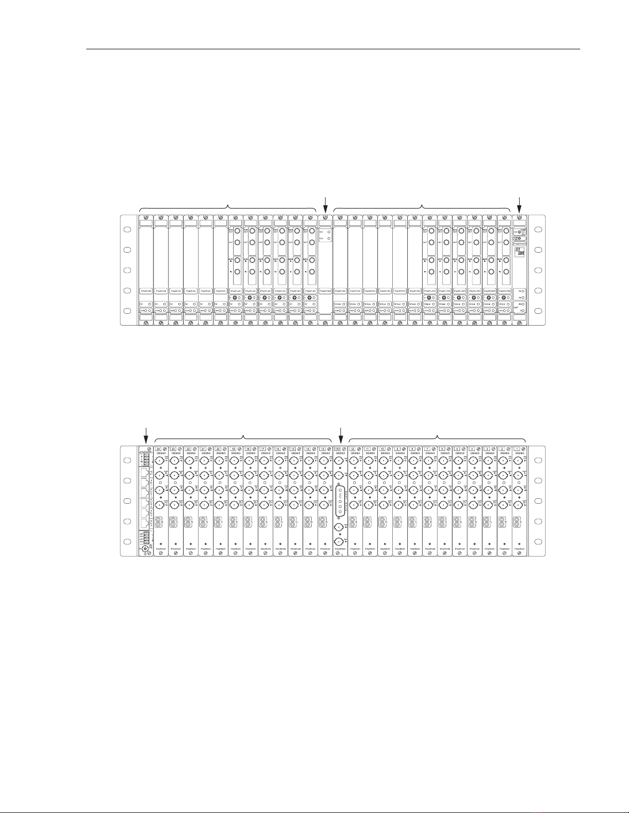
1.1 Chassis Diagrams . . . . . . . . . . . . . . . . . . . . . . . . . . . . . . . . . . . . . . . . . . . . . . . . . . . . . . . . . . . . . . . . . 1
1.2 Description. . . . . . . . . . . . . . . . . . . . . . . . . . . . . . . . . . . . . . . . . . . . . . . . . . . . . . . . . . . . . . . . . . . . . . 1
2 INSTALLATION . . . . . . . . . . . . . . . . . . . . . . . . . . . . . . . . . . . . . . . . . . . . . . . . . . . . . . . . . . . . . . . . . . . . . . . . . 2
2.1 Chassis . . . . . . . . . . . . . . . . . . . . . . . . . . . . . . . . . . . . . . . . . . . . . . . . . . . . . . . . . . . . . . . . . . . . . . . . 2
2.1.1 Communication and Power Supply Card . . . . . . . . . . . . . . . . . . . . . . . . . . . . . . . . . . . . . . . . . . . 4
2.1.2 –48 VDC Power Connection Preparations . . . . . . . . . . . . . . . . . . . . . . . . . . . . . . . . . . . . . . . . . . 4
2.1.3 Connect Office Ground . . . . . . . . . . . . . . . . . . . . . . . . . . . . . . . . . . . . . . . . . . . . . . . . . . . . . . . 6
2.1.4 Alarm Contacts (Optional) . . . . . . . . . . . . . . . . . . . . . . . . . . . . . . . . . . . . . . . . . . . . . . . . . . . . 7
2.1.5 Blank Panels . . . . . . . . . . . . . . . . . . . . . . . . . . . . . . . . . . . . . . . . . . . . . . . . . . . . . . . . . . . . . 8
2.2 Card/Module Installation . . . . . . . . . . . . . . . . . . . . . . . . . . . . . . . . . . . . . . . . . . . . . . . . . . . . . . . . . . . . 9
2.2.1 CPU Card . . . . . . . . . . . . . . . . . . . . . . . . . . . . . . . . . . . . . . . . . . . . . . . . . . . . . . . . . . . . . . . 10
2.2.2 Test Equipment Cards . . . . . . . . . . . . . . . . . . . . . . . . . . . . . . . . . . . . . . . . . . . . . . . . . . . . . . 12
2.2.3 Line Access Cards . . . . . . . . . . . . . . . . . . . . . . . . . . . . . . . . . . . . . . . . . . . . . . . . . . . . . . . . . 13
2.3 Cable Routing . . . . . . . . . . . . . . . . . . . . . . . . . . . . . . . . . . . . . . . . . . . . . . . . . . . . . . . . . . . . . . . . . . . 15
2.3.1 DS3/E3 Line Ports . . . . . . . . . . . . . . . . . . . . . . . . . . . . . . . . . . . . . . . . . . . . . . . . . . . . . . . . . 15
2.3.2 DS3/E3 Test Ports . . . . . . . . . . . . . . . . . . . . . . . . . . . . . . . . . . . . . . . . . . . . . . . . . . . . . . . . . 17
2.3.3 Daisy-Chaining Test Ports (Optional) . . . . . . . . . . . . . . . . . . . . . . . . . . . . . . . . . . . . . . . . . . . . 17
2.3.4 COMM Ports . . . . . . . . . . . . . . . . . . . . . . . . . . . . . . . . . . . . . . . . . . . . . . . . . . . . . . . . . . . . . 18
2.3.5 Daisy-Chaining Chassis (Optional). . . . . . . . . . . . . . . . . . . . . . . . . . . . . . . . . . . . . . . . . . . . . . 21
2.3.6 AUX Ports. . . . . . . . . . . . . . . . . . . . . . . . . . . . . . . . . . . . . . . . . . . . . . . . . . . . . . . . . . . . . . . 22
3 SYSTEM VERIFICATION . . . . . . . . . . . . . . . . . . . . . . . . . . . . . . . . . . . . . . . . . . . . . . . . . . . . . . . . . . . . . . . . . . 22
3.1 LED Test . . . . . . . . . . . . . . . . . . . . . . . . . . . . . . . . . . . . . . . . . . . . . . . . . . . . . . . . . . . . . . . . . . . . . . . 22
4 SPECIFICATIONS. . . . . . . . . . . . . . . . . . . . . . . . . . . . . . . . . . . . . . . . . . . . . . . . . . . . . . . . . . . . . . . . . . . . . . . 24
5 ACTIVITY LEDS . . . . . . . . . . . . . . . . . . . . . . . . . . . . . . . . . . . . . . . . . . . . . . . . . . . . . . . . . . . . . . . . . . . . . . . . 24
6 CUSTOMER INFORMATION AND ASSISTANCE . . . . . . . . . . . . . . . . . . . . . . . . . . . . . . . . . . . . . . . . . . . . . . . . . . . 25


ADCP-80-421 •Issue 1 •October 2001 •Preface
Page v
© 2001, ADC Telecommunications, Inc.
ABOUT THIS MANUAL
This manual provides procedures for installing the DSXpert 2005R, DS3/E3 Remote Test
Access System modular chassis and corresponding chassis components. The manual is intended
for use at communications network facilities and users who monitor and maintain the network.
RELATED PUBLICATIONS
Listed below are related manuals and their publication numbers. Copies of these publications can
be ordered by contacting the ADC Technical Assistance Center at 1-800-366-3891 (in U.S.A. or
Canada) or 952-917-3000, extension 73475 (outside U.S.A. and Canada).
DSXpert 2005R, DS3/E3 Remote Test Access System User Manual ADCP-80-422
ADMONISHMENTS
Important safety admonishments are used throughout this manual to warn of possible hazards to
persons or equipment. An admonishment identifies a possible hazard and then explains what
may happen if the hazard is not avoided. The admonishments —in the form of Dangers,
Warnings, and Cautions —must be followed at all times. These warnings are flagged by use of
the triangular alert icon (seen below), and are listed in descending order of severity of injury or
damage and likelihood of occurrence.
GENERAL SAFETY PRECAUTIONS
Title/Description ADCP Number
Danger: Danger is used to indicate the presence of a hazard that will cause severe personal
injury, death, or substantial property damage if the hazard is not avoided.
Warning: Warning is used to indicate the presence of a hazard that can cause severe personal
injury, death, or substantial property damage if the hazard is not avoided.
Caution: Caution is used to indicate the presence of a hazard that will or can cause minor
personal injury or property damage if the hazard is not avoided.
Danger: To prevent electrical shock, never install equipment in a wet location or during a
lightning storm.
Warning: The chassis must be properly grounded to ensure equipment and human safety.

ADCP-80-421 •Issue 1 •October 2001 •Preface
Page vi
© 2001, ADC Telecommunications, Inc.
COMPLIANCE STATEMENT
This product has been tested and certified to comply with the following requirements:
UL 1950 3rd Edition
FCC Pt-15 Class-A
NEBS Level-3 (GR-1089 CORE and GR-63 CORE)
CSA 22.2 No.950-95
CSA C108.8-M1983 (R1989) (R1994)
EN 60 950 (1992)
EN 300 386-2 V1.1.3
IEC 950
CISPR-22 Class-A (IEC 1000-4-2, IEC 1000-4-3, IEC 1000-4-4, IEC 1000-4-5 and IEC 1000-4-6)
Caution: Electronic modules can be damaged by electrostatic discharge (ESD). Before
handling modules, wear an anti-static discharge wrist strap to prevent damage to electronic
components. Place modules in anti-static packing material when transporting or storing. When
working on modules, always place them on an approved anti-static mat that is electrically
grounded.
Warning: This equipment generates, uses, and can radiate radio frequency energy and if not
installed and used in accordance with the instruction manual, may cause interference to radio
communications. It has been tested and found to comply with limits for a Class A digital device
pursuant to Subpart A of Part 15 of FCC Rules, which are designed to provide reasonable
protection against such interference when operated in a commercial environment. Operation of
this equipment in a residential area is likely to cause interference to TV and radio reception in
which case the user, at their own expense, will be required to take whatever measures may be
required to correct the interference.
This equipment does not exceed Class A limits for radio emission for digital apparatus, set out
in the radio interference regulation of the authorization methods of Industry Canada. Operation
in a residential area may cause unacceptable interference to TV and radio reception requiring
the owner or operator to take whatever steps are necessary to correct the interference.

ADCP-80-421 •Issue 1 •October 2001 •Preface
Page vii
© 2001, ADC Telecommunications, Inc.
LIST OF ACRONYMS AND ABBREVIATIONS
The acronyms and abbreviations used in this manual are detailed in the following list:
10bT 10 Base T
ASCII American Standard Code for Information Interchange
AUX Auxiliary
AWG American Wire Gauge
COMM Communication
CTS Clear to Send
DCE Data Communications Equipment
DIP Dual In-line Package
DS3 Digital Signal, Level 3
DSR Data Set Ready
DTE Data Terminal Equipment
DTR Data Terminal Ready
ESD Electrostatic Discharge
FB Fallback
FCC Federal Communications Commission
GND Ground
RTS Request to Send
RXD Receive Data
TL1 Transaction Language 1
TXD Transmit Data


ADCP-80-421 •Issue 1 •October 2001
Page 1
© 2001, ADC Telecommunications, Inc.
1 GENERAL
1.1 Chassis Diagrams
A front view of the chassis is shown in Figure 1. A rear view of the chassis is shown in Figure 2.
Figure 1. DSXpert 2005R Modular Chassis with Modules Inserted (modules may vary), Front View
Figure 2. DSXpert 2005R Modular Chassis with Modules Inserted (modules may vary), Rear View
1.2 Description
The DSXpert 2005R DS3/E3 Remote Test Access System provides access for testing and
monitoring of unbalanced 75 ohm digital transmission lines, operating at DS3 (44.736 Mbps)
and E3 (34.368 Mbps) transmission rates.
16852-A
FRONT LINE CARDS
SLOTS 1 - 12
FRONT LINE CARDS
SLOTS 13 - 24
TEST CARD
CPU CARD
SLOT
16853-A
REAR LINE CARDS
SLOTS 24 - 13
REAR LINE CARDS
SLOTS 12 - 1
TEST CARD
SLOT
COMM AND
POWER CARD
SLOT

ADCP-80-421 •Issue 1 •October 2001
Page 2
The DSXpert 2005R product family consists of a chassis, up to 24 Front Line Cards, one Front
Test Card, up to 24 Rear Line Cards, one Rear Test Card, one CPU Card, and one
Communication and Power Supply Card. The cards are interconnected via a mid-plane (Mother
Board), which is part of the chassis.
The CPU card is a microprocessor-based card that contains the system firmware and provides
control for the entire chassis. It coordinates all unit functions and communicates with other
units, control consoles and other management devices. The front and rear pair of test equipment
cards coordinate functions for test devices connected to the chassis. The test cards provide BNC
ports to support one test device. The line access cards coordinate functions for the DS3/E3 lines.
There is a pair of one front and rear card for each DS3/E3 circuit; each rear card provides BNC
ports to support one DS3/E3 circuit. The communication and power supply card provides
redundant power at –48 V DC to the chassis and modules. The communication and power
supply card is located in left slot on the rear of the chassis.
The DSXpert equipment is normally shipped with the modules installed in the chassis. If the
modules are not contained in the chassis location slots when the equipment is received, perform
the necessary module installation procedures.
2 INSTALLATION
It is recommended that the DSXpert 2005R installation procedures be followed in the order that
they are presented in the manual, as listed in the Table of Contents.
Some chassis may be fully configured prior to shipment and can therefore be installed directly
into a rack when received. Otherwise, the chassis should be configured according to the
installation sections of the manual.
2.1 Chassis
The DSXpert 2005R chassis is designed for 23 inch WECO or EIA mounting. The chassis is
5.97 inch high by 23 inch wide by 11.97 inch deep and can be mounted flush, 2 or 6 inch recess.
Install the chassis into rack as shown in Figure 3.
Danger: To prevent electrical shock, never install equipment in a wet location or during a
lightning storm.
Caution: Electronic modules can be damaged by electrostatic discharge (ESD). Before
handling modules, wear an anti-static discharge wrist strap to prevent damage to electronic
components. Place modules in anti-static packing material when transporting or storing. When
working on modules, always place them on an approved anti-static mat that is electrically
grounded.

ADCP-80-421 •Issue 1 •October 2001
Page 3
© 2001, ADC Telecommunications, Inc.
Figure 3. Chassis Installation into the Rack
This procedure provides instructions for installing the chassis in an EIA or WECO 23-inch
equipment rack. The mounting brackets are adjustable to permit the chassis to be mounted
flush, 2, or 6 inch recess. Check the work order to determine the chassis location in the rack.
1. Obtain the following tools and equipment:
•Flat blade or Phillips screwdriver (type to match mounting screws)
•#12-24 - 0.5-inch binder head machine screws. (Four required.)
2. Check the work order to determine if the chassis should be installed with a flush, 2-inch,
or 6-inch recess. If a 2-inch recess is specified, proceed to Step 5. If a 6-inch recess is
specified, remove the screws that secure the mounting brackets to the sides of the chassis
and remove each bracket from the chassis.
3. Align each bracket with the appropriate set of bracket mounting holes on the side of the
chassis.
4. Secure the mounting brackets to the sides of the chassis using the screws removed in
Step 2
.
5. Locate the equipment rack mounting space that is specified for the chassis.
6. Place the chassis in the assigned mounting space and align the holes in the mounting
brackets with the holes in the equipment rack.
7. Secure the mounting brackets to the equipment rack using the 12-24 - 0.5-inch binder head
machine screws provided.
8. Tighten the four mounting screws securely.
16854-A

ADCP-80-421 •Issue 1 •October 2001
Page 4
© 2001, ADC Telecommunications, Inc.
2.1.1 Communication and Power Supply Card
The Communication and Power Supply Card shown in Figure 4 provides the physical
connections for all communication interfaces and –48Vdc power.
Figure 4. Installing Communication and Power Supply Card
If necessary remove blank panel see Section 2.1.5.
Secure module in the chassis by tightening the screws at the top and bottom of the module.
2.1.2 –48 VDC Power Connection Preparations
This procedure describes how to connect the –48 Vdc “1”and “2”office battery to the chassis.
Two –48 Vdc power sources (1 and 2) are required to provide redundant power to the chassis.
There is a pair of male-to-female Input Power connectors (–48 Vdc, 2.5 A max) located on the
Communication and Power Supply card. This card is installed on the rear of the chassis.
Figure 5 shows a pair of male and female connectors.
Caution: Electronic modules can be damaged by electrostatic discharge (ESD). Before
handling modules, wear an anti-static discharge wrist strap to prevent damage to electronic
components. Place modules in anti-static packing material when transporting or storing. When
working on modules, always place them on an approved anti-static mat that is electrically
grounded.
16861-A

ADCP-80-421 •Issue 1 •October 2001
Page 5
© 2001, ADC Telecommunications, Inc.
Figure 5. –48Vdc Input Power Connector, Male-to-Female
1. Obtain the items listed below:
•Flat Blade screw driver
•Wire, 18-22 awg (color code per local practice). Recommended wire size for the power
leads, when fused in the same bay.
2. Route a pair of power supply wires from two separate power sources to the power supply
card slot at the rear of the chassis. Separately fuse each –48 Vdc power source but do not
install fuses at this time.
3. Connect the wires to the designated terminals on the fuse panel.
4. Dress and secure the wires to the rack following local practice.
5. Route the wires to the power supply card slot at the rear of the chassis and cut them to
length, allowing sufficient length for termination.
6. Label the ends of the two power supply wiring pairs with the following designations:
•Pair 1: –48A, RTN 1
•Pair 2: –48B, RTN 2
7. For wire connection, insert wire into wire slots on the male connector as shown in
Figure 6. Wire should be stripped to approximately 3/16-inch. Secure wire by tightening
the top small screws on the male connector.
8. Update office records as required.
Warning: Before making any connections to the chassis, verify that the power is off (fuse
removed at the fuse and alarm panel) and that all plug-in modules are removed from the
chassis. Do not install plug-in modules until after the chassis wiring is completed.
Warning: To fully power down the unit equipped with –48Vdc connectors, shut off power at the
connecting power source. Do not disconnect dc connectors at terminal blocks on rear of chassis
while power is being supplied to the unit.
16870-A

ADCP-80-421 •Issue 1 •October 2001
Page 6
© 2001, ADC Telecommunications, Inc.
Figure 6. –48Vdc Input Power Connector, Wiring
2.1.3 Connect Office Ground
This procedure establishes a ground connection between the chassis and the office ground
connection. A frame ground termination screw is provided on the chassis, for frame ground
connection. This connection must be made in accordance with all local and national electrical
codes.
1. Obtain the following:
•Ground braid
2. Connect one end of the ground braid to the ground stud on the chassis and tighten the nut
securely.
3. Connect the other end of the ground braid to the office ground conductor. Ensure this
connection is made using methods and hardware that meets all applicable local and
national electrical codes.
After installing Power Supply Card connect male connector to female connector on chassis rear
as shown in Figure 7.
Figure 7. –48Vdc Input Power Connector, Male-to-Female Connection
RTN
-48V
~3/16 IN.
18-22 AWG
TURN SCREWS
CLOCKWISE TO
SECURE WIRE 16871-A
16872-A

ADCP-80-421 •Issue 1 •October 2001
Page 7
© 2001, ADC Telecommunications, Inc.
Install fuses in fuse and alarm panel for the DSXpert Chassis.
2.1.4 Alarm Contacts (Optional)
There is a pair of male-to-female power alarm connectors located on the Communication and
Power Supply card on the rear of the chassis. These can be connected to an alarm unit
(optional). Alarm contact one indicates a major system failure (loss of power or CPU failure).
Alarm contact two is used to indicate a specific failure associated with self-diagnostic,
performance monitoring, or other user defined alarm conditions. Both contacts are normally
open. Figure 8 shows a pair of male and female connectors.
Figure 8. Alarm Contacts Connectors, Male-to-Female
For wire connection, insert wire (18-22 awg) into wire slots on the male connector as shown in
Figure 9. Wire should be stripped to approximately 3/16-inch. Secure wire by tightening the top
small screws on the male connector.
Figure 9. Alarm Connector, Wiring
Warning: To fully power down the unit equipped with –48Vdc connectors, shut off power at the
connecting power source. Do not disconnect dc connectors at terminal blocks on rear of chassis
while power is being supplied to the unit.
16873-A
2
1
~3/16 IN.
18-22 AWG
TURN SCREWS
CLOCKWISE TO
SECURE WIRE 16874-A

ADCP-80-421 •Issue 1 •October 2001
Page 8
© 2001, ADC Telecommunications, Inc.
Connect the opposite ends of the wires to the input connectors of the alarm unit. Refer to the
installation manual of the alarm unit for wiring connections.
After installing Power Supply Card connect alarm male connector to female connector on
chassis rear as shown in Figure 10.
Figure 10. Alarm Connector, Male-to-Female Connection
2.1.5 Blank Panels
If applicable, remove blank panels by loosening fastener screws and pulling out from chassis as
shown in Figure 11 and Figure 12.
Figure 11. Removing Blank Front Panels
16875-A
16855-A

ADCP-80-421 •Issue 1 •October 2001
Page 9
© 2001, ADC Telecommunications, Inc.
Figure 12. Removing Blank Rear Panels
2.2 Card/Module Installation
The DSXpert 2005R chassis accommodates 24 Front Line Cards (FLC), 24 Rear Line Cards
(RLC), one Front Test Card (FTC), one Rear Test Card (RTC), one CPU Card (front), and one
Communication and Power Supply card (rear).
The line cards are inserted into slots sequentially numbered from 1 to 24. Slots 1-12 and 13-24
are intended for line cards (front and rear). Slot TST is dedicated for the test card (front and
rear). Right most slot is dedicated for the CPU Card (front). Left most slot is dedicated for the
Communication and Power Supply card (rear). All cards plug into a mid-plane (Mother Board),
which is permanently assembled in the chassis.
2.2.1 CPU Card
Before installing the CPU card, the onboard DIP switches must be properly configured to
ensure proper operation of the DSXpert unit.
The DSXpert 2005R unit has one bank of DIP switches, located on the CPU card, as shown in
Figure 13.
Caution: Electronic modules can be damaged by electrostatic discharge (ESD). Before
handling modules, wear an anti-static discharge wrist strap to prevent damage to electronic
components. Place modules in anti-static packing material when transporting or storing. When
working on modules, always place them on an approved anti-static mat that is electrically
grounded.
16856-A

ADCP-80-421 •Issue 1 •October 2001
Page 10
© 2001, ADC Telecommunications, Inc.
Figure 13. CPU Card DIP Switches
CPU DIP switch settings are shown in Table 1.
The CPU card as shown in Figure 14. The CPU card for the DSXpert modular chassis is hot-
swappable and can be inserted and removed without powering down the chassis. Install the
CPU card in the right most slot when viewed from the front. Secure module in the chassis by
tightening the screws at the top and bottom of the module.
Table 1. CPU DIP Switch Positions
DIP SWITCH PACKAGE
1234Function Notes
on COMM IN baud rate=9600 bps
off COMM IN baud rate=19200 bps (Default)
off Not used Set to “off”
off Bypass security=off (Default) When set to ON, the unit clears tel-
net and menu passwords, and sets
TL1 ACT-USER level back to zero.
Disables telnet menu and TL1 pass-
words.
on Bypass security=on
5678Function Notes
off Not used, (Default) Set to “off”
16863-A
ON
OFF

ADCP-80-421 •Issue 1 •October 2001
Page 11
© 2001, ADC Telecommunications, Inc.
Figure 14. Installing CPU Card
The NORM/ALM LED should blink green after the power-up sequence is complete and no
alarm condition is present. The PS1 and PS2 LEDs should be a steady green.
2.2.2 Test Equipment Cards
The slot marked TST located in the middle of the chassis both front and rear is dedicated to the
Test Card.
Refer to work order to determine if Test Cards are being used. Install Test Cards as shown in
Figure 15 and Figure 16.
Secure module in the chassis by tightening the screws at the top and bottom of the module.
The Test Equipment Card has one green LED (labeled TST1). When operting properly the LED
is illuminated green.
16862-A
Table of contents