ADDAC System ADDAC701 User manual


October.2019
ADDAC701 Assembly Guide
ADDAC SYSTEM page 2
Tools Needed:
Oscilloscope
Wire cutter
Pliers
Philips key

ADDAC SYSTEM page 3
STEP 1:
Break the pcbs apart and grab the bottom pcb, also locate the 7805 regulator and the two Capacitors.
Place and solder them like shown below.
ADDAC701 Assembly Guide

79L05 10k
20k
78L10
ADDAC SYSTEM page 4
STEP 3:
Next locate the thru-hole capacitor, two trimmers 10k and 20k (marked 103 and 203) and the two
thru-hole voltage regulators.
Place them and solder them like shown below.
ADDAC701 Assembly Guide

ADDAC SYSTEM
STEP 6:
Locate the male pinheaders, place and solder them like shown below.
page 5
ADDAC701 Assembly Guide

ADDAC SYSTEM page 6
ADDAC701 Assembly Guide
STEP 8:
Locate power connector, place and solder it like shown below, make sure the indent is facing right.

STEP 11:
Next we move on to the top pcb, locate it as well as the female pinheaders, place and solder them like
shown below.
ADDAC SYSTEM page 7
ADDAC701 Assembly Guide

ADDAC SYSTEM page 8
STEP 13:
Grab the top pcb and with the help of a screwdriver rotate it against the bottom hole to slightly open it
creating a V shape. This will allow the plastic screw to sink, as much as possible, into the hole.
Locate and place the two spacers into the back of the top pcb.
Please note that the plastic screw goes on the bottom hole.
ADDAC701 Assembly Guide

50k100k
100k
5k
ADDAC SYSTEM page 9
STEP 13:
Last step, locate, place and solder the remaining trimmers like shown below.
502 = 5k
503 = 50k
104 = 100k
ADDAC701 Assembly Guide
ADDAC SYSTEM page 10
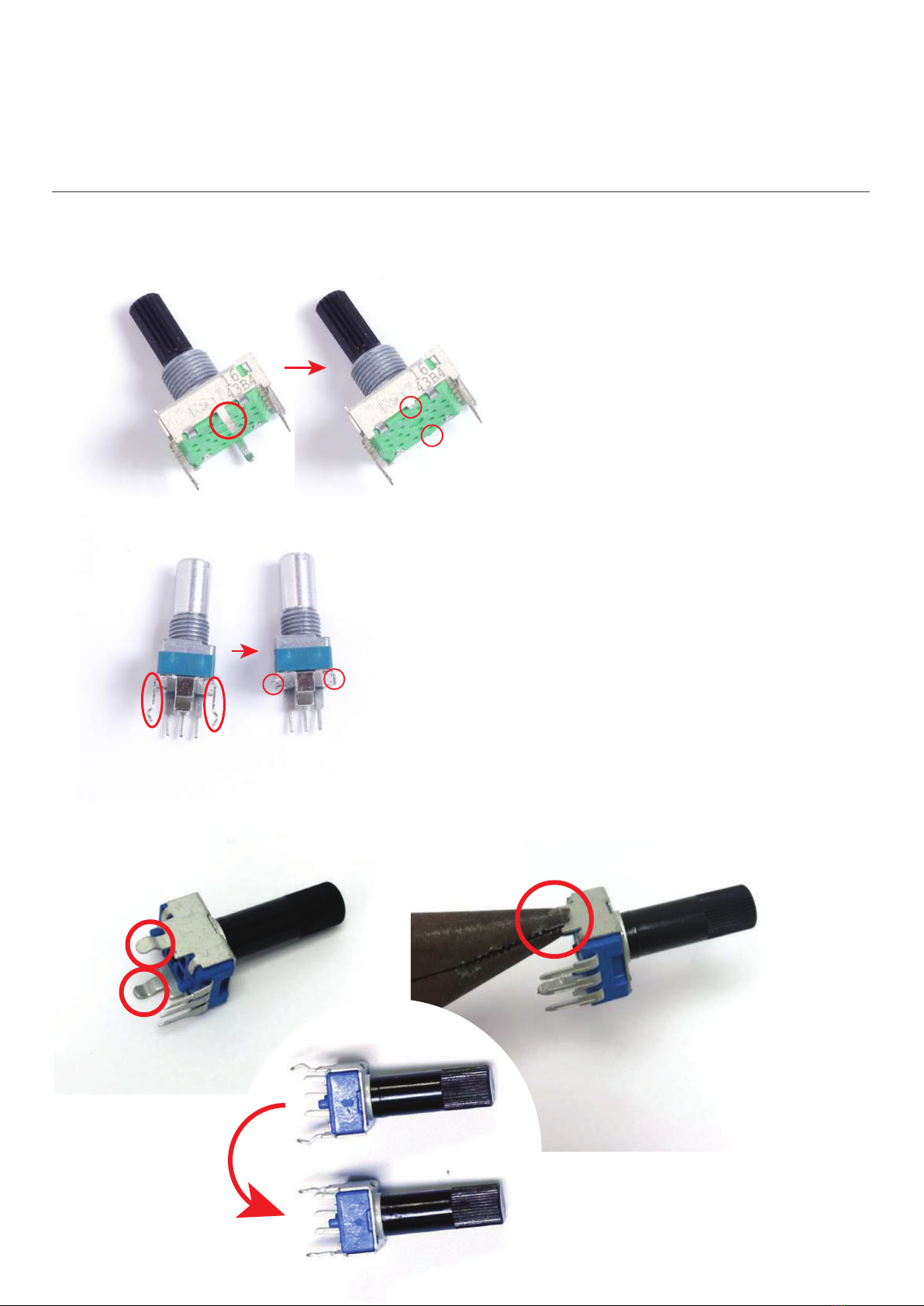
STEP 13:
Next we’ll need to prepare some parts before adding them to the front panel.
Locate the rotary switch and trim the middle legs like shown below.
ADDAC701 Assembly Guide
STEP 7:
Grab the plastic shaft trim pots and flatten out their legs with the help of some pliers, like shown below.
STEP 7:
Locate the two metal shaft pots and trim the middle legs like shown below.

ADDAC SYSTEM page 11
STEP 13:
Now place all parts taking in attention the notes below
ADDAC701 Assembly Guide
Threaded Jacks
Cut this jack piece to fit
on top of plastic screw
Threaded Jacks
Non-threaded
Jacks
Non-threaded
Jacks
cut
3 Position
Switch
Notice
Orientation
“Round” side up!
2 Position
Switch

ADDAC SYSTEM page 12
STEP 13:
Place the panel on top of the parts and tighten the six nuts.
ADDAC701 Assembly Guide

ADDAC SYSTEM page 13
STEP 13:
Adjust the height of the pcb keeping it parallel to the front panel.
Solder all parts.
ADDAC701 Assembly Guide
Keep lines parallel

ADDAC SYSTEM page 14
STEP 13:
Last step, close the 2 pcbs together amd place the two bottom screws.
ADDAC701 Assembly Guide

ADDAC SYSTEM page 15
Finish it by placing the knobs and you’ve finished the
assembly process!
Proceed to the calibration method.
ADDAC701 Assembly Guide

ADDAC SYSTEM page 16
CONSIDERATIONS
For this process you’ll need an Oscilloscope, a tuner ans a
precision voltage source, the precision of both the tuner
and the voltage source may have an impact on the overall
calibration process.
INITIAL SETUP
1. Start by setting the “FREQUENCY” knob at "0"
2. Set the “OCTAVE” rotary switch at "0"
3. Set “FINE TUNE” knob at 12 0’clock
4. Set the "INITIAL FREQUENCY" trimmer to the lowest
frequency possible.
5. Set the “INITIAL FREQUENCY" trimmer to C1 (32.70Hz).
TUNING THE 1V/OCT
With a precision voltage from a keyboard or a quantizer
(such as ADDAC207 in keyboard mode) plug it to the
1v/oct input.
1. Feed 0v, tuner frequency should be C1 (32.70Hz)
2. Feed 3V, tuner frequency should be C4 (261.63Hz)
3. Calibrate the ”SCALE” trimmer to match a perfect C4.
4. Feed 0v, the tuner frequency should be C1, if so skip
next step otherwise follow to the next step.
5. Adjust “FINE TUNE” knob to match a perfect C1 and go
back to Step 2.
Be aware that you may need to go through this loop,
(steps 2 through 5) several times. Each time you’ll notice
less and less drift.
FINE TUNING HIGHER FREQUENCIES
1. Feed 0v, tuner frequency should be a perfect C1.
2. Feed 5V tuner frequency should be a perfect C6, if so
skip next step otherwise follow to the next step.
3. Calibrate the “HIGH FREQUENCY CALIBRATION" trimmer
to match a perfect C6.
TUNING C1
Set the ”FREQUENCY” knob at "0" and “FINE TUNE” knob at
12 o’clock. Feed 0V to the 1v/oct input and set the "INITIAL
FREQUENCY" trimmer to C1 (32.70Hz).
TUNING THE RANGE SWITCH
Unplug any source that is connected to the 1v/oct input
and set it to a perfect C1.
Turn the frequency switch to “+5” and trim the "Range
ADJ" trimmer to C6 (1046.50Hz).
ADDAC701 Calibration Guide
Calibration
INITIAL
FREQUENCY
(INIT.F.)
1v/Oct
(SCALE)
HIGH
FREQUENCY
CALIBRATION
(HIGH F.)
SINE
SYMMETRY
(S.SYM)
SINE
SHAPE
(S.SHAPE)
OCTAVE
SWITCH
(RANGE ADJ.)
BOTTOM PCB
TOP PCB
TRIMMER LOCATIONS

ADDAC SYSTEM page 17
CALIBRATING THE SINE SYMMETRY
1. Connect the “Sine Output” to an oscilloscope
2. The “Sine Symmetry” trimmer acts like an Offset for the
Sine center position adjust it until you have a symetrical
shape between the positive and negative side.
CALIBRATING THE SINE SHAPE
3. The “Sine Shape” trimmer acts like a a linear to log/exp
converter from the triangle waveform, too much and you
get something close to a square wave, too little becomes
closer to the initial triangle. As you tune it closer to the
typical sine waveform you’ll hear the undesired harmonics
disappearing.
While all other instructions in these callibration instruc-
tions have very precise settings, the Sine Shape can be
calibrated to the user’s prefered timbre, so look at the sine
on the oscilloscope make sure it’s close to perfect and
leave it at that sweet spot where your ears tell you to.
ADDAC701 Calibration Guide
Sine Calibration
SINE SHAPE
SINE SYMMETRY
GOOD
OVERSHOT
UNDERSHOT
GOOD
OVERSHOT
UNDERSHOT

For feedback, comments or problems please contact us at:
ADDAC701 ASSEMBLY GUIDE
October.2019Revision.02
Table of contents
Popular Power Tools manuals by other brands

Titan Tool
Titan Tool LX-80 II instruction sheet

Senco
Senco RoofPRO455 operating instructions

Central Machinery
Central Machinery Central Machinery 13" Bench Drill Press owner's manual

Bosch
Bosch GBH 14,4 V-LI Compact Professional Original instructions

Parkside
Parkside PHLG 2000 B1 Operation and safety notes

Constructor
Constructor CHAGD2003-BM Original instructions


