Addi-Data MSX-E1516 Parts list manual

DIN EN ISO 9001:2008 certified Edition: 02.02-03/2015
TECHNICAL
DESCRIPTION
MSX-E1516
Ethernet digital I/O system

Product information
This manual contains the technical installation and important instructions for correct commissioning
and usage, as well as production information according to the current status before printing.
The content of this manual and the technical product data may be changed without prior notice.
ADDI-DATA GmbH reserves the right to make changes to the technical data and the materials included
herein.
Warranty and liability
The user is not permitted to make changes to the product beyond the intended use, or to interfere
with the product in any other way.
ADDI-DATA shall not be liable for obvious printing and phrasing errors. In addition, ADDI DATA, if
legally permissible, shall not be liable for personal injury or damage to materials caused by improper
installation and/or commissioning of the product by the user or improper use, for example, if the
product is operated despite faulty safety and protection devices, or if notes in the operating
instructions regarding transport, storage, installation, commissioning, operation, thresholds, etc. are
not taken into consideration. Liability is further excluded if the operator changes the product or the
source code files without authorisation and/or if the operator is guilty of not monitoring the
permanent operational capability of working parts and this has led to damage.
Copyright
This manual, which is intended for the operator and its staff only, is protected by copyright.
Duplication of the information contained in the operating instructions and of any other product
information, or disclosure of this information for use by third parties, is not permitted, unless this right
has been granted by the product licence issued. Non-compliance with this could lead to civil and
criminal proceedings.
ADDI-DATA software product licence
Please read this licence carefully before using the standard software. The customer is only granted the
right to use this software if he/she agrees with the conditions of this licence.
The software must only be used to set up the ADDI-DATA products.
Reproduction of the software is forbidden (except for back-up and for exchange of faulty data
carriers). Disassembly, decompilation, decryption and reverse engineering of the software are
forbidden. This licence and the software may be transferred to a third party if this party has acquired a
product by purchase, has agreed to all the conditions in this licence contract and the original owner
does not keep any copies of the software.
Trademarks
•ADDI-DATA, APCI-1500, MSX-Box and MSX-E are registered trademarks of ADDI-DATA GmbH.
•Turbo Pascal, Delphi, Borland C, Borland C++ are registered trademarks of Borland Software
Corporation.
•Microsoft .NET, Microsoft C, Visual C++, MS-DOS, Windows XP, Windows 7, Windows 8, Windows
Server 2000, Windows Server 2003, Windows Embedded and Internet Explorer are registered
trademarks of Microsoft Corporation.
•LabVIEW, LabWindows/CVI, DASYLab, DIAdem are registered trademarks of National Instruments
Corporation.
•CompactPCI is a registered trademark of PCI Industrial Computer Manufacturers Group.
•VxWorks is a registered trademark of Wind River Systems, Inc.
•RTX is a registered trademark of IntervalZero.
•Mozilla Firefox is a registered trademark of Mozilla Foundation.
•SIMATIC S7 is a registered trademark of Siemens AG.
www.addi-data.com 2

Warning!
The following risks result from the improper implementation of the
Ethernet system and from use contrary to the regulations:
Personal injury
Damage to the Ethernet system, the PC and peripherals
Pollution of the environment.
Protect yourself, others and the environment!
Read the safety precautions (yellow leaflet) carefully!
If this leaflet is not enclosed with the documentation, please contact us
and ask for it.
Observe the instructions of this manual!
Make sure that you do not forget or skip any step!
We are not liable for damages resulting from the wrong use of the
Ethernet system.
Pay attention to the following symbols:
NOTICE!
Designates hints and other useful information.
NOTICE!
Designates a possibly dangerous situation.
If the instructions are ignored, the Ethernet system, the PC and/or
peripherals may be destroyed.
WARNING!
Designates a possibly dangerous situation.
If the instructions are ignored, the Ethernet system, the PC and/or
peripherals may be destroyed and persons may be endangered.
www.addi-data.com 3

Contents MSX-E1516
Contents
Warning! ...........................................................................................................................................3
Chapter overview.............................................................................................................................6
1Definition of application, user, handling ...........................................................................7
1.1 Definition of application......................................................................................................................7
1.1.1 Intended use..........................................................................................................................................7
1.1.2 Usage restrictions..................................................................................................................................7
1.1.3 Limits of use ..........................................................................................................................................7
1.2 Safety precautions ................................................................................................................................7
1.2.1 Current sources .....................................................................................................................................7
1.2.2 Degrees of protection ..........................................................................................................................7
1.2.3 Cables.....................................................................................................................................................8
1.2.4 Housing..................................................................................................................................................8
1.3 User ........................................................................................................................................................8
1.3.1 Qualification..........................................................................................................................................8
1.3.2 Country-specific regulations ................................................................................................................8
1.4 Handling of the Ethernet system.........................................................................................................9
1.5 Questions and updates.........................................................................................................................9
2Brief description..................................................................................................................10
2.1 Functions and features .......................................................................................................................10
2.2 Block diagram .....................................................................................................................................11
3Function description: Digital inputs/outputs....................................................................12
3.1 Pin assignment ....................................................................................................................................12
3.2 LED display ..........................................................................................................................................13
3.3 Connection examples..........................................................................................................................13
3.3.1 Digital inputs (24 V)............................................................................................................................13
3.3.2 Digital outputs (24 V) .........................................................................................................................14
3.4 Digital outputs ....................................................................................................................................14
3.5 Watchdog ............................................................................................................................................15
3.6 Event logic ...........................................................................................................................................15
3.7 Data format.........................................................................................................................................17
4Web interface: Quick access to the MSX-E system ...........................................................18
4.1 “I/O Configuration”............................................................................................................................18
4.1.1 Menu item “Digital I/O”.....................................................................................................................18
4.1.2 Menu item “I/O Watchdog”...............................................................................................................20
5Technical data and limit values .........................................................................................21
5.1 Electromagnetic compatibility (EMC)................................................................................................21
5.2 Mechanical structure ..........................................................................................................................21
5.3 Version.................................................................................................................................................22
5.4 Limit values..........................................................................................................................................22
5.4.1 Ethernet...............................................................................................................................................23
5.4.2 Trigger input .......................................................................................................................................23
5.4.3 Synchro input and output ..................................................................................................................23
5.4.4 Digital inputs.......................................................................................................................................24
5.4.5 Digital outputs ....................................................................................................................................24
5.4.6 Watchdog ............................................................................................................................................24
6Appendix .............................................................................................................................25
6.1 Glossary................................................................................................................................................25
6.2 Index ....................................................................................................................................................28
7Contact and support ...........................................................................................................29
www.addi-data.com 4

Contents MSX-E1516
www.addi-data.com 5
Figures
Fig. 1-1: Correct handling .............................................................................................................................9
Fig. 2-1: MSX-E1516: Block diagram ..........................................................................................................11
Fig. 3-1: Connection example: Digital inputs (24 V) .................................................................................13
Fig. 3-2: Connection example: Digital outputs (24 V)...............................................................................14
Fig. 3-3: Event logic .....................................................................................................................................16
Fig. 4-1: Digital I/O: Channels .....................................................................................................................18
Fig. 4-2: Channels: Rearm ...........................................................................................................................18
Fig. 4-3: Digital I/O: Digital input filter configuration..............................................................................18
Fig. 4-4: Digital I/O: Digital Input/Output events......................................................................................19
Fig. 4-5: Digital I/O: Digital Input/Output latch event..............................................................................19
Fig. 4-6: I/O Watchdog: Current state ........................................................................................................20
Fig. 4-7: I/O Watchdog: Configuration ......................................................................................................20
Fig. 5-1: MSX-E1516: Dimensions ...............................................................................................................21
Fig. 5-2: MSX-E1516: View from above......................................................................................................21
Tables
Table 3-1: Pin assignment: Digital inputs/outputs .......................................................................................12
Table 3-2: LED display: Digital I/O .................................................................................................................13
Table 3-3: Data format: Digital I/O................................................................................................................17
Table 5-1: MSX-E1516: Versions ....................................................................................................................22
Chapter overview MSX-E1516
Chapter overview
In this manual, you will find the following information:
Chapter Content
1 Important information on the application, the user and on handling the MSX-E system
as well as safety precautions
2 Brief description of the MSX-E system (functions, features, block diagram)
3 Function description (digital inputs/outputs) including pin assignment and connection
examples
4 Description of the function-specific pages of the MSX-E web interface plus information
on the data format
5 List of technical data and limit values of the MSX-E system
6 Appendix with glossary and index
7 Contact and support address
www.addi-data.com 6

Definition of application, user, handling MSX-E1516
1Definition of application, user, handling
1.1 Definition of application
1.1.1 Intended use
The Ethernet system MSX-E1516 for digital input or output is intended for the connection to a
network, which is used as electrical equipment for measurement, control and laboratory pursuant to
the norm EN 61010-1 (IEC 61010-1).
1.1.2 Usage restrictions
The Ethernet system MSX-E1516 must not be used as a safety-related part (SRP).
The Ethernet system MSX-E1516 must not be used for safety-related functions.
The Ethernet system MSX-E1516 must not be used in potentially explosive atmospheres.
The Ethernet system MSX-E1516 must not be used as electrical equipment according to the
Low Voltage Directive 2006/95/EC.
1.1.3 Limits of use
All safety information and the instructions in the manuals must be followed to ensure proper intended
use.
Uses of the Ethernet system beyond these specifications are considered as improper use.
The manufacturer is not liable for damages resulting from improper use.
The Ethernet system must remain in its anti-static packaging until it is installed.
Please do not delete the identification numbers of the Ethernet system or the warranty claim will be
invalid.
1.2 Safety precautions
1.2.1 Current sources
All connected devices must be supplied from current sources that comply with SELV according to
IEC 60950 or EN 60950; or PELV according to IEC 60204-1 or EN 60204-1.
1.2.2 Degrees of protection
NOTICE!
The protection according to the defined degree of protection
(see Chapter 5.4) is only given if the openings are protected with
adequate protection caps or connectors.
www.addi-data.com 7

Definition of application, user, handling MSX-E1516
If you are not sure, please contact us:
Phone: +49 7229 1847-0
E-mail: [email protected]
1.2.3 Cables
The cables must be installed safely against mechanical load.
1.2.4 Housing
The housing must not be opened. It may only be opened by persons who have been authorised by
ADDI-DATA.
1.3 User
1.3.1 Qualification
Only persons trained in electronics are entitled to perform the following works:
•Installation
•Commissioning
•Use
•Maintenance.
1.3.2 Country-specific regulations
Do observe the country-specific regulations regarding
•the prevention of accidents
•electrical and mechanical installations
•Electromagnetic compatibility (EMC).
www.addi-data.com 8

Definition of application, user, handling MSX-E1516
www.addi-data.com 9
1.4 Handling of the Ethernet system
Fig. 1-1: Correct handling
Hold the Ethernet system by the bottom and the grey sides.
Do not hold the Ethernet system by the connectors!
1.5 Questions and updates
If you have any questions, you can send them to us by e-mail or call us:
E-mail: [email protected]
Phone: +49 7229 1847-0.
Manual and software download from the Internet
The latest versions of the technical manual and the standard software for the Ethernet system
MSX-E1516 can be downloaded for free at: www.addi-data.com
NOTICE!
Before using the Ethernet system and in case of malfunction
during operation, check if there is an update (manual, driver,
firmware) available. Current data can be found on our website
or contact us directly.

Brief description MSX-E1516
2Brief description
2.1 Functions and features
The intelligent Ethernet system MSX-E1516 has eight times two digital 24 V lines, which can be
configured as pairs of inputs or outputs.
The system provides an event logic for the inputs and outputs. Thus, an event datagram can be
generated when their status changes.
By means of an external trigger, the digital inputs and outputs on multiple systems can be updated
simultaneously (synchronisation). The system can be configured over either the integrated web
interface or SOAP or Modbus commands. These interfaces also enable sensor data to be accessed.
Via an integrated Ethernet switch, the system can be cascaded with other MSX-E systems. This also
applies to the voltage supply and the trigger/synchro line, which facilitates wiring between the single
systems.
The Ethernet system is mounted in a robust EMC-protected metal housing, which complies with the
degree of protection IP 65. In this way, the Ethernet system is able to cope with daily stresses and
strains such as current peaks, vibrations, dirt or extreme temperatures. Moreover, it can be used in the
extended operating temperature range from -40 °C to +85 °C and is equipped with numerous
protective circuits. The “Status” LED provides for a quick and easy error diagnosis.
The electronics are no longer in the computer itself but in an external housing connected to the
computer via Ethernet. As the Ethernet system is attached in direct vicinity of the sensor or actuator,
the function of the latter is no longer affected by long cables. The length of the (Ethernet) connection
cable from the Ethernet system to the computer may be up to 150 m. The system must be supplied
with external voltage (24 V).
Features:
•16 digital inputs/outputs, 24 V, can be configured in pairs, LEDs to display level and direction
•Event logic for the inputs/outputs
•Watchdog for resetting the outputs to “0” (the latter are set to “0” at Power-On)
•Digital input/output: can be controlled by means of an external trigger (digital 24 V trigger input)
•Web interface to configure, control and monitor the digital input/output
•Data access via SOAP or Modbus (always TCP or UDP)
•Optical isolation
•Degree of protection: IP 65
•Cascadable; synchronisation in the μs range
•Extended operating temperature range from -40 °C to +85 °C
www.addi-data.com 10
Brief description MSX-E1516
www.addi-data.com 11
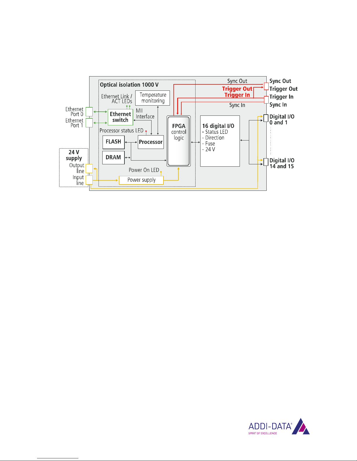
2.2 Block diagram
Fig. 2-1: MSX-E1516: Block diagram

Function description: Digital inputs/outputs MSX-E1516
3Function description: Digital inputs/outputs
The Ethernet system MSX-E1516 has 16 digital inputs or outputs for sensors or actuators.
3.1 Pin assignment
To each M12 female connector, up to two sensors or actuators can be connected. In addition, a 24 V
supply is available.
Table 3-1: Pin assignment: Digital inputs/outputs
Cable (black)
Pin No. Female connector,
5-pin, M12 Lead colour
1 24 V output brown
2 Digital I/O (2n+1)* white
3 GND blue
4 Digital I/O (2n)* black
5 not connected grey
* Please note that the female connector (n) is dual-wired and that the digital I/Os are determined via
(2n+1) or (2n) with 0 ≤n ≤7.
Examples:
Female connector 0 (n=0) –> Pin 2: (2 x 0 + 1) –> Digital I/O 1
–> Pin 4: (2 x 0) –> Digital I/O 0
Female connector 7 (n=7) –> Pin 2: (2 x 7 + 1) –> Digital I/O 15
–> Pin 4: (2 x 7) –> Digital I/O 14
www.addi-data.com 12
Function description: Digital inputs/outputs MSX-E1516
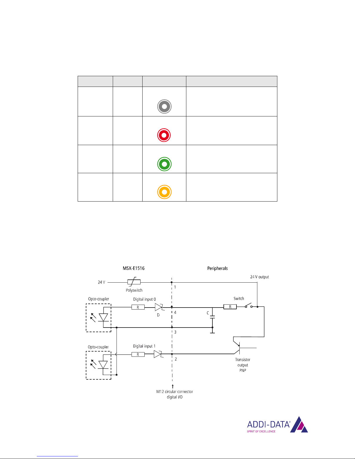
3.2 LED display
Table 3-2: LED display: Digital I/O
Direction Status LED Meaning
Output inactive No display
- No output active
- No voltage applied
Output active Lights red
- Output is active
- No voltage applied
Caution, risk of short-circuit!
Input inactive Lights green
- Input is ready for operation
- Signals can be received
Input active Lights yellow
- Input is active
- Signal is being received
3.3 Connection examples
3.3.1 Digital inputs (24 V)
Fig. 3-1: Connection example: Digital inputs (24 V)
www.addi-data.com 13
Function description: Digital inputs/outputs MSX-E1516
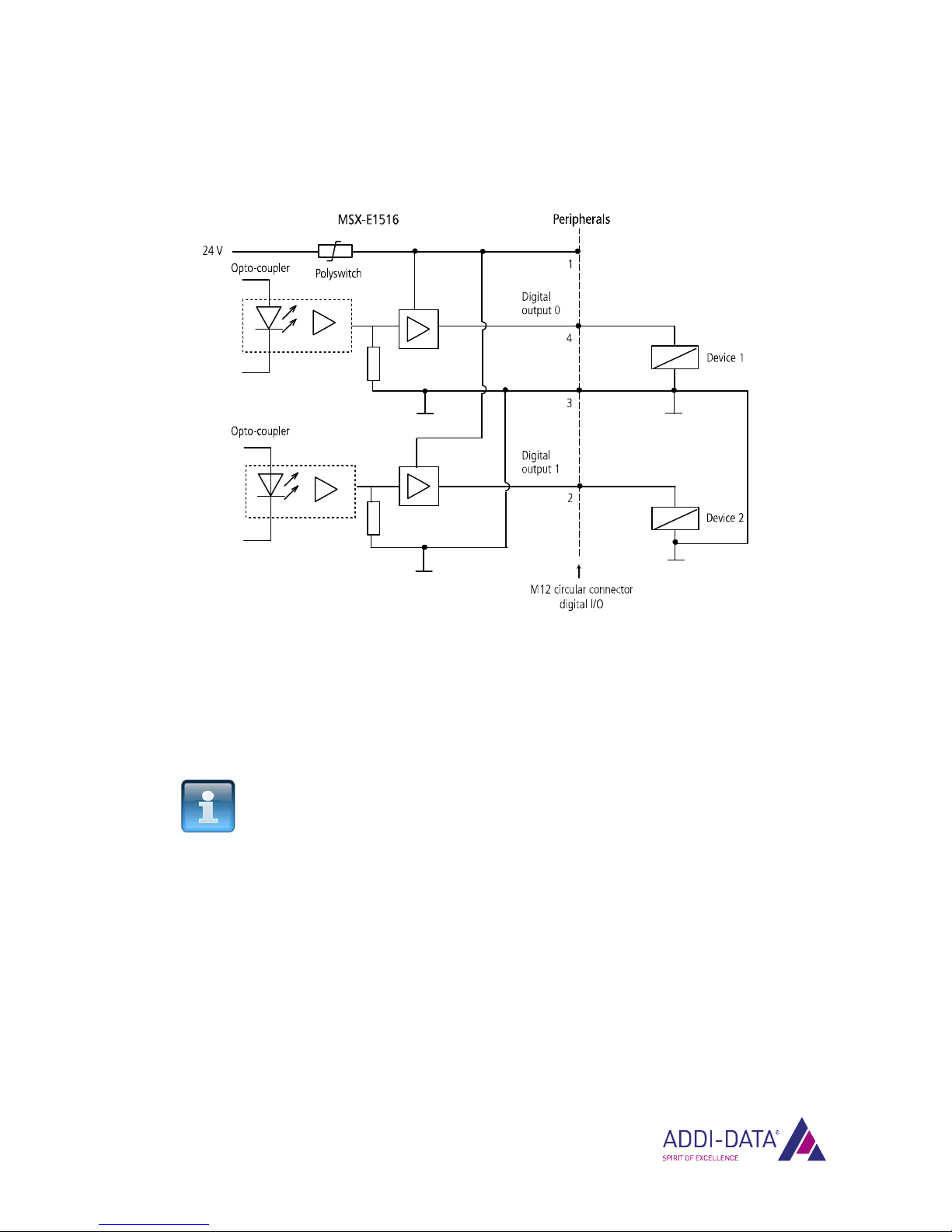
3.3.2 Digital outputs (24 V)
Fig. 3-2: Connection example: Digital outputs (24 V)
3.4 Digital outputs
By default, the digital channels of the MSX-E1516 are configured as inputs.
A port, i.e. a pair of channels can be configured as an output via the web interface of the MSX-E
system (see Chapter 4.1.1) or via the SOAP or Modbus function “DigitalIOInitPortConfiguration”.
NOTICE!
For each connector or port, only inputs or outputs can be
configured. In the event of a system reboot, the configuration is
only persistent if it has been changed on the web interface.
A port configured as an output is high-impedance. The status of the outputs can be read back by way
of control.
If a short-circuit occurs at a connected output, this output will be deactivated.
As soon as the short-circuit has been eliminated, a rearm has to be carried out to reactivate the output
(see Chapter 4.1.1). This means that the output is set to the status value that was programmed before
the short-circuit occurred. A new value can only be defined after the rearm event.
www.addi-data.com 14

Function description: Digital inputs/outputs MSX-E1516
3.5 Watchdog
The Ethernet system MSX-E1516 has a 16-bit watchdog, which is programmable in three time units
(μs, ms, s). The watchdog is used to reset the digital outputs to 0 V after a specific time.
Operation of the watchdog
1. After the system reboot, the watchdog is in “Uninitialised” state.
It can be initialised and activated (“Running” state) over the web interface of the MSX-E system or
by a software function.
2. With the first write access to the outputs, the watchdog is started: The watchdog time is loaded
and the watchdog starts counting down.
As long as the watchdog time has not elapsed, the watchdog is triggered with every further write
access to the outputs, i.e. the watchdog time is reloaded.
3. When the watchdog time has elapsed, the watchdog is put in “Overrun” state and all digital
outputs are set to 0 V or 0 mA. In “Overrun” state, any write access to the outputs is ignored.
4. To re-enable write access, the watchdog first has to be put in “Stopped” state (web interface) or
deactivated by a software function.
To reactivate the watchdog, it has to be put in “Running” state again or reinitialised and
reactivated by a software function.
3.6 Event logic
The event logic function (OR logic) enables event datagrams to be generated when the status of the
digital inputs or outputs changes.
On the web interface of the MSX-E system (see Chapter 4.1.1) or via the SOAP function
“MSXE1516__DigitalIOInitAndEnableEvent“, you can define the edge type of a specific channel for
which such a datagram should be generated.
When an event occurs, the Ethernet system provides the following information (see also Chapter 3.7):
•Time stamp (optional)
•“Source event mask”: Mask of the digital I/Os that generated the event
•“Digital I/O Status“: Status of the digital I/Os when the event occurred.
Example
For each rising edge of the digital I/O 0 and for each falling edge of the digital I/O 1, an event
datagram should be generated.
www.addi-data.com 15

Function description: Digital inputs/outputs MSX-E1516
Fig. 3-3: Event logic
NOTICE!
If the digital input filter is activated, the event logic may be
initialised only when the filter time has elapsed.
To avoid “false” events at the beginning of the application, a delay between the filter activation
(SOAP function “MSXE1516__DigitalIOSetInputFilterTime”) and the event logic initialisation (SOAP
function “MSXE1516__DigitalIOInitAndEnableEvent”) must be inserted. This delay should correspond
to the longest possible filter time, i.e. 65535 μs.
When the filter is activated, the digital inputs are internally set to 0. If they are externally switched to
24 V, for example, they will only be set to 1 again when the complete filter time has elapsed.
By configuring a digital output via the web interface, all other information from the “Digital I/O” page
including filter value and event logic is transferred to the MSX-E-System as well, and that at the same
time, i.e. without delay. Since the digital inputs are set to 0 during the whole filter time, a “false”
event is thus detected.
However, if you set an output directly via the SOAP function (e.g. sample in the CD directory
“MSX-E1516\SOAP\Samples \Windows\C#.NET_2005\ReadWrite”), no “false” events will occur.
www.addi-data.com 16

Function description: Digital inputs/outputs MSX-E1516
www.addi-data.com 17
3.7 Data format
Table 3-3: Data format: Digital I/O
tv_sec tv_usec Source event mask I/O status bitmap
4 bytes 4 bytes 4 bytes 4 bytes
Time stamp
(in s) low
(if data
format has
time stamp)
Time stamp
(in μs) high
(if data
format has
time stamp)
Mask of the event source:
- Bit 0-15: Status change of the channel
has generated the event
- Bit 16-28 = 0
- Bit 29: Event logic bit is set when the
status of the channel changes
- Bit 30: Synchro trigger has generated
the event
- Bit 31: Hardware trigger has
generated the event
The event may be generated by several
sources at the same time.
Status of the channels
after latching
Web interface: Quick access to the MSX-E system MSX-E1516
4Web interface: Quick access to the MSX-E system
4.1 “I/O Configuration”
In this manual, the function-specific pages of the MSX-E1516 web interface, which are located under
the menu item “I/O Configuration”, are described. For further information on the MSX-E web
interface, please refer to the general manual of the MSX-E systems (see PDF link).
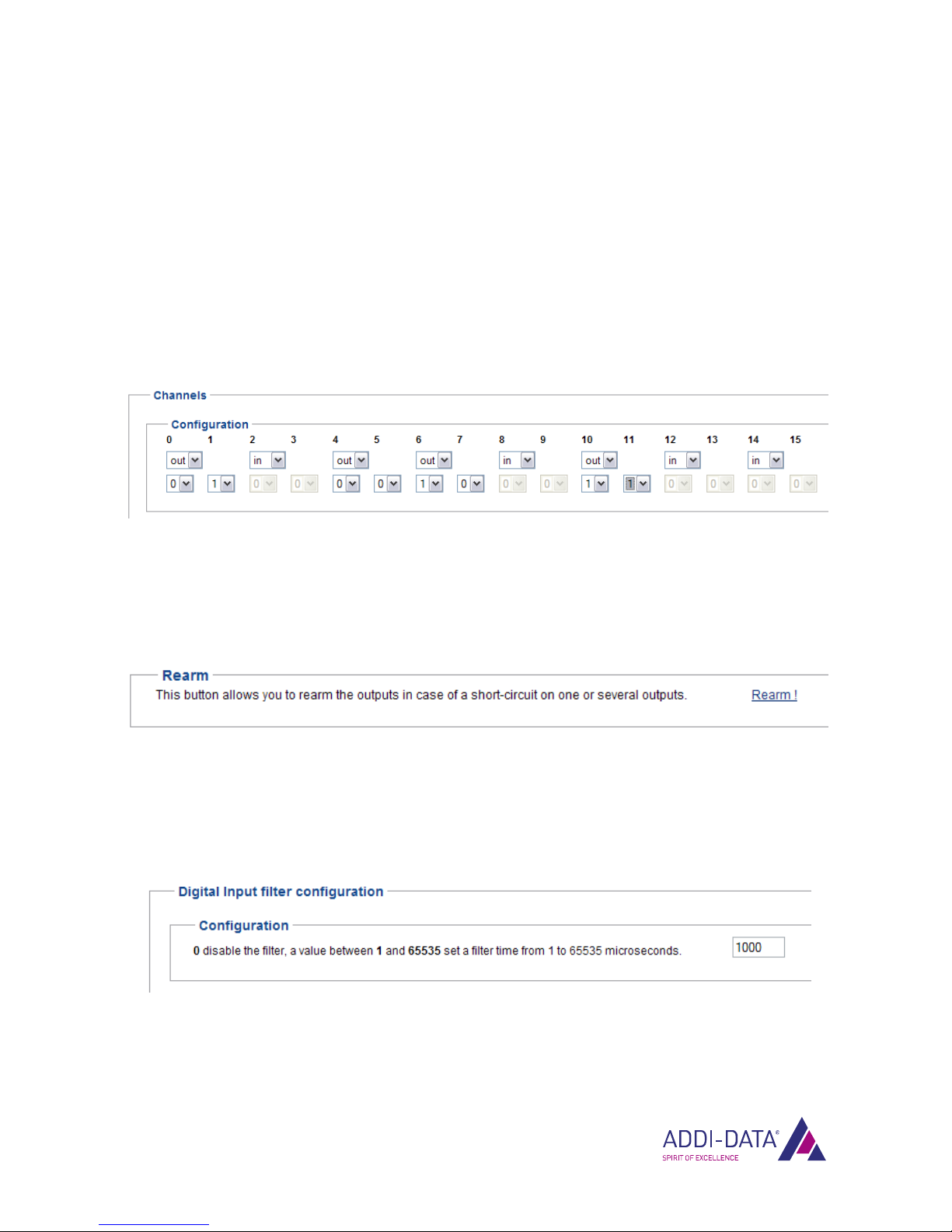
4.1.1 Menu item “Digital I/O”
Fig. 4-1: Digital I/O: Channels
On this page, you can configure the digital channels as pairs of inputs or outputs. For each output, also
the status (0 or 1) has to be defined.
Fig. 4-2: Channels: Rearm
After a short-circuit occurred, the required rearm (see Chapter 3.4) can be carried out via the
correspondent button.
Fig. 4-3: Digital I/O: Digital input filter configuration
For the digital inputs, a filter can be defined.
The filter time can be between 1 μs and 65535 μs. By entering the value 0, the filter will be
deactivated.
www.addi-data.com 18

Web interface: Quick access to the MSX-E system MSX-E1516
Fig. 4-4: Digital I/O: Digital Input/Output events
In this section, you can select for which channel and for which respective edge type an event datagram
should be generated.
In addition, a time stamp can be set for each event. The event logic is stopped via the corresponding
button.
NOTICE!
Please read Chapter 3.6 if you have activated the digital input
filter!
Fig. 4-5: Digital I/O: Digital Input/Output latch event
The current status of the digital inputs or outputs can be saved via the synchro trigger and be sent via
the data server. A time stamp is available as an option.
www.addi-data.com 19

Web interface: Quick access to the MSX-E system MSX-E1516
www.addi-data.com 20
4.1.2 Menu item “I/O Watchdog”
Fig. 4-6: I/O Watchdog: Current state
On this page, the current status of the watchdog for the digital inputs and outputs is displayed.
Fig. 4-7: I/O Watchdog: Configuration
You can configure the watchdog by defining the time unit and the watchdog time.
Table of contents
Other Addi-Data Network Hardware manuals


