Addi-Data MSX-E Series Parts list manual

DIN EN ISO 9001:2008 certified Edition: 02.05-07/2014
TECHNICAL
DESCRIPTION
MSX-Exxxx
Intelligent Ethernet system

Product information
This manual contains the technical installation and important instructions for correct commissioning
and usage, as well as production information according to the current status before printing.
The content of this manual and the technical product data may be changed without prior notice.
ADDI-DATA GmbH reserves the right to make changes to the technical data and the materials included
herein.
Warranty and liability
The user is not permitted to make changes to the product beyond the intended use, or to interfere
with the product in any other way.
ADDI-DATA shall not be liable for obvious printing and phrasing errors. In addition, ADDI DATA, if
legally permissible, shall not be liable for personal injury or damage to materials caused by improper
installation and/or commissioning of the product by the user or improper use, for example, if the
product is operated despite faulty safety and protection devices, or if notes in the operating
instructions regarding transport, storage, installation, commissioning, operation, thresholds, etc. are
not taken into consideration. Liability is further excluded if the operator changes the product or the
source code files without authorisation and/or if the operator is guilty of not monitoring the
permanent operational capability of working parts and this has led to damage.
Copyright
This manual, which is intended for the operator and its staff only, is protected by copyright.
Duplication of the information contained in the operating instructions and of any other product
information, or disclosure of this information for use by third parties, is not permitted, unless this right
has been granted by the product licence issued. Non-compliance with this could lead to civil and
criminal proceedings.
ADDI-DATA software product licence
Please read this licence carefully before using the standard software. The customer is only granted the
right to use this software if he/she agrees with the conditions of this licence.
The software must only be used to set up the ADDI-DATA products.
Reproduction of the software is forbidden (except for back-up and for exchange of faulty data
carriers). Disassembly, decompilation, decryption and reverse engineering of the software are
forbidden. This licence and the software may be transferred to a third party if this party has acquired a
product by purchase, has agreed to all the conditions in this licence contract and the original owner
does not keep any copies of the software.
Trademarks
•ADDI-DATA, APCI-1500, MSX-Box and MSX-E are registered trademarks of ADDI-DATA GmbH.
•Turbo Pascal, Delphi, Borland C, Borland C++ are registered trademarks of Borland Software
Corporation.
•Microsoft .NET, Microsoft C, Visual C++, MS-DOS, Windows 95, Windows 98, Windows 2000,
Windows NT, Windows EmbeddedNT, Windows XP, Windows Vista, Windows 7, Windows Server
2000, Windows Server 2003, Windows Embedded and Internet Explorer are registered trademarks
of Microsoft Corporation.
•LabVIEW, LabWindows/CVI, DASYLab, DIAdem are registered trademarks of National Instruments
Corporation.
•CompactPCI is a registered trademark of PCI Industrial Computer Manufacturers Group.
•VxWorks is a registered trademark of Wind River Systems, Inc.
•RTX is a registered trademark of IntervalZero.
•Mozilla Firefox is a registered trademark of Mozilla Foundation.
•SIMATIC S7 is a registered trademark of Siemens AG.
www.addi-data.com 2

Warning!
The following risks result from the improper implementation of the
Ethernet system and from use contrary to the regulations:
Personal injury
Damage to the Ethernet system, the PC and peripherals
Pollution of the environment.
Protect yourself, others and the environment!
Read the safety precautions (yellow leaflet) carefully!
If this leaflet is not enclosed with the documentation, please contact us
and ask for it.
Observe the instructions of this manual!
Make sure that you do not forget or skip any step!
We are not liable for damages resulting from the wrong use of the
Ethernet system.
Pay attention to the following symbols:
NOTICE!
Designates hints and other useful information.
NOTICE!
Designates a possibly dangerous situation.
If the instructions are ignored, the Ethernet system, the PC and/or
peripherals may be destroyed.
WARNING!
Designates a possibly dangerous situation.
If the instructions are ignored, the Ethernet system, the PC and/or
peripherals may be destroyed and persons may be endangered.
www.addi-data.com 3

Contents MSX-Exxxx
Contents
Warning! ...........................................................................................................................................3
Chapter overview.............................................................................................................................7
1Mounting and connection....................................................................................................8
1.1 Commissioning of the Ethernet system (overview) ............................................................................8
1.2 Fixing the Ethernet system.................................................................................................................10
1.2.1 Mounting on a DIN rail ......................................................................................................................10
1.2.2 Angle bracket mounting ....................................................................................................................11
1.3 Pin assignment ....................................................................................................................................13
1.3.1 Ethernet ports .....................................................................................................................................14
1.3.2 Trigger/synchro ...................................................................................................................................15
1.3.3 Voltage supply ....................................................................................................................................16
1.4 Connecting peripherals ......................................................................................................................17
1.4.1 Ethernet ports .....................................................................................................................................17
1.4.2 Trigger and synchro signals................................................................................................................18
1.4.3 Voltage supply ....................................................................................................................................18
1.4.4 Sensors or actuators............................................................................................................................18
1.5 Connecting several Ethernet systems (cascading) ............................................................................19
1.6 LED display ..........................................................................................................................................20
1.6.1 Overview..............................................................................................................................................20
1.6.2 “Status” LED........................................................................................................................................21
2Software tool “ConfigTools” .............................................................................................23
2.1 First steps .............................................................................................................................................23
2.2 Main window structure ......................................................................................................................24
2.2.1 Menu bar .............................................................................................................................................24
2.2.2 ConfigTools Explorer ..........................................................................................................................25
2.2.3 Actions .................................................................................................................................................26
3Function description: General functions...........................................................................28
3.1 Hardware trigger ................................................................................................................................28
3.2 Synchronisation and time stamp .......................................................................................................29
3.2.1 Synchronisation...................................................................................................................................29
3.2.2 Master and slaves................................................................................................................................29
3.2.3 Time stamp ..........................................................................................................................................29
3.2.4 Time and date .....................................................................................................................................29
3.3 Temperature monitoring ...................................................................................................................30
3.4 Customer key (security feature).........................................................................................................30
4Web interface: Quick access to the MSX-E system ...........................................................32
4.1 Login ....................................................................................................................................................32
4.2 Navigation ...........................................................................................................................................33
4.3 “System”..............................................................................................................................................33
4.3.1 Menu item “Information”..................................................................................................................33
4.3.2 Menu item “Diagnosis”......................................................................................................................34
4.3.3 Menu item “Security”.........................................................................................................................37
4.3.4 Menu item “Reboot” or “Shutdown”...............................................................................................41
4.4 „Network“...........................................................................................................................................42
4.4.1 Menu item “Configuration” ..............................................................................................................42
4.5 „I/O Configuration“............................................................................................................................43
4.5.1 Menu item “Synchro timer”...............................................................................................................43
4.5.2 Menu item “Hardware trigger”.........................................................................................................43
4.5.3 “Configuration management” ..........................................................................................................43
4.5.4 “Autostart” (Automatic configuration start) ...................................................................................44
4.6 „Development Mode“........................................................................................................................44
4.7 “Data server” ......................................................................................................................................45
www.addi-data.com 4

Contents MSX-Exxxx
4.7.1 “Network protocol”............................................................................................................................45
4.7.2 „Blocking TCP/IP transfer“ .................................................................................................................46
4.7.3 “Data caching”....................................................................................................................................46
4.7.4 Save and Restart..................................................................................................................................49
4.8 “Modbus server”.................................................................................................................................49
5Software ..............................................................................................................................50
5.1 MSX-E system interface ......................................................................................................................50
5.2 Access via SOAP/web service ..............................................................................................................51
5.2.1 SOAP definition...................................................................................................................................51
5.2.2 SOAP functions....................................................................................................................................51
5.3 Access via Open Modbus (for PLC).....................................................................................................51
5.4 Data server ..........................................................................................................................................52
5.5 Event server .........................................................................................................................................52
5.5.1 Packet format......................................................................................................................................52
5.5.2 Time stamp format .............................................................................................................................53
6Returning or disposing .......................................................................................................54
6.1 Returning.............................................................................................................................................54
6.2 Disposal of ADDI-DATA devices .........................................................................................................55
7Appendix .............................................................................................................................56
7.1 Glossary................................................................................................................................................56
7.2 Index ....................................................................................................................................................58
8Contact and support ...........................................................................................................59
Figures
Fig. 1-1: Commissioning (overview) .............................................................................................................8
Fig. 1-2: Type label ........................................................................................................................................9
Fig. 1-3: Fastening clips...............................................................................................................................10
Fig. 1-4: Brackets pointing outwards.........................................................................................................11
Fig. 1-5: Brackets pointing inwards............................................................................................................11
Fig. 1-6: Angle bracket mounting ..............................................................................................................12
Fig. 1-7: Mounting set: Seal and screw (short)..........................................................................................12
Fig. 1-8: Mounting set: Original screw, seal and screw (long) .................................................................12
Fig. 1-9: Connectors.....................................................................................................................................13
Fig. 1-10: Connect peripherals......................................................................................................................17
Fig. 1-11: MSX-Exxxx: Connect sensors or actuators (example) .................................................................18
Fig. 1-12: Connect several Ethernet systems ...............................................................................................19
Fig. 2-1: ConfigTools: Scan MSX-E systems ................................................................................................23
Fig. 2-2: ConfigTools: Main window ..........................................................................................................24
Fig. 2-3: ConfigTools: MSX-E search...........................................................................................................25
Fig. 2-4: ConfigTools: Action buttons ........................................................................................................26
Fig. 3-1: Example of a trigger.....................................................................................................................29
Fig. 4-1: MSX-E web interface: Login window ..........................................................................................32
Fig. 4-2: MSX-E web interface: Homepage................................................................................................33
Fig. 4-3: MSX-E web interface: “System diagnosis”..................................................................................34
Fig. 4-4: Diagnosis: Subsystem state...........................................................................................................34
Fig. 4-5: Diagnosis: Real Time Clock...........................................................................................................35
Fig. 4-6: Diagnosis: Resources.....................................................................................................................35
Fig. 4-7: Diagnosis: Inter-module synchronisation....................................................................................35
Fig. 4-8: Diagnosis: Process list ...................................................................................................................36
Fig. 4-9: Diagnosis: Mounts ........................................................................................................................36
Fig. 4-10: “Security”: Enter new password..................................................................................................37
www.addi-data.com 5

Contents MSX-Exxxx
www.addi-data.com 6
Fig. 4-11: “Security”: TLS encryption ...........................................................................................................38
Fig. 4-12: “Security”: Remote call “SetTime()” ...........................................................................................39
Fig. 4-13: “Security”: Remote calls “autoconf/autostart” ..........................................................................39
Fig. 4-14: ”Security”: General system configuration ..................................................................................40
Fig. 4-15: “Security”: Remote commands....................................................................................................41
Fig. 4-16: Reboot: Action ..............................................................................................................................41
Fig. 4-17: Shutdown: Action .........................................................................................................................41
Fig. 4-18: Configuration: Network configuration.......................................................................................42
Fig. 4-19: Configuration: Syslog (network logging) ...................................................................................42
Fig. 4-20: I/O Configuration: Configuration management.........................................................................43
Fig. 4-21: Data server: Network protocol ....................................................................................................45
Fig. 4-22: Data server: Blocking TCP/IP transfer ..........................................................................................46
Fig. 4-23: Data server: Data caching ............................................................................................................46
Fig. 4-24: Ring buffer ....................................................................................................................................48
Fig. 4-25: Data server: What do you want to do?.......................................................................................49
Fig. 5-1: Overview: Servers..........................................................................................................................50
Fig. 5-2: SOAP in the TCP/IP protocol stack ...............................................................................................51
Fig. 6-1: Serial number................................................................................................................................54
Fig. 6-2: Disposal: Labelling ........................................................................................................................55
Tables
Table 1-1: Pin assignment: Ethernet ports 0 and 1 ......................................................................................14
Table 1-2: Pin assignment: Trigger/synchro..................................................................................................15
Table 1-3: Trigger/synchro cables ..................................................................................................................15
Table 1-4: Pin assignment: Voltage supply...................................................................................................16
Table 1-5: LED display ....................................................................................................................................20
Table 1-6: “Status” LED..................................................................................................................................21
Table 3-1: Temperature monitoring: MSX-Exxxx .........................................................................................30
Table 3-2: Temperature monitoring: MSX-E3700 and MSX-E3701 .............................................................30
Table 3-3: Customer key ................................................................................................................................30
Table 5-1: MSX-E servers ................................................................................................................................50
Table 5-2: Event server: Packet format .........................................................................................................52

Chapter overview MSX-Exxxx
Chapter overview
In this manual, you will find the following information:
Chapter Content
1 Information on mounting the MSX-E system, pin assignments, the connection of
peripherals and the system’s LED display
2 Description of the software tool “ConfigTools” (required, for example, to adapt the
IP address of the MSX-E system when using the system for the first time)
3 Description of general functions (e.g. Customer Key)
4 Description of the web interface of the MSX-E system for fast access to the system
without programming
5 Software description: Access over SOAP/web service or Open Modbus (for PLC)
6 Procedure for returning (repairing, etc.) or disposing of the MSX-E system
7 Appendix with glossary and index
8 Contact and support address
www.addi-data.com 7

Mounting and connection MSX-Exxxx
1Mounting and connection
1.1 Commissioning of the Ethernet system (overview)
Fig. 1-1: Commissioning (overview)
Risk of injury!
Please follow the safety precautions! An improper handling of the
Ethernet system may cause property damage and injury.
Discharge any static by touching an earth wire.
Remove the Ethernet system from its protective packaging.
Check the type label on the bottom side of the Ethernet system to know if the system corresponds
to your requested version.
www.addi-data.com 8

Mounting and connection MSX-Exxxx
Fig. 1-2: Type label
Serial
number
Disposal label
Version
Product name
Customisation
Supply voltage
Nominal
voltage
Current
consumption
The type label contains, for example, the product name including the specific version name, and the
serial number of the Ethernet system. In case of queries, these details always have to be kept at hand!
For more information on the disposal label, see Chapter 6.2.
Information on cables and other accessories can be found in the accessories list of the MSX-E systems.
www.addi-data.com 9
Mounting and connection MSX-Exxxx
www.addi-data.com 10
1.2 Fixing the Ethernet system
1.2.1 Mounting on a DIN rail
With the mounting set MX-Rail1(see document “MSX-E Accessories“), you can attach the Ethernet
system to a DIN rail.
Risk of injury!
If you have already mounted this Ethernet system on a DIN rail and
want to transport it in a switch cabinet or in other systems, please
ensure that it is adequately secured for transport!
The Ethernet system could, for example, fall off the DIN rail, which
could cause damage to the Ethernet system and/or other objects
or injury of persons.
Mount the Ethernet system on the DIN rail by inserting the clips with the springs under the DIN
rail.
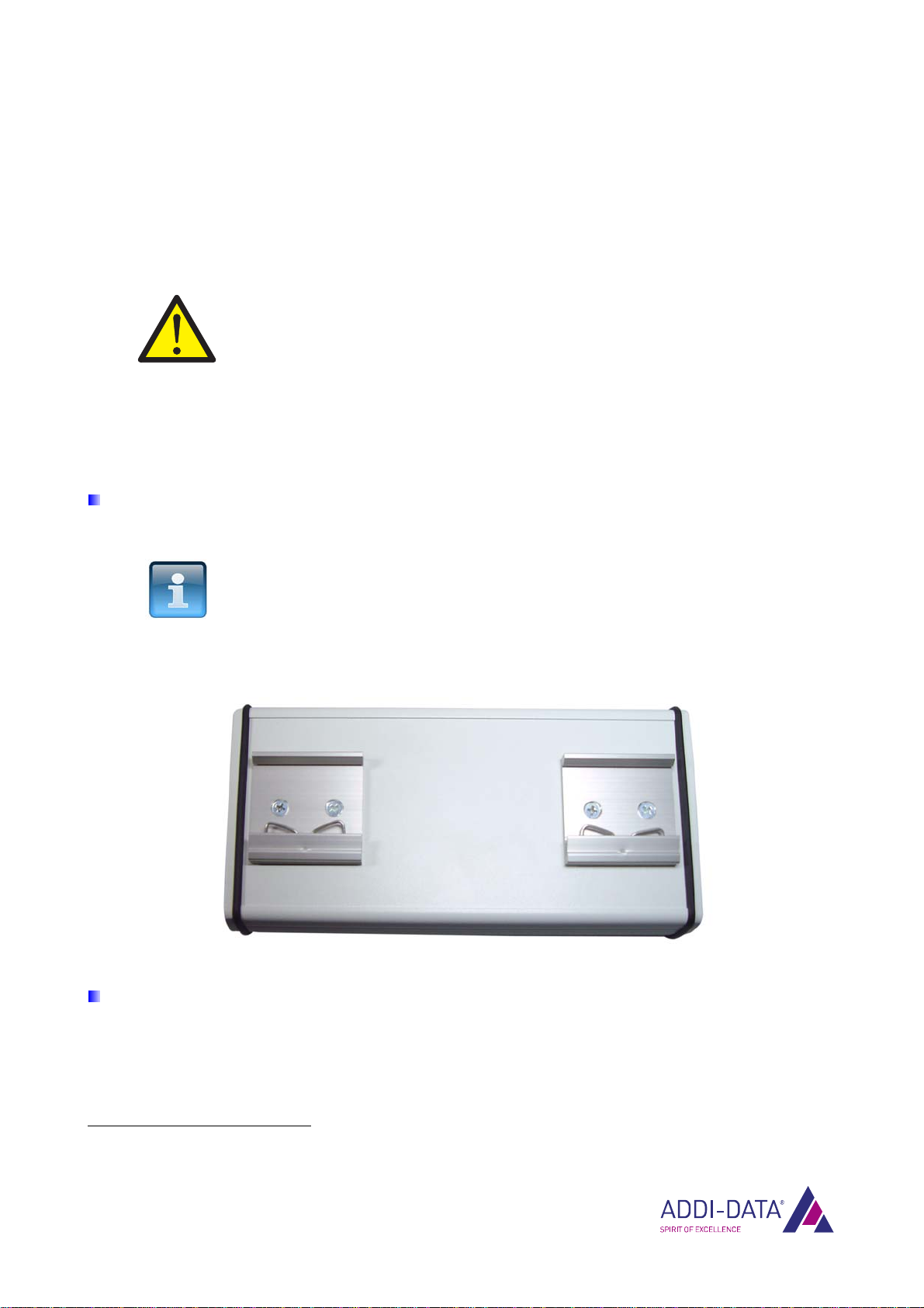
NOTICE!
The spring in the fastening clips points to the bottom of the
housing (see the following figure).
Fig. 1-3: Fastening clips
Push the Ethernet system as much as possible up and then backwards until the top of the fastening
clips engages with the DIN rail.
1Please specify when ordering the Ethernet system!

Mounting and connection MSX-Exxxx
1.2.2 Angle bracket mounting
With the mounting set MX-Screw (see document “MSX-E Accessories“), you can fit the Ethernet
system for direct attachment to machines or other devices.
According to your requirements, you can fix all four brackets pointing either outwards or inwards.
Fig. 1-4: Brackets pointing outwards
Fig. 1-5: Brackets pointing inwards
To mount the brackets, proceed as follows:
NOTICE!
The housing of the Ethernet system must not be opened or the
warranty claim will be invalid (see also the system-specific MSX-E
manual, Chapter 1.2.4)!
For this reason, the housing part to which the angle brackets are
fixed has to be in a horizontal position during mounting to prevent
it from loosening from the entire housing.
If the Ethernet system cannot be positioned in this way, the
respective housing part has to be pushed towards the inside of the
system during the whole mounting process so that the housing
remains closed (see the following figure).
www.addi-data.com 11

Mounting and connection MSX-Exxxx
Fig. 1-6: Angle bracket mounting
Loosen the screws at the side of the Ethernet system.
For the remainder of the mounting process, please use only the short seals and screws from the
mounting set.
Fig. 1-7: Mounting set: Seal and screw (short)
The original screw from the MSX-E system and the long seals or screws from the mounting set must
not be used any longer.
Fig. 1-8: Mounting set: Original screw, seal and screw (long)
www.addi-data.com 12
Mounting and connection MSX-Exxxx
Place a seal in one of the screw holes.
Place the bracket on the seal.
Fix the bracket with a short screw from the mounting set.
Repeat these steps with the other screw holes.
Once you have mounted the brackets on the Ethernet system, you can attach the system directly to
other devices or machines by using other screws.
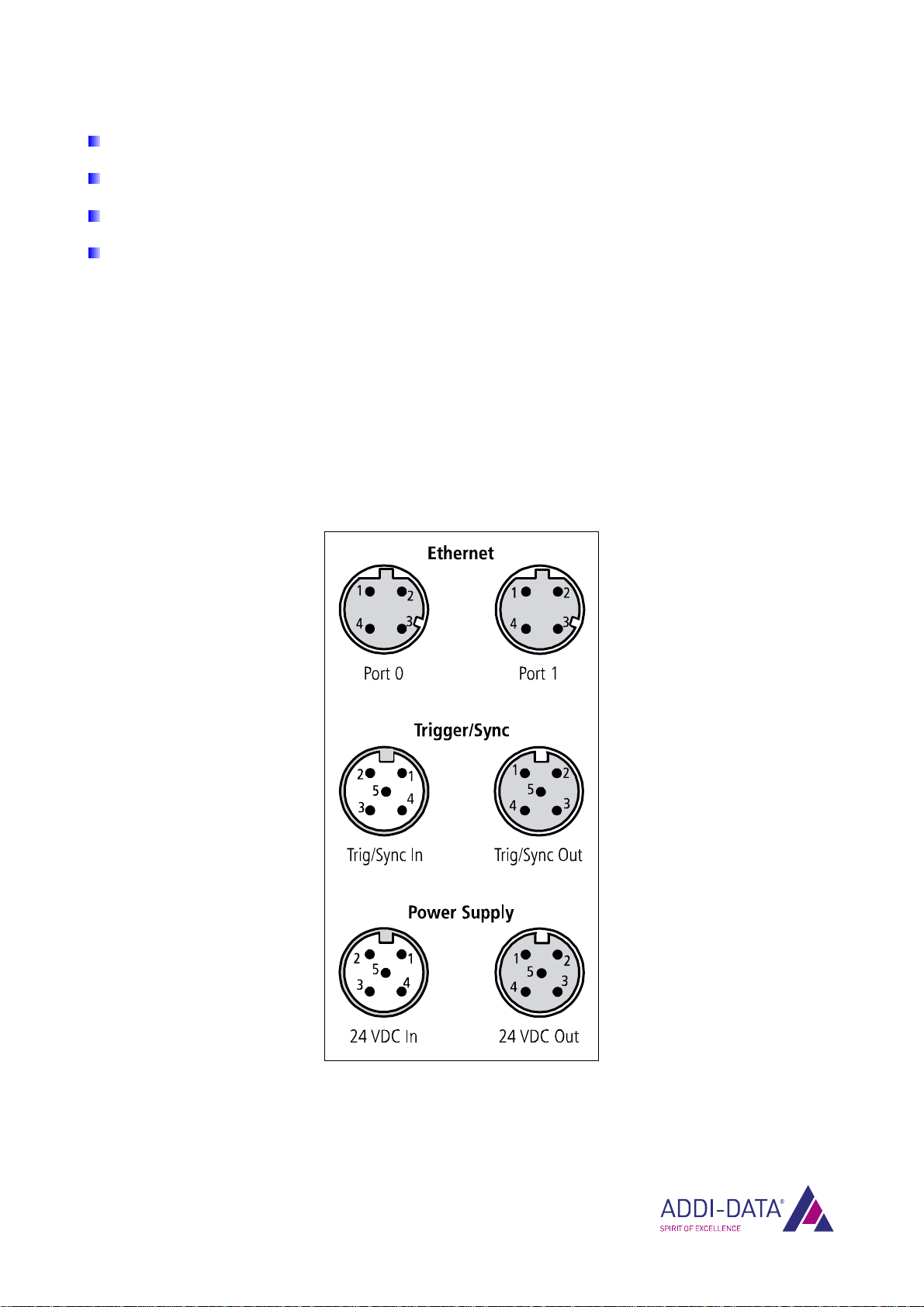
1.3 Pin assignment
In this chapter, you will find the pin assignments of the connectors for Ethernet, trigger/synchro and
the voltage supply of the Ethernet system MSX-Exxxx.
Fig. 1-9: Connectors
www.addi-data.com 13
Mounting and connection MSX-Exxxx
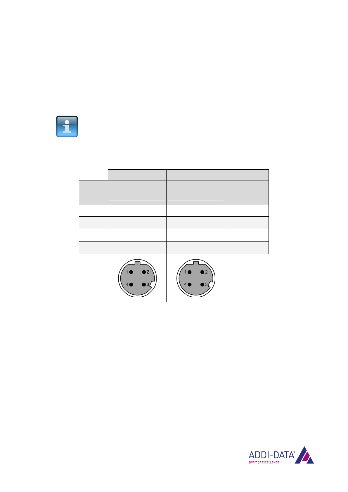
1.3.1 Ethernet ports
In order to access the MSX-E system, you have to connect one of the Ethernet interfaces (Port 0 or
Port 1) to your PC. For this, you can use a CMX-6x cable.
To cascade the MSX-E systems with one another, you need a CMX-7x cable.
The LED display “Port 0 ACT/Link” or “Port 1 ACT/Link” gives you information on the status of the
corresponding interface. For more details, see Chapter 1.6.1.
NOTICE!
The LED display only works if the MSX-E system is connected to
the voltage supply.
Table 1-1: Pin assignment: Ethernet ports 0 and 1
Ethernet Port 0 Ethernet Port 1 Cable (green)
Pin No. Female connector,
D-coded, M12
Female connector,
D-coded, M12 Lead colour
1 TD0+ TD1+ yellow
2 RD0+ RD1+ white
3 TD0- TD1- orange
4 RD0- RD1- blue
www.addi-data.com 14

Mounting and connection MSX-Exxxx
1.3.2 Trigger/synchro
Table 1-2: Pin assignment: Trigger/synchro
Trigger/Sync In
Trigger/Sync Out Cable (purple)
Pin No. Connector,
5-pin, M12
Female connector,
5-pin, M12
Lead
colour
Lead
pair
1 Trigger input - Trigger input - blue
2 Trigger input + Trigger input + white
1
3 Synchro input + Synchro output + red
4 Synchro input - Synchro output - black
2
5 Ground Ground
Please use a shielded trigger/synchro cable.
Table 1-3: Trigger/synchro cables
Name Cable end Length
CMX-40 Open end / female connector, 5-pin 1.5 m
CMX-41 Open end / female connector, 5-pin 3 m
CMX-42 Open end / female connector, 5-pin 5 m
CMX-43 Open end / female connector, 5-pin 10 m
CMX-49 Open end / female connector, 5-pin on request
CMX-50 Male connector, 5-pin / female connector, 5-pin
1.5 m
CMX-51 Male connector, 5-pin / female connector, 5-pin
3 m
CMX-52 Male connector, 5-pin / female connector, 5-pin
5 m
CMX-59 Male connector, 5-pin / female connector, 5-pin
on request
CMX-59_0,3
Male connector, 5-pin / female connector, 5-pin
0.3 m
www.addi-data.com 15

Mounting and connection MSX-Exxxx
1.3.3 Voltage supply
Table 1-4: Pin assignment: Voltage supply
Power Supply In
Power Supply Out Cable
(black)
Pin No.
Connector,
5-pin, M12
Female connector,
5-pin, M12 Lead colour
1 24 V 24 V brown
2 24 V 24 V white
3 Ground Ground blue
4 Ground Ground black
5 not connected not connected grey
www.addi-data.com 16

Mounting and connection MSX-Exxxx
www.addi-data.com 17
1.4 Connecting peripherals
Discharge any static by touching an earth wire.
Remove the Ethernet system from its protective packaging.
Information on cables and other accessories can be found in the accessories list of the MSX-E systems.
1.4.1 Ethernet ports
Plug the Ethernet cable into Ethernet Port 02.
Fig. 1-10: Connect peripherals
2If you want to connect several Ethernet systems, please read Chapter 1.5.
Ethernet Port 0
Trig/Sync In
Current supply input
(24 VDC In)
Current supply output
(24 VDC Out)

Mounting and connection MSX-Exxxx
www.addi-data.com 18
1.4.2 Trigger and synchro signals
Plug the cable into the connector “Trig/Sync In”3(see Fig. 1-10).
1.4.3 Voltage supply
Plug the cable into the input “24 VDC In”1(see Fig. 1-10).
1.4.4 Sensors or actuators
Information concerning the type of sensor or actuator, the corresponding pin assignment as well as
connection examples can be found in the respective system-specific MSX-E manual.
Fig. 1-11: MSX-Exxxx: Connect sensors or actuators (example)
3If you want to connect several Ethernet systems, please read Chapter 1.5.

Mounting and connection MSX-Exxxx
1.5 Connecting several Ethernet systems (cascading)
You have the possibility to connect several Ethernet systems to the MSX-Exxxx. In order to do so,
proceed as follows:
Connect the first Ethernet system (see description at the beginning of this chapter).
Connect the components according to the following figure.
Fig. 1-12: Connect several Ethernet systems
www.addi-data.com 19

Mounting and connection MSX-Exxxx
1.6 LED display
1.6.1 Overview
The LEDs give you the following information:
Table 1-5: LED display
LED Display Meaning
Lights white
The system is ready for
operation.
ADDI-DATA logo
No display
ADDI- DATA®
The system is in energy-
saving mode.
No display
There is no voltage applied.
Power On
Lights green
Voltage is applied.
The system is ready for
operation.
No display
There is no network
connection.
Lights yellow
Port 0 ACT/Link
or
Port 1 ACT/Link
Flashes yellow
The Ethernet cable is
connected to Port 0 or 1.
The network connection is
established.
Status Lights green
Fur further display
settings, see the
following table.
The system is ready for
operation.
www.addi-data.com 20
Table of contents
Other Addi-Data Network Hardware manuals


Popular Network Hardware manuals by other brands


ATTO Technology
ATTO Technology FibreBridge 2370E Installation and operation manual

Worldcast Systems
Worldcast Systems RELIO user manual

Risco
Risco Agility Software manual

HeimVision
HeimVision HM243 user manual

Control Techniques
Control Techniques FM-3 Reference manual

INSIGHT
INSIGHT DLP DIRECTOR 2200 Hardware installation guide