Addi-Data MSX-E1701 Parts list manual

DIN EN ISO 9001:2008 certified Edition: 02.02-08/2012
TECHNICAL
DESCRIPTION
MSX-E1701
Ethernet multifunction counter system

Product information
This manual contains the technical installation and important instructions for correct commissioning
and usage, as well as production information according to the current status before printing.
The content of this manual and the technical product data may be changed without prior notice.
ADDI-DATA GmbH reserves the right to make changes to the technical data and the materials included
herein.
Warranty and liability
The user is not permitted to make changes to the product beyond the intended use, or to interfere
with the product in any other way.
ADDI-DATA shall not be liable for obvious printing and phrasing errors. In addition, ADDI DATA, if
legally permissible, shall not be liable for personal injury or damage to materials caused by improper
installation and/or commissioning of the product by the user or improper use, for example, if the
product is operated despite faulty safety and protection devices, or if notes in the operating
instructions regarding transport, storage, installation, commissioning, operation, thresholds, etc. are
not taken into consideration. Liability is further excluded if the operator changes the product or the
source code files without authorisation and/or if the operator is guilty of not monitoring the
permanent operational capability of working parts and this has led to damage.
Copyright
This manual, which is intended for the operator and its staff only, is protected by copyright.
Duplication of the information contained in the operating instructions and of any other product
information, or disclosure of this information for use by third parties, is not permitted, unless this right
has been granted by the product licence issued. Non-compliance with this could lead to civil and
criminal proceedings.
ADDI-DATA software product licence
Please read this licence carefully before using the standard software. The customer is only granted the
right to use this software if he/she agrees with the conditions of this licence.
The software must only be used to set up the ADDI-DATA products.
Reproduction of the software is forbidden (except for back-up and for exchange of faulty data
carriers). Disassembly, decompilation, decryption and reverse engineering of the software are
forbidden. This licence and the software may be transferred to a third party if this party has acquired a
product by purchase, has agreed to all the conditions in this licence contract and the original owner
does not keep any copies of the software.
Trademarks
•ADDI-DATA, APCI-1500, MSX-Box and MSX-E are registered trademarks of ADDI-DATA GmbH.
•Turbo Pascal, Delphi, Borland C, Borland C++ are registered trademarks of Borland Software
Corporation.
•Microsoft .NET, Microsoft C, Visual C++, MS-DOS, Windows 95, Windows 98, Windows 2000,
Windows NT, Windows EmbeddedNT, Windows XP, Windows Vista, Windows 7, Windows Server
2000, Windows Server 2003, Windows Embedded and Internet Explorer are registered trademarks
of Microsoft Corporation.
•LabVIEW, LabWindows/CVI, DASYLab, DIAdem are registered trademarks of National Instruments
Corporation.
•CompactPCI is a registered trademark of PCI Industrial Computer Manufacturers Group.
•VxWorks is a registered trademark of Wind River Systems, Inc.
•RTX is a registered trademark of IntervalZero.
•Mozilla Firefox is a registered trademark of Mozilla Foundation.
•SIMATIC S7 is a registered trademark of Siemens AG.
www.addi-data.com 2

Warning
The following risks result from improper implementation and from use of the
Ethernet system contrary to the regulations:
Personal injury
Damage to the Ethernet system, the PC and peripherals
Pollution of the environment
Protect yourself, others and the environment!
Read the safety precautions (yellow leaflet) carefully!
If this leaflet is not enclosed with the documentation, please contact us
and ask for it.
Observe the instructions of this manual!
Make sure that you do not forget or skip any step. We are not liable for
damages resulting from a wrong use of the Ethernet system.
Pay attention to the following symbols:
i IMPORTANT!
Designates hints and other useful information.
WARNING!
Designates a possibly dangerous situation.
If the instructions are ignored, the Ethernet system, the PC and/or
peripherals may be destroyed.
WARNING!
Designates a possibly dangerous situation.
If the instructions are ignored, the Ethernet system, the PC and/or
peripherals may be destroyed and persons may be endangered.
www.addi-data.com 3

Contents MSX-E1701
Contents
Warning.............................................................................................................................................3
Chapter overview.............................................................................................................................6
1Definition of application, user, handling ...........................................................................7
1.1 Definition of application......................................................................................................................7
1.1.1 Intended use..........................................................................................................................................7
1.1.2 Usage restrictions..................................................................................................................................7
1.1.3 Limits of use ..........................................................................................................................................7
1.2 Safety precautions ................................................................................................................................7
1.2.1 Current sources .....................................................................................................................................7
1.2.2 Degrees of protection ..........................................................................................................................7
1.2.3 Cables.....................................................................................................................................................8
1.2.4 Housing..................................................................................................................................................8
1.3 User ........................................................................................................................................................8
1.3.1 Qualification..........................................................................................................................................8
1.3.2 Country-specific regulations ................................................................................................................8
1.4 Handling of the Ethernet system.........................................................................................................9
1.5 Questions and updates.........................................................................................................................9
2Brief description..................................................................................................................10
2.1 Functions and features .......................................................................................................................10
2.2 Block diagram .....................................................................................................................................11
3Function description: Incremental counter inputs...........................................................12
3.1 Pin assignment ....................................................................................................................................12
3.2 Selecting the supply voltage ..............................................................................................................14
3.3 Connection example...........................................................................................................................15
3.4 TTL signal to RS422 input ...................................................................................................................16
3.5 Acquisition modes...............................................................................................................................16
3.5.1 Options ................................................................................................................................................18
3.6 Frequency measurement ....................................................................................................................18
3.7 Compare logic .....................................................................................................................................18
3.8 Index and reference point logic.........................................................................................................19
3.9 Hardware trigger ................................................................................................................................19
3.10 Digital filter for the incremental counter inputs..............................................................................20
4Function description: Digital inputs/outputs....................................................................21
4.1 Pin assignment ....................................................................................................................................21
4.2 LED display ..........................................................................................................................................22
4.3 Connection examples..........................................................................................................................23
4.3.1 Digital inputs (24 V)............................................................................................................................23
4.3.2 Digital outputs (24 V) .........................................................................................................................24
4.4 Digital outputs ....................................................................................................................................24
4.5 Watchdog ............................................................................................................................................25
5Function description: PWM outputs ..................................................................................26
5.1 Pin assignment ....................................................................................................................................26
6Web interface: Quick access to the MSX-E system ...........................................................27
6.1 “I/O Configuration”............................................................................................................................27
6.1.1 Menu item “Digital I/O”.....................................................................................................................27
6.1.2 Menu item “I/O Watchdog”...............................................................................................................27
6.1.3 Menu item “Incremental counter”....................................................................................................28
6.1.4 Menu item “PWM”.............................................................................................................................29
6.1.5 Data format.........................................................................................................................................30
7Technical data and limit values .........................................................................................31
7.1 Electromagnetic compatibility (EMC)................................................................................................31
7.2 Mechanical structure ..........................................................................................................................31
www.addi-data.com 4

Contents MSX-E1701
www.addi-data.com 5
7.3 Versions ...............................................................................................................................................32
7.4 Limit values..........................................................................................................................................32
7.4.1 Ethernet...............................................................................................................................................33
7.4.2 Trigger input .......................................................................................................................................33
7.4.3 Synchro input and output ..................................................................................................................33
7.4.4 Incremental counter inputs................................................................................................................34
7.4.5 PWM ....................................................................................................................................................34
7.4.6 Digital inputs.......................................................................................................................................34
7.4.7 Digital outputs ....................................................................................................................................35
7.4.8 Watchdog ............................................................................................................................................35
8Appendix .............................................................................................................................36
8.1 Glossary................................................................................................................................................36
8.2 Index ....................................................................................................................................................39
9Contact and support ...........................................................................................................40
Figures
Fig. 1-1: Correct handling .............................................................................................................................9
Fig. 2-1: MSX-E1701: Block diagram ..........................................................................................................11
Fig. 3-1: MSX-E1701: Right-hand side of the housing ..............................................................................14
Fig. 3-2: 24 V supply: Jumper at positions 1 and 2....................................................................................14
Fig. 3-3: 5 V supply: Jumper at positions 2 and 3......................................................................................15
Fig. 3-4: Connection example: Incremental encoder................................................................................15
Fig. 3-5: Incremental counter: Single mode ..............................................................................................17
Fig. 3-6: Incremental counter: Double mode ............................................................................................17
Fig. 3-7: Incremental counter: Quadruple mode ......................................................................................17
Fig. 3-8: Incremental counter: Direct mode ..............................................................................................17
Fig. 3-9: Quadruple mode: Hysteresis “on”...............................................................................................18
Fig. 3-10: Quadruple mode: Hysteresis “off” ..............................................................................................18
Fig. 4-1: Connection example: Digital inputs (24 V) .................................................................................23
Fig. 4-2: Connection example: Digital outputs (24 V)...............................................................................24
Fig. 6-1: Digital I/O: Channels .....................................................................................................................27
Fig. 6-2: Digital I/O: Rearm .........................................................................................................................27
Fig. 6-3: I/O Watchdog: Current state ........................................................................................................27
Fig. 6-4: I/O Watchdog: Configuration ......................................................................................................28
Fig. 6-5: Incremental counter: Configuration ...........................................................................................28
Fig. 6-6: PWM: Configuration.....................................................................................................................29
Fig. 7-1: MSX-E1701: Dimensions ...............................................................................................................31
Fig. 7-2: MSX-E1701: View from above......................................................................................................31
Tables
Table 3-1: Pin assignment: Incremental counter inputs ..............................................................................12
Table 3-2: Pin assignment: Incremental counter inputs (MSX-E1701-24V) ................................................13
Table 3-3: Incremental counter: Acquisition modes ....................................................................................16
Table 4-1: Pin assignment: Digital inputs/outputs .......................................................................................21
Table 4-2: LED display: Digital I/O .................................................................................................................22
Table 5-1: Pin assignment: PWM outputs.....................................................................................................26
Table 6-1: Incremental counter: Data format ..............................................................................................30
Table 6-2: Data ...............................................................................................................................................30
Table 7-1: MSX-E1701: Versions ....................................................................................................................32

Chapter overview MSX-E1701
Chapter overview
In this manual, you will find the following information:
Chapter Content
1 Important information on the application, the user and on handling the MSX-E system
as well as safety precautions
2 Brief description of the MSX-E system (functions, features, block diagram)
3 Function description (incremental counter inputs) including pin assignment and
connection example
4 Function description (digital inputs/outputs) including pin assignment and connection
example
5 Function description (PWM outputs) including pin assignment
6 Description of the function-specific pages of the MSX-E web interface
7 List of technical data and limit values of the MSX-E system
8 Appendix with glossary and index
9 Contact and support address
www.addi-data.com 6

Definition of application, user, handling MSX-E1701
1Definition of application, user, handling
1.1 Definition of application
1.1.1 Intended use
The Ethernet system MSX-E1701 for the acquisition, processing and transferring of rotary encoder
signals as well as for digital input or output is intended for the connection to a network, which is used
as electrical equipment for measurement, control and laboratory pursuant to the norm EN 61010-1
(IEC 61010-1).
1.1.2 Usage restrictions
The Ethernet system MSX-E1701 must not be used as safety-related part (SRP).
The Ethernet system MSX-E1701 must not be used for safety-related functions.
The Ethernet system MSX-E1701 must not be used in potentially explosive atmospheres.
The Ethernet system MSX-E1701 must not be used as electrical equipment according to the Low
Voltage Directive 2006/95/EC.
1.1.3 Limits of use
All safety information and the instructions in the manuals must be followed to ensure proper intended
use.
Uses of the Ethernet system beyond these specifications are considered as improper use.
The manufacturer is not liable for damages resulting from improper use.
The Ethernet system must remain in its anti-static packaging until it is installed.
Please do not delete the identification numbers of the Ethernet system or the warranty claim will be
invalid.
1.2 Safety precautions
1.2.1 Current sources
All connected devices must be supplied from current sources that comply with SELV according to
IEC 60950 or EN 60950; or PELV according to IEC 60204-1 or EN 60204-1.
1.2.2 Degrees of protection
i IMPORTANT!
The protection according to the defined degree of protection
(see Chapter 7.4) is only given if the openings are protected with
adequate protection caps or connectors.
www.addi-data.com 7

Definition of application, user, handling MSX-E1701
If you are not sure, please contact us:
Phone: +49 7229 1847-0
E-mail: [email protected]
1.2.3 Cables
The cables must be installed safely against mechanical load.
1.2.4 Housing
The housing must not be opened. It may only be opened by persons who have been authorised by
ADDI-DATA.
1.3 User
1.3.1 Qualification
Only persons trained in electronics are entitled to perform the following works:
•Installation
•Commissioning
•Use
•Maintenance.
1.3.2 Country-specific regulations
Do observe the country-specific regulations regarding
•the prevention of accidents
•electrical and mechanical installations
•Electromagnetic compatibility (EMC).
www.addi-data.com 8

Definition of application, user, handling MSX-E1701
www.addi-data.com 9
1.4 Handling of the Ethernet system
Fig. 1-1: Correct handling
Hold the Ethernet system by the bottom and the grey sides.
Do not hold the Ethernet system by the connectors!
1.5 Questions and updates
You can send us any questions by e-mail or call us:
E-mail: [email protected]
Phone: +49 7229 1847-0.
Manual and software download from the Internet
The latest versions of the technical manual and the standard software for the Ethernet system
MSX-E1701 can be downloaded for free at:
www.addi-data.com
i IMPORTANT!
Before using the Ethernet system or in case of malfunction during
operation, check if there is an update (manual, driver, firmware)
available on our website or contact us directly.

Brief description MSX-E1701
2Brief description
In this chapter, the functions and features of the Ethernet system MSX-E1701 are described in brief.
Furthermore, you will find a general block diagram of the MSX-E system.
2.1 Functions and features
The intelligent Ethernet system MSX-E1701 has four incremental counter inputs or four PWM outputs
as well as 16 digital inputs and outputs, which can be configured as pairs of inputs or outputs.
By means of an external trigger, the inputs and outputs on multiple systems can be updated
simultaneously. The system can be configured over either the integrated web interface or SOAP
commands. These interfaces also enable signal generator data to be accessed.
Over an integrated Ethernet switch, the system can be cascaded with other MSX-E systems. This also
applies to the voltage supply and the trigger/synchro line, which facilitates wiring between the single
systems.
The Ethernet system is mounted in a robust EMC-protected metal housing, which complies with the
degree of protection IP 65. In this way, the Ethernet system is able to cope with daily stresses and
strains such as current peaks, vibrations, dirt or extreme temperatures. Moreover, it can be used in the
extended operating temperature range from -40 °C to +85 °C and is equipped with numerous
protective circuits. Error diagnoses are quickly identified by means of the “Status” LED display.
The electronics are no longer in the computer itself but in an external housing connected to the
computer via Ethernet. As the Ethernet system is attached in direct vicinity of the signal generator or
actuator, the function of the latter is no longer affected by long cables. The length of the (Ethernet)
connection cable from the Ethernet system to the computer may be up to 150 m. The system must be
supplied with external voltage (24 V).
Features:
•4 incremental counter inputs (32-bit) or 4 PWM outputs
•16 digital inputs/outputs, 24 V, can be configured in pairs, LEDs to display level and direction
•Watchdog for resetting the outputs to “0” (the latter are set to “0” at Power-On)
•Input/output: can be controlled by means of an external trigger (digital 24 V trigger input)
•Web interface to configure, control and monitor the digital input/output
•Data access via SOAP or Modbus (always TCP or UDP)
•Optical isolation
•Degree of protection: IP 65
•Cascadable; synchronisation in the μs range
•Extended operating temperature range from -40 °C to +85 °C
www.addi-data.com 10

Brief description MSX-E1701
www.addi-data.com 11
2.2 Block diagram
Fig. 2-1: MSX-E1701: Block diagram
Function description: Incremental counter inputs MSX-E1701
www.addi-data.com 12
3Function description: Incremental counter inputs
The Ethernet system MSX-E1701 is equipped with four incremental counter inputs.
3.1 Pin assignment
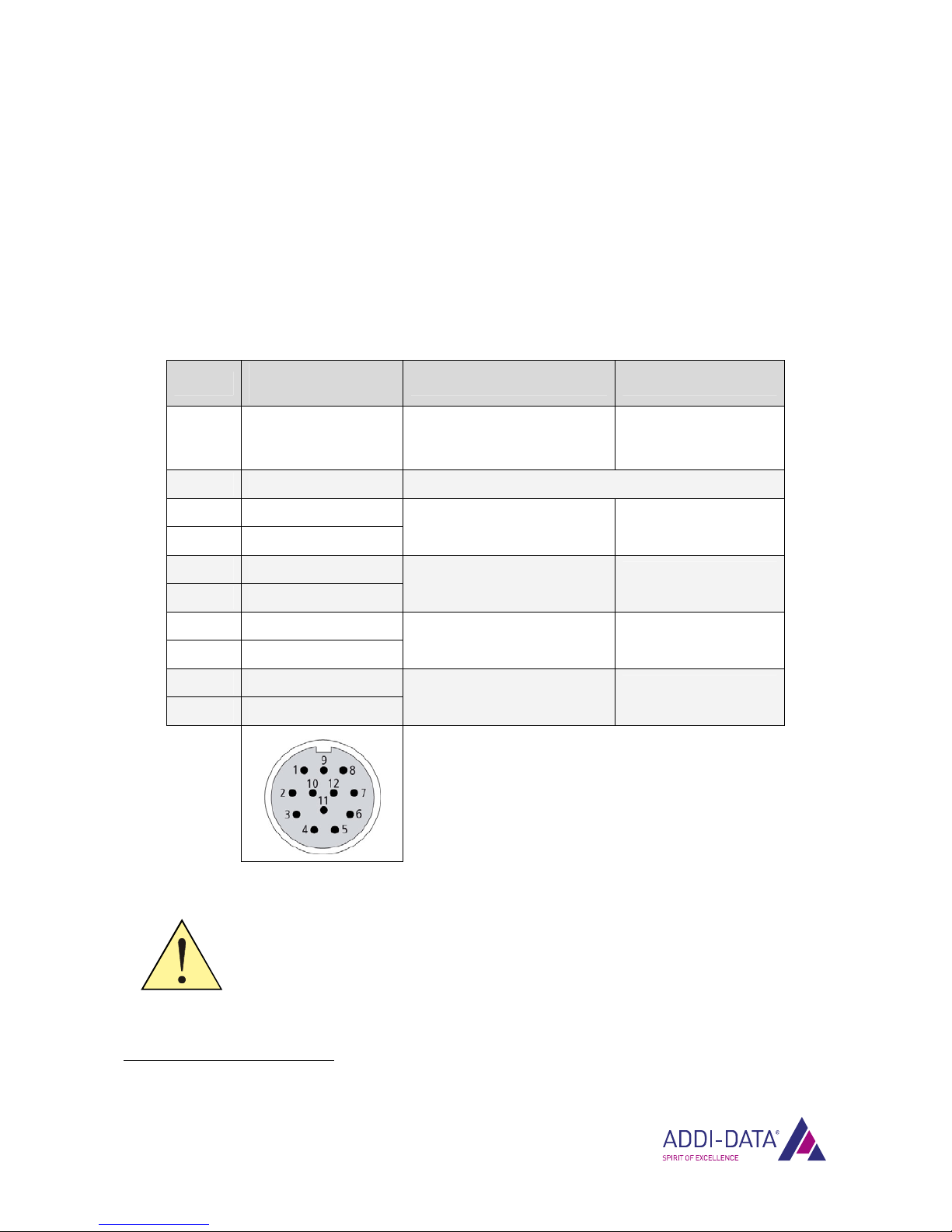
To each M23 female connector, one rotary encoder can be connected.
Table 3-1: Pin assignment: Incremental counter inputs
Pin No. Female connector,
12-pin, M23 Polarity Function
2, 12 Voltage supply
24 V or 5 V1
Output 5 V / 24 V
(can be set via jumper),
condition upon delivery: 5 V
Supply for
incremental encoder
10, 11 GND GND
5 A+
6 A-
Input RS422/TTL Trace A
Incremental signal
8 B+
1 B-
Input RS422/TTL Trace B
Incremental signal
3 C+
4 C-
Input RS422/TTL Trace C
Index
9 D+
7 D-
Input RS422/TTL Reference signal for
reference point logic
WARNING!
Sensors transmitting RS422 or TTL signals must not be connected to
the system MSX-E1701-24V (see Chapter 7.3).
1see Chapter 3.2
Function description: Incremental counter inputs MSX-E1701
www.addi-data.com 13
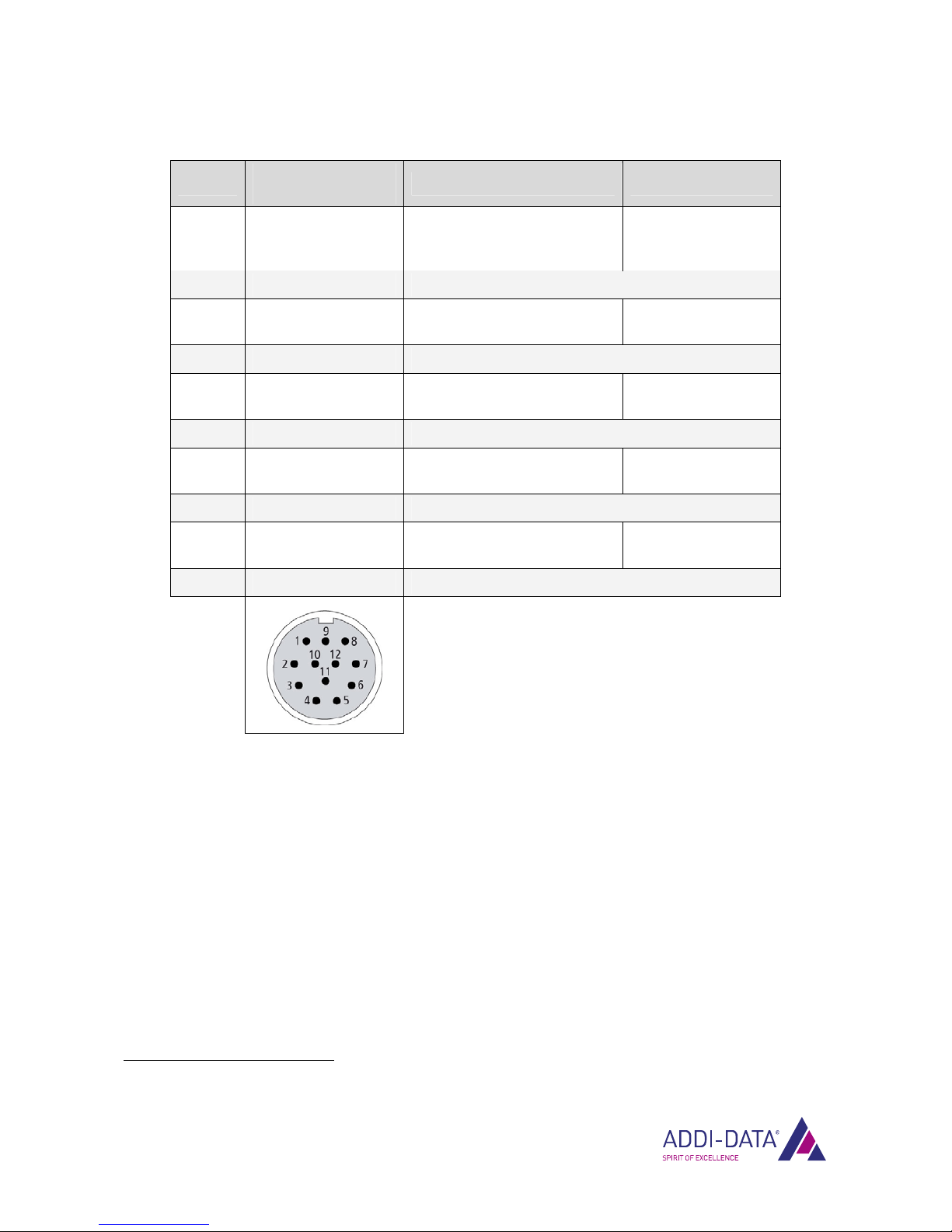
Table 3-2: Pin assignment: Incremental counter inputs (MSX-E1701-24V)
Pin No. Female connector,
12-pin, M23 Polarity Function
2, 12 Voltage supply
24 V or 5 V2
Output 5 V / 24 V
(can be set via jumper),
condition upon delivery: 24 V
Supply for
incremental encoder
10, 11 GND GND
5 A+ Input 24 V Trace A
Incremental signal
6 A- not connected
8 B+ Input 24 V Trace B
Incremental signal
1 B- not connected
3 C+ Input 24 V Trace C
Index
4 C- not connected
9 D+ Input 24 V
Reference signal for
reference point logic
7 D- not connected
2see Chapter 3.2

Function description: Incremental counter inputs MSX-E1701
3.2 Selecting the supply voltage
At pins 2 and 12 of the M23 female connector, you can select between a supply voltage of 24 V and
5 V. This voltage is set by means of a jumper.
The jumper is inside the housing of the MSX-E system. In order to set the jumper to the desired
position, the right-hand side of the housing (see Fig. 3-1) needs to be opened.
i IMPORTANT!
Please note the following:
•The housing of the MSX-E system may be opened only for this
purpose (see also Chapter 1.2.4)!
•Use safeguarding against electrostatic charge!
•The MSX-E system must not be connected to a voltage source during
work at the housing and the jumper!
•When the housing is opened, neither solid nor liquid foreign bodies
(dirt, moisture, etc.) may enter the inside of the housing!
Fig. 3-1: MSX-E1701: Right-hand side of the housing
Fig. 3-2: 24 V supply: Jumper at positions 1 and 2
www.addi-data.com 14
Function description: Incremental counter inputs MSX-E1701
Fig. 3-3: 5 V supply: Jumper at positions 2 and 3
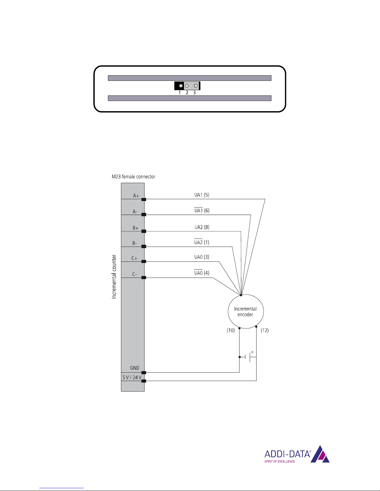
3.3 Connection example
Fig. 3-4: Connection example: Incremental encoder
www.addi-data.com 15

Function description: Incremental counter inputs MSX-E1701
3.4 TTL signal to RS422 input
i IMPORTANT!
This option does not apply to the system MSX-E1701-24V.
A TTL signal may also be connected to a differential RS422 input using a reference voltage of approx.
1.4 V. The reference voltage is switched on through software and output at pin D- of the M23 female
connector. On that condition, a differential signal cannot be connected to input D.
TTL signal to input D
The reference voltage is output at pin D-. The ground of the TTL signal must be connected to the
ground of the female connector. The TTL signal has to be connected to pin D+.
TTL signal to input A / B / C
The reference voltage needs to be connected externally from pin D- to the desired negative input
(A- / B- / C-). The ground of the TTL signal must be connected to the ground of the female connector.
The TTL signal has to be connected to the requested positive input (A+ / B+ / C+).
3.5 Acquisition modes
There are four modes available for the acquisition of incremental encoder signals.
Table 3-3: Incremental counter: Acquisition modes
Mode Feature
Single Acquisition with a quarter of the highest possible resolution
Double Acquisition with half of the highest possible resolution
Quadruple
Acquisition with the highest possible resolution
Direct Acquisition without detection of the direction
www.addi-data.com 16

Function description: Incremental counter inputs MSX-E1701
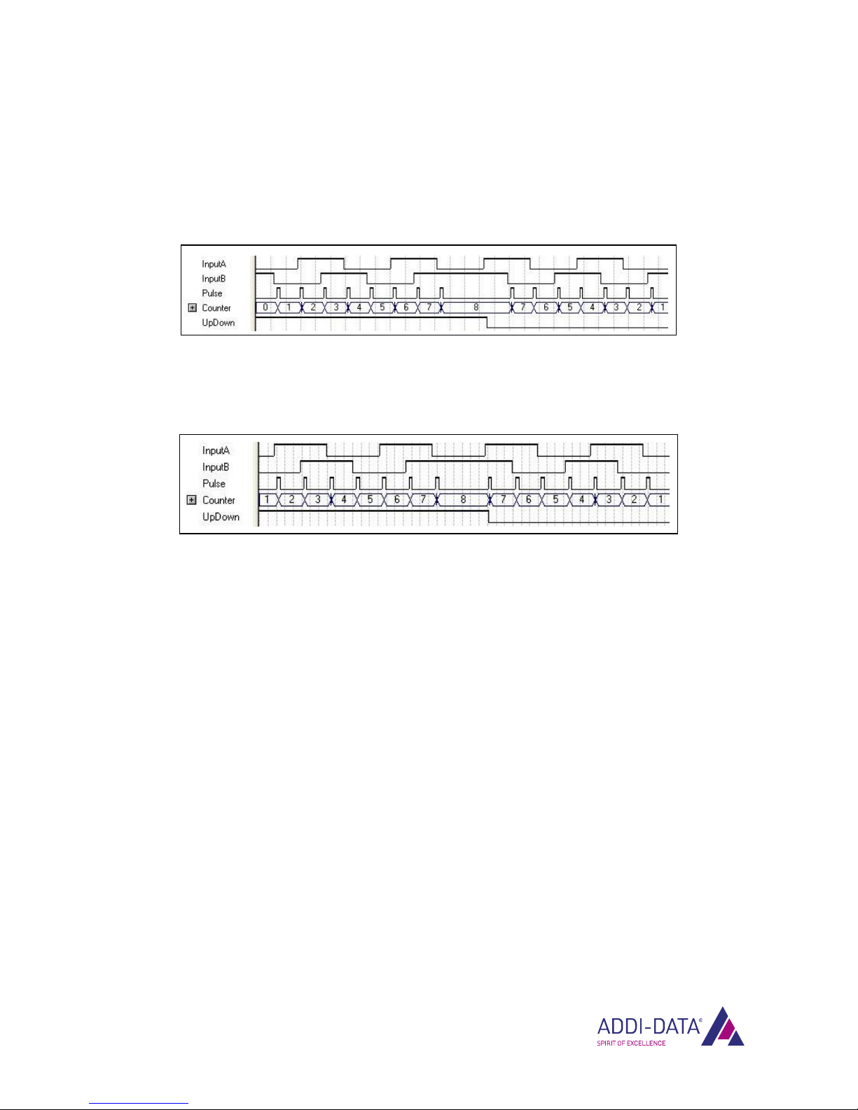
a) Single mode
In single mode, if trace A of the incremental encoder signal is on “high”, the system counts with each
rising edge of trace B.
Fig. 3-5: Incremental counter: Single mode
b) Double mode
In double mode, the system counts with each rising and falling edge of trace B.
Fig. 3-6: Incremental counter: Double mode
c) Quadruple mode
In quadruple mode, the system counts with each rising and falling edge of traces A and B.
Fig. 3-7: Incremental counter: Quadruple mode
d) Direct mode
In direct mode, the system counts with each falling edge of trace A, with input B serving as a gate
input. The system counts only if trace B is on “high”.
Moreover, in direct mode, the direction of counting can be programmed through software.
Fig. 3-8: Incremental counter: Direct mode
www.addi-data.com 17
Function description: Incremental counter inputs MSX-E1701
3.5.1 Options
1) Hysteresis function
The hysteresis function can be used in single, double and quadruple mode.
Fig. 3-9: Quadruple mode: Hysteresis “on”
With hysteresis “on”, the first counting pulse after a change of rotational direction is not evaluated.
Fig. 3-10: Quadruple mode: Hysteresis “off”
2) Way of counting
In direct mode, counting can be either upwards or downwards.
3.6 Frequency measurement
During frequency measurement, all pulses within a selected time frame are counted.
This interval may take 100 ns to 6.55 ms. Depending on the mode set (see Chapter 3.5), a pulse is
counted at a rising or falling edge of the incremental encoder signal.
The frequency measurement is started independently of the input signal through software. The 32-bit
counter is set to zero then. When the measurement is finished, the frequency of the input signal is
calculated from the length of the time frame and the number of counted pulses.
3.7 Compare logic
It is possible to use the compare logic for the generation of a trigger or synchro trigger signal in order
to latch the counter value.
There are two compare logic modes:
a) Simple mode
In Simple mode, a reference value can be indicated. As soon as the counter value corresponds to the
reference value, a trigger or synchro trigger is released.
www.addi-data.com 18

Function description: Incremental counter inputs MSX-E1701
b) Modulo mode
In Modulo mode, a reference value is indicated as well. When the counter value corresponds to the
reference value or a multiple of it, a trigger or synchro trigger is released.
3.8 Index and reference point logic
The index signal of an incremental encoder can be used either for latching or latching and deleting the
counter value.
You can select if the rising edge, the falling edge or both edges of the index signal should be counted.
Depending on the mode, the counter value is latched only once or endlessly after each defined edge.
Examples
a) Index logic with falling edge in continuous mode
In addition to the index logic, the reference point logic can be activated.
In this case, the defined edge of the index signal is counted only after a falling edge of the external
reference signal. Further relevant edges of the index signal are not taken into account until the next
falling edge of the reference signal has been counted.
b) Index logic with rising edge in continuous mode and reference point logic with falling edge
3.9 Hardware trigger
The digital 24 V trigger input of the MSX-E system can be used to latch the incremental counter value.
You can select if the rising edge, the falling edge or both edges of the trigger signal generated
externally should count. By means of the counter, you can define after which number of edges the
incremental counter value is to be latched.
Examples:
•Selected edge: rising
Counter value: 1
The incremental counter value is latched after every rising edge of the trigger signal.
•Selected edge: rising
Counter value: 3
The incremental counter value is latched after every third rising edge of the trigger signal.
•Selected edge: rising and falling
Counter value: 3
The incremental counter value is latched after every third edge of the trigger signal.
www.addi-data.com 19

Function description: Incremental counter inputs MSX-E1701
www.addi-data.com 20
In order to suppress interfering signals, a software-programmable digital filter can be used for the
trigger input.
The filter time may be in the range between 250 ns and 16.38 ms. When the filter is activated, every
positive or negative pulse lasting shorter than the defined filter time is suppressed.
3.10 Digital filter for the incremental counter inputs
Not only for the hardware trigger input, but also for the incremental counter inputs a programmable
digital filter can be used to eliminate interfering signals.
For each of the four inputs, the filter can be set individually. The filter time may be 100 ns to 26.2 ms.
When the filter is activated, every positive or negative pulse lasting shorter than the defined filter time
is suppressed.
Other manuals for MSX-E1701
3
Table of contents
Other Addi-Data Network Hardware manuals


Popular Network Hardware manuals by other brands

Altronix
Altronix TROVE T2AGK78 installation guide

technetix
technetix AIMA3000 Product user manual

Universal Devices
Universal Devices Z-Matter Assembly instructions

Digikeijs
Digikeijs DR5052 DIGITURN instruction manual
-Frt(prt) Product End-of-Life Disassembly Instructions")
HP
HP A5920AF-24XG Bk(pwr)-Frt(prt) Product End-of-Life Disassembly Instructions

Frontier
Frontier airi Air 4920 Quick install guide


SriHome
SriHome NVS007 Quick operation guide

Digiever
Digiever DS-4200-RM Pro Series Quick installation guide

Conrad
Conrad 41 35 11 operating instructions

Akytec
Akytec MV210-212 user guide

ATTO Technology
ATTO Technology FibreBridge 1190E Installation and operation manual

Motorola
Motorola DSR-4410MD Operator's guide