Additel 273E Series User manual

1
273Ex
Handheld Pressure Calibrator


ADT273Ex Handheld Pressure Calibrator
User Manual
[Version:2302V02]
Additel Corporation

STATEMENT
This user manual provides operating and safety instructions for the 273Ex Handheld Pressure
Calibrator. To ensure correct operation and safety, please follow the instructions in this manual.
Additel Corporation reserves the right to change the contents and other information contained in
this manual without notice.


I
Content
Safety instructions...............................................................................................................................................................1
Special safety requirements................................................................................................................................................2
Intended use .......................................................................................................................................................................5
1. Introduction .....................................................................................................................................................................6
1.1 Product Overview...................................................................................................................................................6
1.2 Technical specification ...........................................................................................................................................7
1.2.1 General specification ...................................................................................................................................7
1.2.2 Signal measure specification (environmental temp.: 20±10℃, 1 year accuracy ..........................................9
1.3 Basic Structure.....................................................................................................................................................10
1.4 Standard Package Contents ................................................................................................................................ 11
1.5 Power supply description .....................................................................................................................................13
2. Overview for display and basic functions ......................................................................................................................14
2.1 Main interface.......................................................................................................................................................14
2.1.1 Status bar...................................................................................................................................................14
2.1.2 Apps list......................................................................................................................................................15
2.1.3 Main function guide....................................................................................................................................15
2.2 Control center.......................................................................................................................................................16
2.2.1 Date and battery ........................................................................................................................................16
2.2.2 Diagnostic center and screenshot..............................................................................................................16
2.2.3 Shortcut settings ........................................................................................................................................17
3. Calibrator.......................................................................................................................................................................18
3.1 Electrical Measurement........................................................................................................................................19
3.1.1 Voltage measurement ................................................................................................................................19
3.1.2 Current measurement ................................................................................................................................19
3.1.3 Frequency measurement ...........................................................................................................................20

II
3.1.4 Pulse measurement ...................................................................................................................................20
3.1.5 Switch measurement .................................................................................................................................20
3.1.6 Filter...........................................................................................................................................................21
3.1.7 Scaling .......................................................................................................................................................22
3.2 HART Communications........................................................................................................................................23
3.2.1 Search and connection ..............................................................................................................................24
3.2.2 Setting........................................................................................................................................................25
3.2.3 Diagnosis and service................................................................................................................................26
3.2.4 Process variable setting.............................................................................................................................32
3.3 Pressure measurement........................................................................................................................................32
3.3.1 Filter...........................................................................................................................................................33
3.3.2 Module information ....................................................................................................................................33
4. System settings.............................................................................................................................................................34
4.1 Bluetooth communication.....................................................................................................................................34
4.2 Power management.............................................................................................................................................34
4.3 System calibration................................................................................................................................................34
4.4 Services ...............................................................................................................................................................35
4.4.1 Maintenance .............................................................................................................................................35
4.4.2 Restore to factory data............................................................................................................................35
4.4.3 Running information................................................................................................................................35
4.4.4 System upgrade .......................................................................................................................................35
4.5 Personalization.....................................................................................................................................................35
4.5.1 Sound ........................................................................................................................................................35
4.5.2 Language ..................................................................................................................................................36
4.5.3 Date & Time ..............................................................................................................................................36
4.6 Product information..............................................................................................................................................36
5. Data management.........................................................................................................................................................37
6. Quick test ......................................................................................................................................................................37
6.1 Dial pressure gauge and digital pressure gauge calibration.................................................................................38

III
6.2 Pressure transmitter (voltage, current and HART) ...............................................................................................39
6.3 Pressure switch....................................................................................................................................................40
7. Applications...................................................................................................................................................................42
7.1 Units converter.....................................................................................................................................................42
7.2 Leak test ..............................................................................................................................................................42
7.2.1 Leak Test Performing .................................................................................................................................42
7.3 PSV test ...............................................................................................................................................................43
7.3.1 PSV test performing...................................................................................................................................43
7.4 Pressure delta......................................................................................................................................................43
7.5 Wiring help ...........................................................................................................................................................45

IV
Figure Content
Figure 1 Basic Structure.............................................................................................................................................10
Figure 2 Adaptor and the power plug .........................................................................................................................13
Figure 3 Main interface ..............................................................................................................................................14
Figure 4 Control center ..............................................................................................................................................16
Figure 5 Calibrator main screen.................................................................................................................................18
Figure 6 Voltage/ frequency/ pulse/ switch Measurement..........................................................................................19
Figure 7 Current measurement ..................................................................................................................................19
Figure 8 Filter settings................................................................................................................................................21
Figure 9 Scaling configurations..................................................................................................................................23
Figure 10 Internal power + internal resistance ...........................................................................................................24
Figure 11 External power + external resistance .........................................................................................................24
Figure 12 Current loop test ........................................................................................................................................27
Figure 13 PVAO zero .................................................................................................................................................28
Figure 14 D/A adjustment...........................................................................................................................................29
Figure 15 Range migration.........................................................................................................................................30
Figure 16 Sensor trim.................................................................................................................................................31
Figure 17 Process variable selection .........................................................................................................................31

1
Safety instructions
Warning:
To prevent the user from injury, please follow this user manual for use.
To prevent possible fire, electric shock or personal injury, please do as follows:
Normal:
◆Please read the user manual before using the product, especially the Safety Instructions;
◆Please charge the battery when a low battery level is displayed in case of the measurement abnormal;
◆Do not expose the battery to fire or short circuit the battery;
◆Before using the product, please check the appearance of the product for any damage;
◆If the product is damaged or malfunctions, do not use it, and contact Additel;
◆Do not touch the metal part of the probes or test cables during use;
◆Please remove unnecessary probe, cable or other accessories before using the product;
◆Do not use damaged or worn cable.
Attention:
To prevent damage this product or the device under tested, please obey the instruction manual for use
◆Do not use the instrument in a high vibration environment;
◆Use only the Additel power adaptor and designated battery models;
◆In case of working with an external pressure module, refer to the Safety instructions of its manual.

2
Special safety requirements
1. WARNING – DO NOT OPEN WHEN AN EXPLOSIVE ATMOSPHERE IS PRESENT
2. WARNING – DO NOT CHARGE THE BATTERY IN HAZARDOUS LOCATION
3. WARNING – USE ONLY the approved batteries
4. The equipment needs to protected from impacts with high impact energy
5. Do not touch the non-metallic enclosure or touch with the insulating materials only
6. The batteries used in the equipment with same manufacturer, same models and same electrochemical system
7. The conformal coating is applied to PCB boards was declared meet the requirements of IEC 60664-1 and IEC
60664-3 by manufacturer
8. Tamb: -20°C to +50°C.
9. USB port only to be used in Non-hazardous area.
10. PX connect with pressure measuring module CDPX-Ex only; the connected cables and flexible hose used for the
external pressure modules are made of insulation materials, so end user should consider the risk of electrostatic
discharge during material selection and installation process
11. Metallic parts (only fasteners) presented a maximum capacitance of total 110pF, end user should consider this risk
for suitable application
12. No additional input energy limitation are required for Type-C USB port and DC charging port when Um does not
exceed 250V (internal OVP/OCP are designed in line with IEC 60079-11)
13. Do not remove the silicone rubber protective sleeve from the enclosure of equipment in Hazardous area
14. IS parameters must be strictly observed in full for different external measuring ports on the different models in
accordance with Ex instruction

3
15. Intrinsically safe electrical system between IS apparatus and Associated apparatus or other IS apparatus:
Item
I.S Interface
External Measuring Instrument
System
Equipment group
IIC
IIC
IIC
Level of protection
ia
ia
ia
Temperature class
T4
T4
T4
Ambient temperature
-20°C~+50°C
-20°C~+50°C
Voltage
Uo
Ui(30V)
Current
Io
Ii(100mA)
Power
Po
Pi(0.75W)
Cable parameters
Capacitance
Co
Ci
Cc
Inductance
Lo
Li
Lc
L/R ratio
/
/
/
Grounding
Isolated
Isolated
Isolated
Uo ≤Ui
Io ≤Ii
Po ≤Pi
Co ≥Ci+Cc
Lo ≥Li+Lc

4
Standard Compliance
•EN IEC 60079-0:2018
•EN 60079-11:2012
•IEC 60079-0:2017 Edition 7.0
•IEC 60079-11:2011 Edition 6.0
Ex information for equipment name
•National regulations: ATEX directive 2014/34/EU and IECEx scheme 02
•Certificate No.: TÜV 20 ATEX 8509 X and IECEx TUR 20.0009X
•Ex Marking for EU-Type Examination: II 1 G Ex ia IIC T4 Ga
•Ex Marking for IECEx CoC: Ex ia IIC T4 Ga
•Tamb: -20°C~+50°C
•IP Rating: IP20
•I.S Parameters:
Additel273Ex
Handheld Pressure Calibrator

5
Input parameters, simple connection
Connection
Function
Ui/V
Ii/mA
Pi/mW
Ci/nF
Li/mH
J1、J3
HART (external power and external
resistance)
30
100
750
10
0
J2、J3
Current measurement
30
100
750
1
0
J4、J3
Voltage, frequency and switch
measurement
30
100
750
1
0
J1、J2
Loop Circuit Transmitter Current
Measuring / HART(Internal Power and
Resistance)
30
100
750
10
0
Output parameters, simple connection
Connection
Function
Uo/V
Io/mA
Po/mW
Co/µF
Lo/mH
J1、J3
HART (external power and external
resistance)
25.2
79.16
499
0.107
9
J2、J3
Current measurement
5
0.85
1.1
87
100
J4、J3
Voltage, frequency and switch
measurement
5
0.85
1.1
87
100
J1、J2
Loop Circuit Transmitter Current
Measuring / HART(Internal Power and
Resistance)
25.2
79.16
499
0.107
9
Intended use
•The equipment to be used in Zone 0 hazardous area with gas group IIC.
•The equipment is used in oil and gas platforms, oil refineries, chemical and petrochemical plants,
pharmaceutical industry, energy and gas processing industries.

6
1. Introduction
1.1 Product Overview
Additel's 273Ex is an intrinsically safe handheld multifunctional pressure calibrator with a color touchscreen,
smartphone like interface, built-in quick test tasks and optional HART communications capability. This innovative Additel
product drastically improves explosion-proof field testing and calibration. The Additel 273Ex has a built-in atmospheric
pressure sensor, so that absolute pressure and the gauge pressure are easily facilitated. With three pressure module
inputs, one switchable at the bottom and two digital inputs on the side, the user can configure the setup accordingly and
easily meet the needs of pressure calibration and testing in virtually any environment.
Contact Us
TEL: 1-714-998-6899
Or visit Additel website: www.additel.com

7
1.2 Technical specification
1.2.1 General specification Table 1 General specification
General Specifications
Input Channels
Top: 1 electrical signal measurement channel, φ4mm banana jacks
Right side: 2 channels for external digital pressure modules, 5-core dedicated aviation plug
Bottom: embedded digital pressure module (model ADT158Ex), field switchable.
Internal: 1 embedded atmospheric pressure sensor
BarometricAccuracy
±55 Pa
Measurement Rate
mV, V, mA & frequency: 3 times/sec
Pressure module: 1~10 times/sec selectable (3 as default)
Barometer: 1 time/sec
Power
4000mAh, 14.4Wh explosion-proof intelligent lithium battery, charging time = 6~8 hours, battery
can be charged independently
Typical working time 100 hours (measurement mode)
Environmental
Guaranteed temperature range of technical specifications: (-10 ~ 50)°C
*Temperature coefficient: ±5 ppm FS/°C (-20 to -10)°C
Operating temperature: (-20 ~ 50)°C
Storage temperature: (-30 ~ 70)°C
Humidity: 0% to 95% RH, non-condensing
Altitude: 3000 meters

8
Warm-up Time
10 min to fully meet technical specifications
Port Protection Voltage
30V max
Explosion-proof Grade
ATEX & IECEX: Ex ia IIC T4 Ga (Ta = -20°Cto + 50°C)
CSA: Class I, Division 1, Group A,B,C and D,
T4 Class I, Zone 0, AEx ia IIC T4 Ga
Ta = -20°Cto + 50°C Ex ia IIC T4 Ga
UKCA-EX
CE Certification
TUV IEC61326, IEC61010
Rohs Compliance
Rohs II Directive 2011/65/EU, EN50581:2012
Protection Level
IP67, 1 meter drop test
Communication
Isolate USB-Type C (slave), Bluetooth
Display
4.4-inch color display capacitive screen, transflective, with LED backlight
Size
6.97" x 4.13" x 2.04" (177 mm x 105 mm x 52 mm) which doesn't include bottom ADT158Ex.
Weight
1.98 lb (0.9 kg)
Warranty Time
1 year

9
1.2.2 Signal measure specification (environmental temp.: 20±10℃, 1 year accuracy
Table 2 Signal measure specification
Specification
Range
Accuracy
Resolution
Note
Voltage Measurement
±300mV
0.015%RDG + 0.005%FS
1uV
Impedance:>100MΩ
±30V
0.015%RDG + 0.005%FS
0.1mV
Impedance:>1MΩ
Current Measurement
±30mA
0.015%RDG + 0.005%FS
0.1uA
Impedance: <40Ω
Frequency
Measurement
0.01~50000Hz (auto range)
0.005% RDG + 2 last digit
6-digit auto-resolution
Min threshold voltage:
2.5V
Units: Hz, kHz, MHz, CPM, CPH, s, ms, us
Switch On-Off
Measurement
Inspection voltage: (3 ~ 30)V
Response speed: < 10ms, supports wet and dry switch
Pulse Count
0 ~ 9999999, optional rising edge and
falling edge Min threshold voltage: 2.5V
Loop Power
20V ± 10%, max output impedance: 320Ω, max load current: 25mA
Note 1: When the environmental temperature is (-20~-10) °C, the temperature coefficient is:
(1) Measure of voltage, current:±5ppmFS/°C.
Note 2: Input characteristics:
(1) Voltage range:-300~300mV input impedance >100 MΩ;
(2) Voltage range:-30~30V input impedance >1MΩ;
(3) Current measure: input impedance <40Ω;
Note 3:Minimum threshold voltage for frequency and pulse measure:2.5V;
Note 4:The frequency measure supports following units: Hz, kHz, MHz, CPM, CPH,s, ms, μs;
Note 5:There are rising edge and falling edge trigger mode available for pulse measure.

10
1.3 Basic Structure
Figure 1 Basic Structure
Table of contents
Other Additel Test Equipment manuals

Additel
Additel 927 Operating instructions
Additel
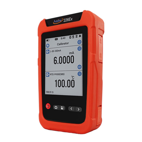
Additel 226Ex User manual
Additel
Additel 761A User manual
Additel
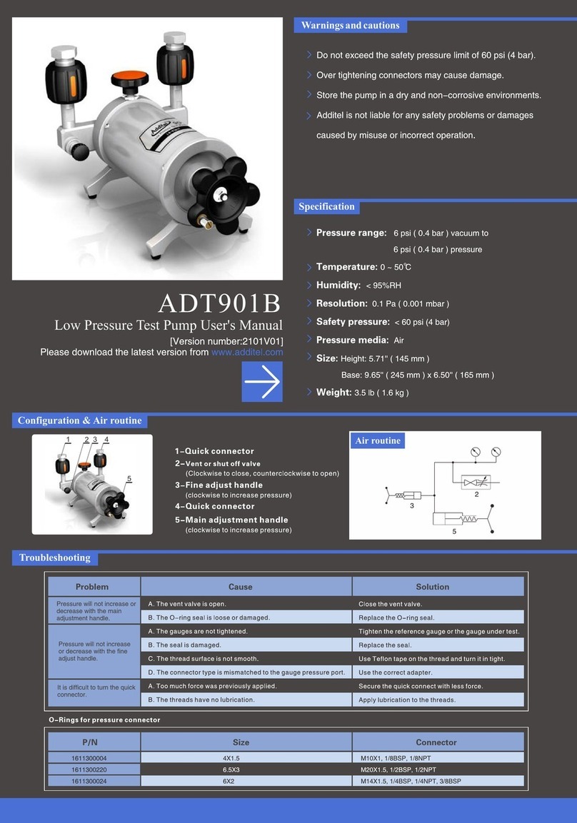
Additel ADT901B User manual
Additel
Additel 949 User manual

Additel
Additel 226 User manual

Additel
Additel ADT672 User manual

Additel
Additel 761A User manual

Additel
Additel ADT672 User manual
Additel
Additel ADT760 User manual
Additel
Additel 686 User manual
Additel
Additel ADT927 Technical specifications
Additel
Additel ADT286 User manual

Additel
Additel ADT760 User manual
Additel
Additel ADT209 User manual
Additel
Additel ADT761-D User manual

Additel
Additel ADT22 A Series User manual

Additel
Additel 226 User manual
Additel
Additel ADT761 Series User manual

Additel
Additel 762 User manual
