AddLife Ropox Toilet lifter Electric User manual
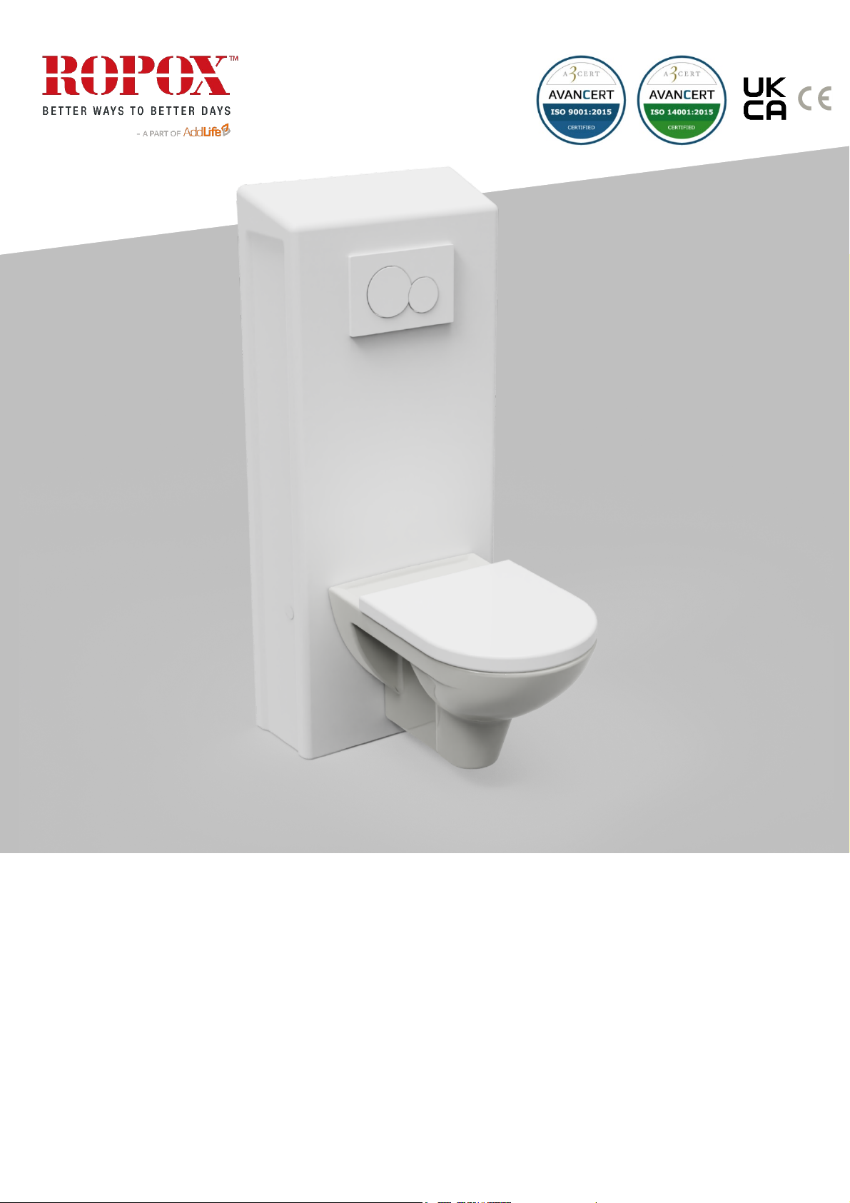
ROPOX Toilet lifter Electric
User manual
This manual should always be in close proximity of the
product
TF 200.11.0006 ENG / Date 03-05-2023

2
TF 200.11.0006_eng
Table of content
1. Symbols used in this manual ............................................................................................................. 4
2. General safety ..................................................................................................................................... 4
2.1 Product Unit label.................................................................................................................. 6
3. General requirements ......................................................................................................................... 7
3.1 Product information .................................................................................................................. 7
3.2 Product description .................................................................................................................. 8
3.3 Intended use ............................................................................................................................ 8
3.4 Intended operator..................................................................................................................... 8
3.5 Essential performance.............................................................................................................. 8
3.6 Non-clinical functions ............................................................................................................... 8
3.7 Clinical functions ...................................................................................................................... 8
3.8 Product dimensions.................................................................................................................. 8
4. Instructions for use............................................................................................................................. 9
4.1 Installation of product............................................................................................................ 9
4.1.1 Installation interface for water and electrical socket........................................................ 9
4.1.2 Installation interface for floor drain ............................................................................... 9
4.1.3 Installation interface for wall drain ...............................................................................10
4.1.4 Construction.................................................................................................................11
4.1.5 Mounting the product....................................................................................................12
4.1.6 Pair the Bluetooth remote.............................................................................................15
4.1.7 Unlock the handcontrol.................................................................................................15
4.1.5 … continued.................................................................................................................16
4.2 Operating the product ..........................................................................................................19
4.3 Residual risks ......................................................................................................................19
4.4 Installation of accessories ....................................................................................................20
4.4.1 Installation of height adjustable toilet support arms .......................................................20
4.4.2 Installation of backrest..................................................................................................23
4.4.3 Installation of bidet .......................................................................................................24
4.4.4 Mounting of fixed control in top of cover........................................................................24
4.4.5 Installation of extension cover.......................................................................................26
4.4.6 Increased crushing safety, accessory ...........................................................................27
5. Troubleshooting.................................................................................................................................28
6. Cleaning .............................................................................................................................................29
6.1 Preapproved disinfection products .......................................................................................29
6.2 Preapproved cleaning products [Toilet lifter] .........................................................................29
6.3 Preapproved cleaning products [Spiral cable] .......................................................................29
7. Maintenance.......................................................................................................................................30
7.1 Periodic maintenance...........................................................................................................30
7.2 Calibration of actuator ..........................................................................................................30
7.3 Maintenance of pipes and wiring ..........................................................................................30
8. Component parts list .........................................................................................................................31
9. Environmental protection..................................................................................................................31
10. Electromagnetic compatibility...........................................................................................................31

3
TF 200.11.0006_eng
10.1 Suitable Environments .....................................................................................................31
10.2 Adjacent and stacked use ................................................................................................31
10.3 Cables .............................................................................................................................31
10.4 RF portable equipment.....................................................................................................31
11. Accident reporting .............................................................................................................................32

4
TF 200.11.0006_eng
1. Symbols used in this manual
Warning!
Indication of potentially hazardous situation. If not avoided, it can result in serious injury or
death.
Caution!
Indication of potentially hazardous situation which may result in minor or moderate injury.
It may also be used to alert against unsafe practices.
Notification!
This symbol is used to notify correct use and handling of the product.
2. General safety
This manual must be read and understood before use and
installation. Always keep this manual in close proximity of the
product.
The use, installation and service of this product must be in
compliance with this manual to avoid accidents and serious
personal injury.
Never use or handle this product in other ways specified in
this manual as it can result in personal safety hazards and/or
cause damage to the product.
Persons installing and/or using this product either as operator
or user should have the necessary safety information and
access to this manual.
If the supply cord is damaged, it must be replaced by the
manufacturer, its service agent or similarly qualified
designated persons in order to avoid a hazard.

5
TF 200.11.0006_eng
Do not perform repairs, disassembly or assembly operations,
add-ons, re-adjustments or modification of the product
beyond what is described in this manual. These must be
carried out by Ropox or Ropox authorized personnel. Do not
perform service while in use.
This appliance can be used by children aged from 8 years
and above and persons with reduced physical, sensory or
mental capabilities or lack of experience and knowledge if
they have been given supervision or instruction concerning
use of the appliance in a safe way and understand the
hazards involved. Children shall not play with the appliance.
Cleaning and user maintenance shall not be made by
children.
Do not use the product if it has defects or have become
damaged before being repaired or replaced.
If the control box makes unusual noise or smells, switch off
the mains voltage immediately.
Take care that the cables are not damaged.
Unplug the mains cable on mobile equipment before it is
moved.
The products must only be used in an environment that
corresponds to their IP protection.
The information in this manual is based on correct installation
in accordance with installation instructions for this product.
Ropox cannot be held liable if the product is used in any way
that differs from stated in this manual and/or installation
instruction.
Ropox reserve the right to amend this manual and reference
documents without prior notice.
6
TF 200.11.0006_eng
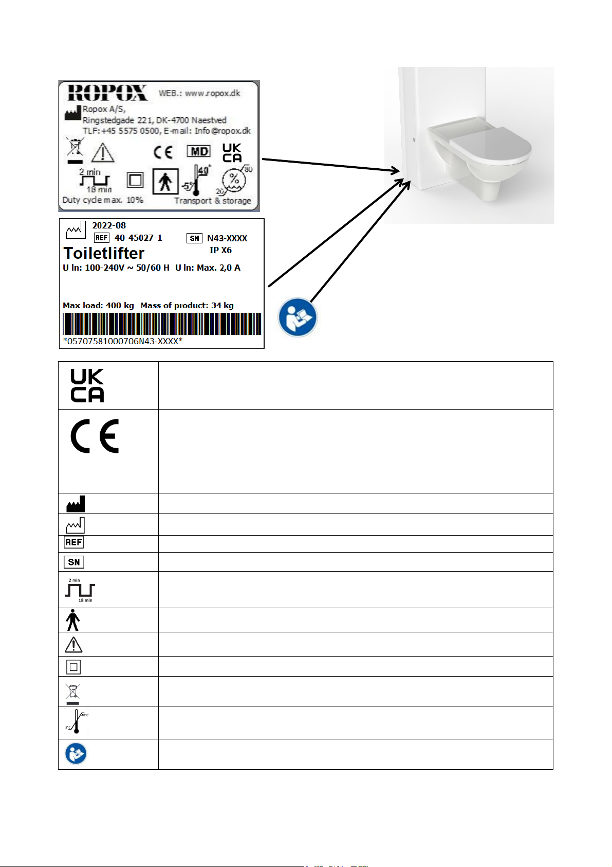
2.1 Product Unit label
This product is UKCA-marked in accordance with:
UK SI 2002 No. 618 - The Medical Devices Regulations 2002, and its amendments
This product is CE-marked in accordance with:
European Medical Device Regulation (EU)2017/745
Council Directive 2006/42/EC on machinery
Council Directive 2011/65/EU, RoHS
Manufacturer name and address
Date of production
Stock number
Serial number
Operating interval of electrically operated equipment. The use of electrical height
adjustable equipment can run at maximum 2 minutes, followed by an 18-minute
break.
Type B applied part. The product complies with IEC 60601-1 requirements to
provide protection against electric shock.
Consult manual for important safety related information, warnings, and safety
precautions.
Class II, double isolated electrical components.
Do not dispose as unsorted municipal waste. Product must be returned to a
designated recycling station.
Operating and storing temperatures may not exceed 5-40°C
Consult the instructions for use
Toilet Lifter Electric
Height adjustment 40-65 cm

7
TF 200.11.0006_eng
3. General requirements
3.1 Product information
Manufacturer
Ropox A/S
Ringstedgade 221, DK-4700 Naestved
+45 55 75 05 00
Email: Info@ropox.com
Product models
Part number
Model
Configuration
40-45027
40-46027
Toilet lifter Electric
Toilet lifter Electric
Floor drain
Wall drain
Expected service life
5 years
MDR Class
2017/745
Class I
Applied part
classification
60601-1
Type B applied part
MEE Class 60601-1
Class II
Intended environments
This product is to be used only in:
Professional Healthcare Environment
Homecare Environment
The device is not intended for use in special environments as defined by IEC 60601-1-2
Maximum user weight
according to ISO
17966:2016
400kg
Power supply
100-240V ~50/60Hz
I in
Max 2.0A
Intermittence
2min use / 18min pause
Height adjustment
400-650mm
Speed of actuation
≈8mm/s
IP rating
IPX6
Ambient temperature
range
-10 °C to +50 °C Transport and storage
+5 °C to +40 °C Operation
Relative humidity:
20% to 80% - non-condensing
Materials in contact with
patient
Components
Covers
Material description
ABS/PMMA plastic
Accessories
Item nr.
40-45011
40-45012
40-45013
40-45014
40-45015
40-45016
40-45018
40-45008
40-45100
40-45101
40-44070
40-44071
40-44074
40-44075
40-44276
40-45070
40-45071
40-45072
40-45073
Model
Height adjustable toiletsupports, Short straight
Height adjustable toiletsupports, Long straight
Height adjustable toiletsupports, Short Wave
Height adjustable toiletsupports, Long Wave
Height adjustable toiletsupports, Bariatric Short straight
Height adjustable toiletsupports, Bariatric Long straight
Height adjustable toiletsupports, Bariatric Long wave
Clamps, for height adjustment without tools
Backrest long (70cm Toilet)
Backrest short (56cm Toilet)
Wall hung toilet, 56cm
Wall hung toilet, 70cm
Toilet seat w/o lid
Toilet seat w/ lid
Svancare Bidet Elegant
Fixed Control button
Cover extension 30mm
Cover extension 60mm
Increased crushing safety
8
TF 200.11.0006_eng
3.2 Product description
The ROPOX toilet lifter electric can be set in heights ranging from 400-650mm by the use of the wireless
handset. Height adjustment will meet different sitting height needs various patient heights.
3.3 Intended use
The ROPOX height adjustable toilet lifter is intended to be used in both homecare and professional
healthcare environments. Adjusting the height will meet ergonomic demands emerging from various patient
heights.
The toilet lifter is not intended for playing, or as a training device.
The ROPOX Toilet Lifter gives people with reduced mobility the possibility to extend their independence. It
lowers and lifts the user to the best seated or standing position. Importantly it is straight-forward to set to the
optimum height for both user and helper. It is a solution using modern welfare technology to help users
become more self-reliant in their bathroom routines. The Toilet Lifter is an assistive aid which can support
users to keep their privacy for as long as possible. The height adjustment has an adjustment range of 25 cm
going from 40-65 cm.
3.4 Intended operator
The intended operator may include all that have read and understood this manual exempt kids.
3.5 Essential performance
The device does not have any function related to basic safety or essential performance. In case of loss or
degradation of performance, the user can get off the toilet.
3.6 Non-clinical functions
Height adjusting offers better ergonomics to user and caretaker.
3.7 Clinical functions
This product does not offer clinical benefits for patients, when used as intended by the manufacturer.
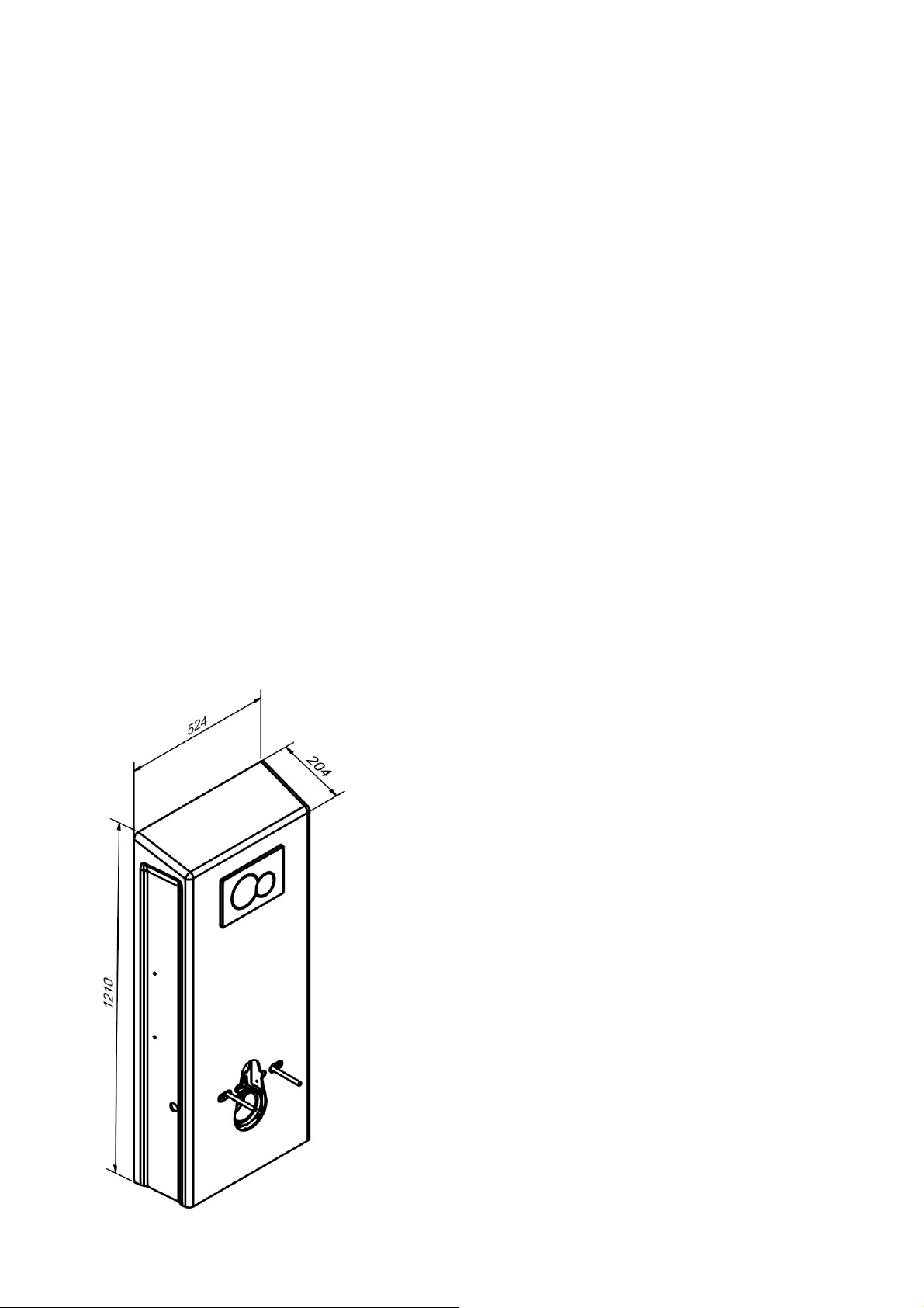
3.8 Product dimensions

9
TF 200.11.0006_eng
4. Instructions for use
4.1 Installation of product
The following instructions describe how to assemble and mount the toilet lifter, as well as optimal placement
of water, electrical and drain, based on whether the toilet lifter with floor drain or wall drain has been
purchased.
4.1.1 Installation interface for water and electrical socket
It is recommended to always place the water and electrical connections as shown below. In case of
deviations, it’s recommended to place the water and electrical sockets within the hatched areas.
4.1.2 Installation interface for floor drain
For 40-45027
For the toilet lifter with a floor drain, it’s recommended to place the drain within the hatched area, not
deviating further than the shown tolerances. This ensures the best flushing. The drain can be raised up to
40mm, so as to live up to Säker Vatten.
or raised up to 40mm
NB! All dimensions in mm
10
TF 200.11.0006_eng
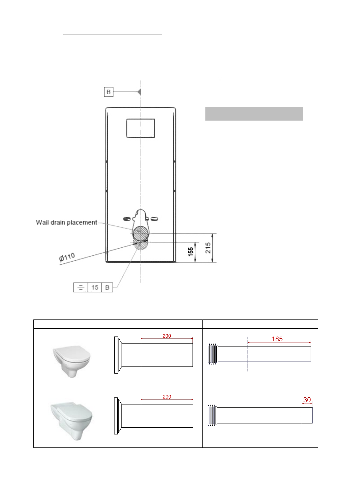
4.1.3 Installation interface for wall drain
For 40-46027
For the toilet lifter with a wall drain, it’s recommended to place the drain within the hatched area, not
deviating further than the shown tolerances. This ensures the best flushing.
Ropox supplied toilets
Shortening of ferrule
Shortening of flush pipe
40-44070
40-44071
NB! All dimensions in mm

11
TF 200.11.0006_eng
4.1.4 Construction
Note!
The toilet lifter is supplied with a set of 6 screws and rawlplugs suitable for mounting in a
concrete wall. The fitter should always consider the material, condition, and strength of the wall
and use screws and rawlplugs suitable for the specific wall type.
Caution!
Maximum pulling force per screw is 44kg, at 400kg max user weight according to ISO 17966:
2016
12
TF 200.11.0006_eng
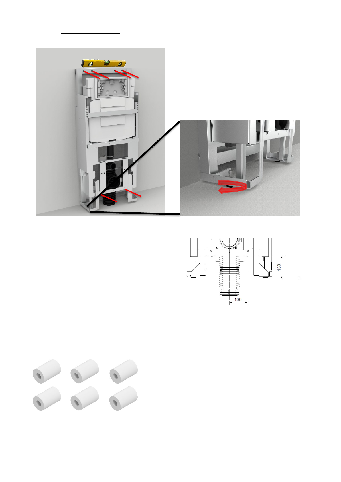
4.1.5 Mounting the product
a. Line up frame with adjustment screws. Mark out 6
holes and drill holes for appropriate rawlplugs. Ensure
that the center of the bottom 2 holes is at least
130mm above the floor
b. Connect water hose on wall outlet and electric
outlet before securing frame to the wall
c. Secure frame to wall. If the extension cover has been purchased, use the supplied distance bushings
to push out the frame from the wall. Longer screws have been supplied
13
TF 200.11.0006_eng
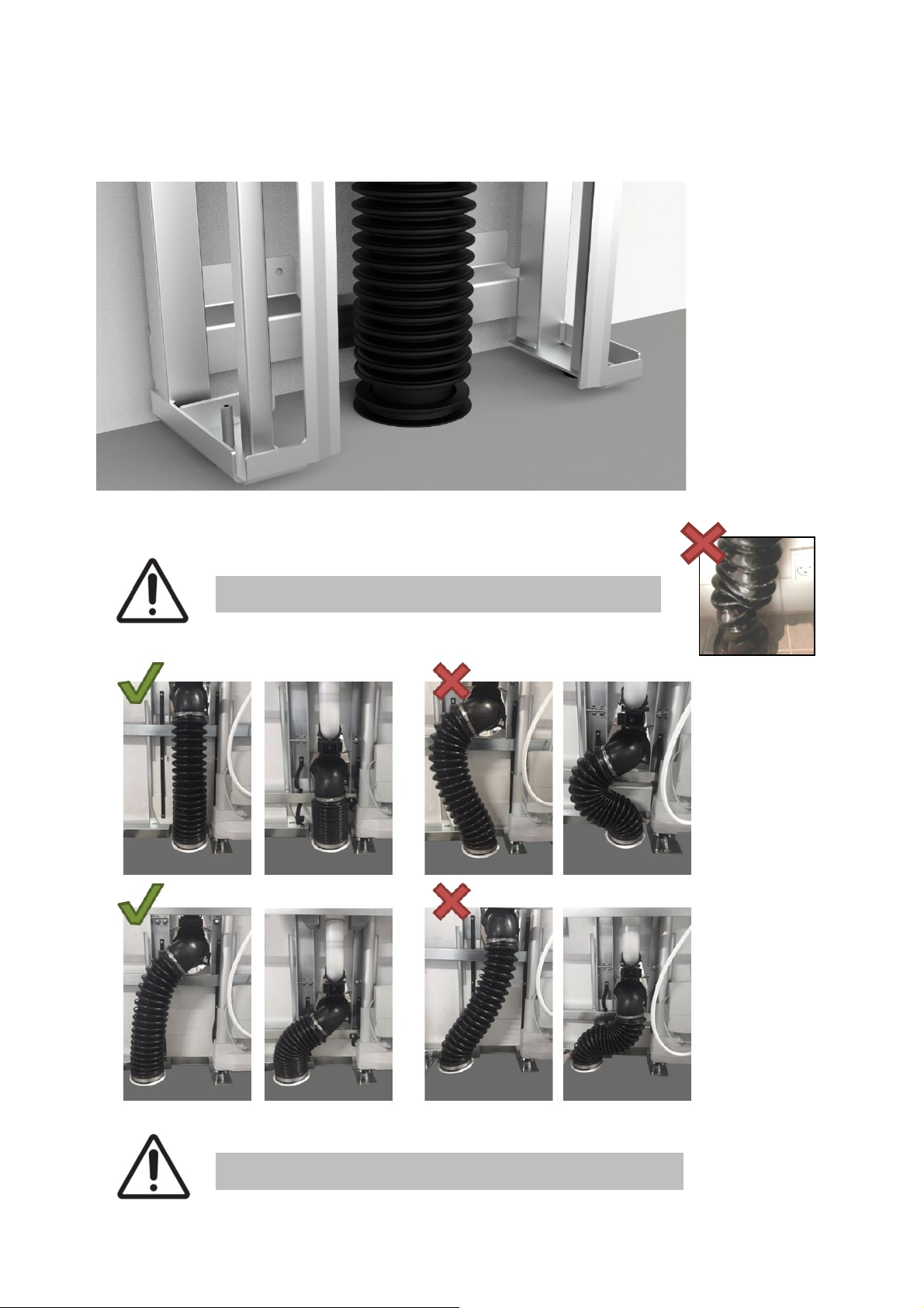
d1.
For 40-45027
If drain is in floor, mount the drain bellow as instructed below. The examples given below to the left, are
configurations that will work, but as a general rule, the installation interface in 4.1.2 should be followed.
Make sure the bellow is not twisted
Mount the bellow as shown below for correct flow

14
TF 200.11.0006_eng
d2.
For 40-46027
If drain is in wall, mount the drain bellow in wall drain, mount the accompanying brackets on the wall, so
that the toilet flange is held in place
Make sure the bellow is not twisted

15
TF 200.11.0006_eng
4.1.6 Pair the Bluetooth remote
Before continuing to mount the toilet lifter, it’s important to test the functionality of its travel. This is done by
pressing up or down on the remote control, then drive the full stroke. If the toilet lifter doesn’t react, it
means that the control must be paired to the lifter. This is done by following the steps listed below.
4.1.7 Unlock the handcontrol
The handcontrol will be unlocked when it is delivered, however, it’s possible to lock it accidentally,
preventing you from driving the lifter. This can occur due to repeated attempts of pairing. To unlock the
handcontrol, follow the listed procedure:
Note!
When pairing is complete, test product travel. Make sure all cables, water connection and
drain connection travel freely. The electrical connection shall travel unhindered and may
not get entangled in other installations.
Note!
If the control doesn’t drive after pairing, it means it needs to be unlocked. See 4.1.7!
1.
Stand within 2 meters of the toilet lifter, take the
hand control, and face it away from the lifter
2.
Hold the magnet key over its symbol, then hold
down the “Down” button (at least 3 seconds), until
the LED starts blinking
3.
Release the “Down” button, remove the magnet
key from the hand control, and move closer to the
toilet lifter, until the buzzer increases in frequency
4.
Press the “Down” button once. There should be
two beeps, this confirms pairing
1.
Take the handcontrol, then hold the magnet key
over its symbol
2.
While the magnet key is in this position, press the
”Down” button, then the ”Up” button
3.
If this doesn’t solve it, follow the pairing
procedure. Otherwise, it might not work due to
low battery, or if the lifter is unplugged from the
power

16
TF 200.11.0006_eng
4.1.5 … continued
e. Cut threaded rods to length and secure them in the frame
f. Mount inner cover 1 and 2
2x

17
TF 200.11.0006_eng
Before mounting inner cover 2, if the extension covers have been purchased, these must be mounted
beforehand. See 4.4.5
g. Mount outer cover (if the version with fixed control in the top of the cover is being installed, please
jump to section 4.4.4 – mounting of fixed control in top of cover)
If the extension covers have been purchased, these must be mounted before the outer cover. See 4.4.5
2x

18
TF 200.11.0006_eng
h.
Shorten ferrule and flush pipe to length and mount them.
i.
Mount the toilet and press pad.
j. Finish the installation by checking the following:
1. Rigidity test, sit on the toilet and check screw connections are firm.
2. Check that full travel of the product goes unhindered.
3. Check flushing and leaks.
19
TF 200.11.0006_eng
4.2 Operating the product
Operating the product is done by using the remote.
Warning!
The product should always be able to travel the full range of actuation without colliding with
objects. Failing to do so will compromise the product stability.
Special care should be taken in ensuring that no children or adults are sited under the
product as severe injury from entrapment may occur.
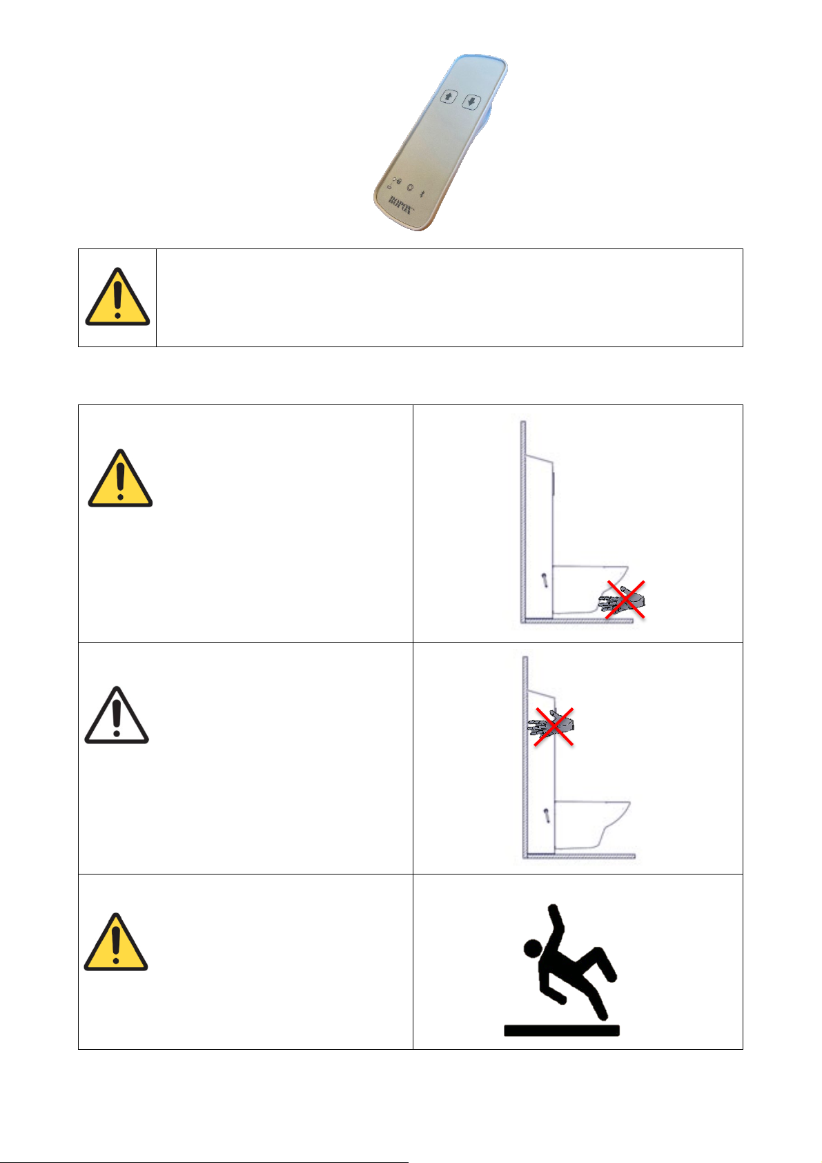
4.3 Residual risks
Warning!
Be aware that there may be no person or body parts
under the toilet when it is driven down, as it is a
crushing hazard.
Caution!
Do not place your hand/fingers between the wall
and the movable cover, as you risk crushing your
hand/fingers.
Warning!
In case of incorrect installation of plumbing parts,
water leaks can occur on the floor, which may
increase the risk of falling.
20
TF 200.11.0006_eng
4.4 Installation of accessories
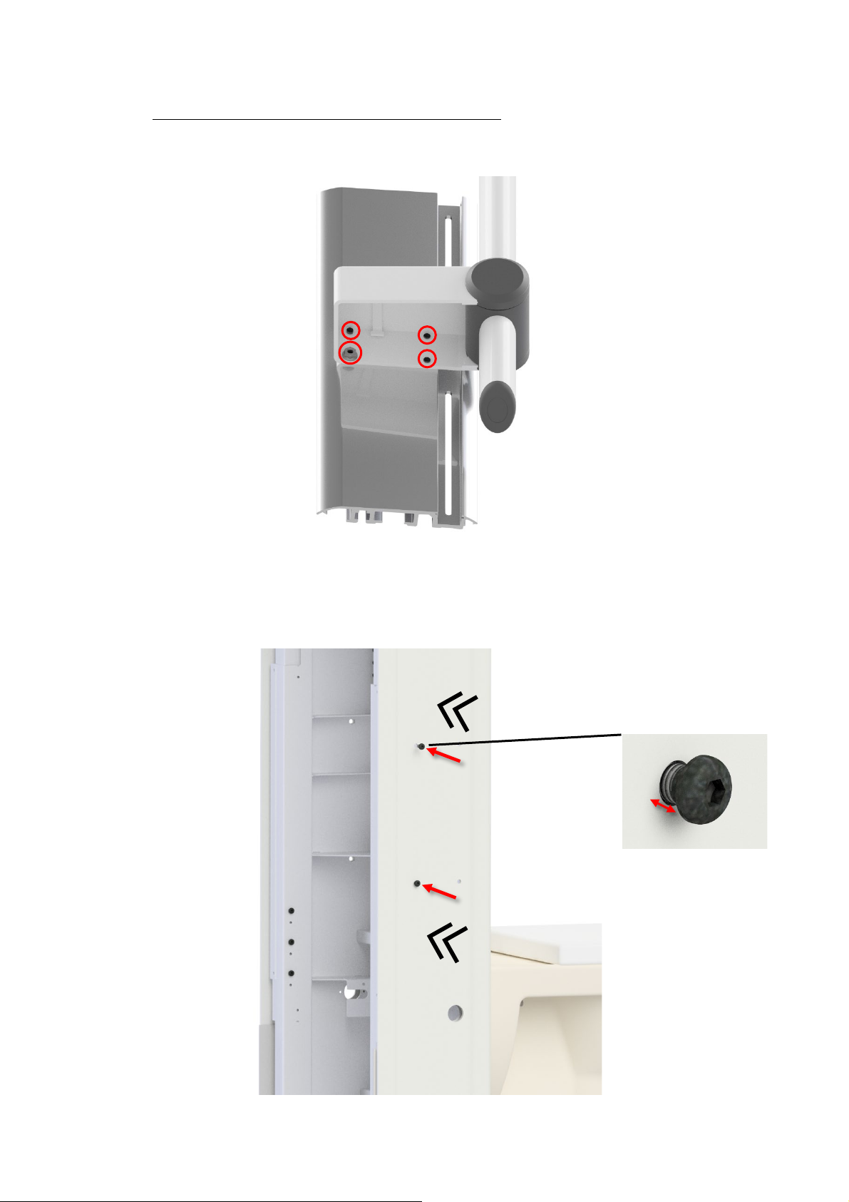
4.4.1 Installation of height adjustable toilet support arms
a. Attach housing to the profile with 3x M6x12 and 1x M6x16. Use a locking nut on M6x16.
b. Make sure that the plastic cover is pressed as far onto the frame as possible.
Mount 2x M6 buttonhead screws in the back holes on both sides.
Leave 5mm of clearance between underside of screw head to the plastic cover.
5 mm
This manual suits for next models
4
Table of contents
Other AddLife Bathroom Aid manuals


Popular Bathroom Aid manuals by other brands

Cobi Rehab
Cobi Rehab XXL-Rehab Rise N Tilt user manual

Invacare
Invacare 9630E Styxo Assembly, installation and operating instructions

Leckey
Leckey firefly splashy BIG user manual

NRS Healthcare
NRS Healthcare H85350 User instructions

Pressalit Care
Pressalit Care R2040 Assembly instruction

WENKO
WENKO 23285100 Assembly instructions


