Addvalue Innovation SABRE RANGER 5000 User manual

Version
:
1.0 (draft)
Date
:
11 Sep 2017
SABRE™RANGER 5000

SABRE™RANGER 5000 User Guide
© 2017 Addvalue Innovation Pte Ltd. All rights reserved. 2
Contents
Copyright ............................................................................................................................................................3
Warranty.............................................................................................................................................................3
Trademarks ........................................................................................................................................................3
Regulatory Information .......................................................................................................................................3
1. Introduction.....................................................................................................................................................6
2. Quick Reference.............................................................................................................................................7
3. Install the Sim Card ........................................................................................................................................8
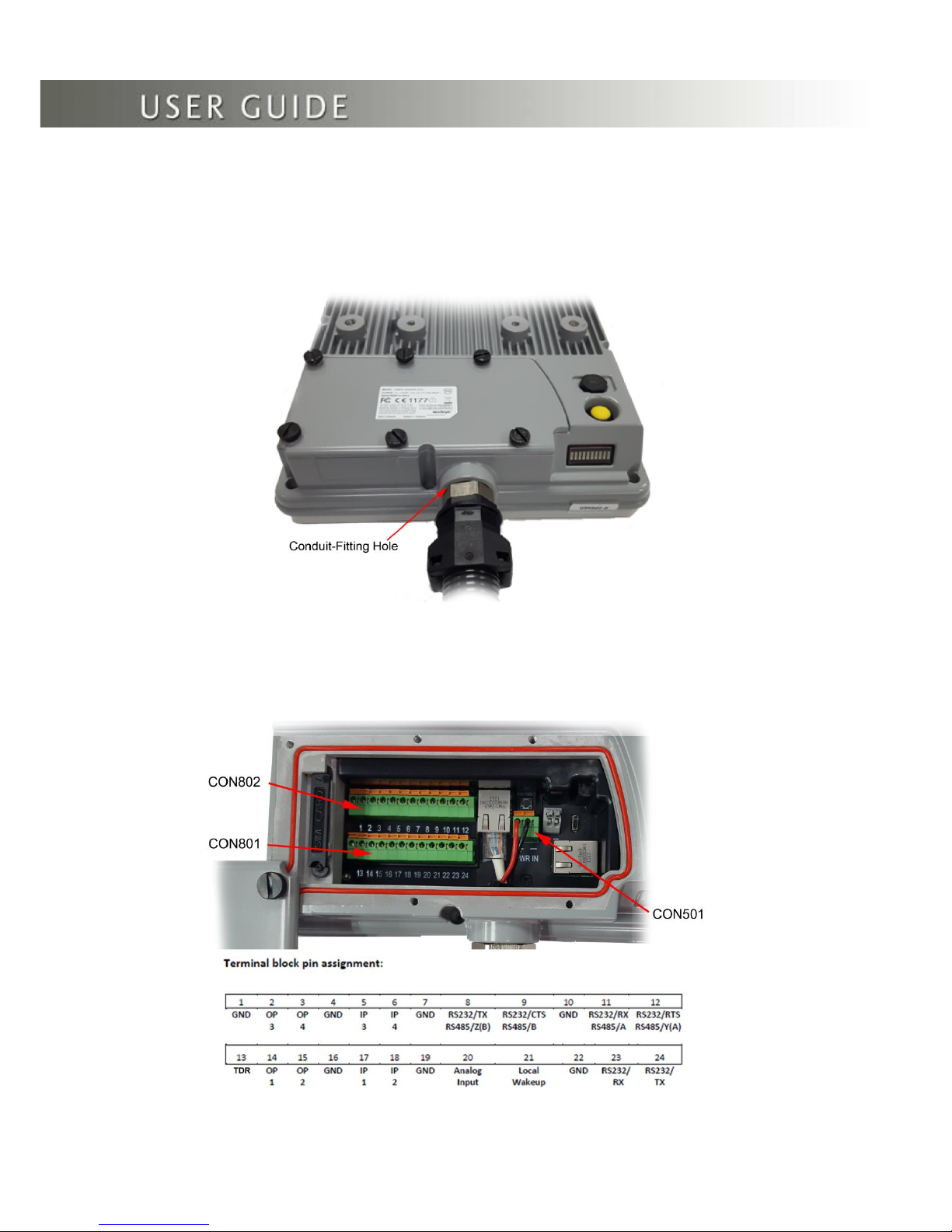
4. Connect the Cables and Wires.....................................................................................................................10
5. Optional Accessories....................................................................................................................................18
6. Fix Optional Mounting Bracket to Sabre™ Ranger 5000 .............................................................................19
7. Mount the Terminal on a Pole ......................................................................................................................20
8. Terminal Grounding......................................................................................................................................22
9. Point the Antenna.........................................................................................................................................23
10. Navigate to the Web Console.....................................................................................................................25
11. Web Console..............................................................................................................................................29
11.1 Data..........................................................................................................................................................31
11.1.1 Data Profile............................................................................................................................................31
11.1.2 Firewall ..................................................................................................................................................32
11.1.3 Port Forwarding.....................................................................................................................................35
11.1.4 Data Settings.........................................................................................................................................36
11.2 SMS..........................................................................................................................................................37
11.2.1 Compose ...............................................................................................................................................37
11.2.2 Inbox......................................................................................................................................................38
11.2.3 Sent .......................................................................................................................................................39
11.2.4 Draft.......................................................................................................................................................39
11.3 Settings.....................................................................................................................................................40
11.3.1 Accounts................................................................................................................................................40
11.3.2 Ethernet.................................................................................................................................................41
11.3.3 Security..................................................................................................................................................42
11.3.4 Terminal Settings...................................................................................................................................43
11.3.4.1 Reboot Terminal.................................................................................................................................43
11.3.4.2 Factory Reset .....................................................................................................................................43
11.3.4.3 Firmware Upgrade..............................................................................................................................44
11.3.4.4 Remote Access ..................................................................................................................................45
11.3.4.4 Power Saving .....................................................................................................................................46
11.3.4.5 Ciphering ............................................................................................................................................47
11.3.4.6 Facility Lock........................................................................................................................................47
11.3.4.7 IP Watchdog.......................................................................................................................................48
11.3.4.8 I/O Configurations...............................................................................................................................49
11.3.4.9 Backup/Restore..................................................................................................................................53
11.3.4.10 Web..................................................................................................................................................54
11.3.4.11 Antenna Pointing Buzzer..................................................................................................................54
11.3.4.12 GNSS Selection................................................................................................................................55
11.3.5 Terminal Info..........................................................................................................................................56
11.3.6 SMS Configurations...............................................................................................................................57
11.3.7 Language...............................................................................................................................................57
11.3.8 Support..................................................................................................................................................57
11.3.9 About .....................................................................................................................................................57
12. Web Console in Safe Mode........................................................................................................................58
13. Appendix A: Terminal Block Pin Assignment............................................................................................60
14. Appendix B: Conduit & Accessories..........................................................................................................62
15. Appendix C: Technical Summary..............................................................................................................63
16. Appendix D: Backup Configuration Reference Table.................................................................................65

SABRE™RANGER 5000 User Guide
© 2017 Addvalue Innovation Pte Ltd. All rights reserved. 3
Copyright
© Copyright 2017 Addvalue Innovation Pte Ltd
All rights reserved. This publication and its contents are proprietary to Addvalue Innovation Pte Ltd.
No part of this publication may be reproduced in any form or by any means without the written
permission of Addvalue Innovation Pte Ltd., 8 Tai Seng Link, Level 5 (Wing 2) Singapore 534158.
Warranty
Addvalue Innovation Pte Ltd has made every effort to ensure the correctness and completeness of
the material in this document. Addvalue Innovation Pte Ltd shall not be liable for errors contained
herein. The information in this document is subject to change without notice. Addvalue Innovation
Pte Ltd makes no warranty of any kind with regard to this material, including, but not limited to, the
implied warranties of merchantability and fitness for a particular purpose.
Trademarks
All trademarks, marks, names, or product names referenced in this publication are the property of
their respective owners. Addvalue Innovation Pte Ltd neither endorses nor otherwise sponsors any
such products or services referred to herein. SABRE™ RANGER 5000 is a trademark of Addvalue
Innovation Pte Ltd.
Microsoft, Windows, Windows NT, Windows 2000, Windows XP, and Windows 7 are registered
trademarks of Microsoft Corporation in the U.S.A. and/or other countries.
INMARSAT is a trademark of the International Mobile Satellite Organization. The Inmarsat LOGO
and the trademark BGAN are trademarks of Inmarsat (IP) Company Limited. All trademarks are
licensed to Inmarsat Limited.
All other company and product names may be the registered trademarks or trademarks of their
respective owners.
Regulatory Information
FEDERAL COMMUNICATION COMMISSION NOTICE
FCC Identifier: XXX-XXXXXXXX
USE CONDITIONS:
This device complies with part 15 of the FCC Rules. Operation is subject to the following two
conditions:
1. This device may not cause harmful interference, and
2. This device must accept any interference received, including interference that may cause
undesired operation.

SABRE™RANGER 5000 User Guide
© 2017 Addvalue Innovation Pte Ltd. All rights reserved. 4
NOTE:
This equipment has been tested and found to comply with the limits for a Class B digital device,
pursuant to Part 15 of the FCC Rules. These limits are designed to provide reasonable protection
against harmful interference in a residential installation. This equipment generates uses and can
radiate radio frequency energy and, if not installed and used in accordance with the instructions,
may cause harmful interference to radio communications. However, there is no guarantee that
interference will not occur in a particular installation.
If this equipment does cause harmful interference to radio or television reception, which can be
determined by turning the equipment off and on, the user is encouraged to try to correct the
interference by one of the following measures:
Reorient or relocate the receiving antenna.
Increase the separation between the equipment and receiver.
Connect the equipment into an outlet on a circuit different from that to which the receiver is
connected.
Consult the dealer or an experienced radio/TV technician for help.
IMPORTANT NOTE: EXPOSURE TO RADIO FREQUENCY RADIATION
This Device complies with FCC & IC radiation exposure limits set forth for an uncontrolled
environment. The Antenna used for this transmitter must be installed to provide a separation
distance of at least 100cm from all persons and must not be co-located or operating in conjunction
with any other antenna or transmitter.
FCC CAUTION:
Any Changes or modifications not expressly approved by the manufacturer could void the user’s
authority, which is granted by FCC to operate this satellite terminal, SABRE™ RANGER 5000.
INDUSTRY CANADA STATEMENT
ICC Identifier: XXXXX-XXXXXXXX
This device complies with Radio standard specification RSS -170 of Industry Canada Rules.
The operation is subject to the following two conditions:
1. This device may not cause harmful interference, and
2. This device must accept any interference received, including interference that may cause
undesired operation.
IMPORTANT NOTE: RADIATION EXPOSURE STATEMENT
This equipment complies with IC radiation exposure limits set forth for an uncontrolled environment.
This antenna used for this transmitter must be installed to provide a separation distance of at least
100cm from all persons and must not be co-located or operating in conjunction with any other
antenna or transmitter.

SABRE™RANGER 5000 User Guide
© 2017 Addvalue Innovation Pte Ltd. All rights reserved. 5
CE RED DECLARATION OF CONFORMITY
The CE RED Declaration of Conformity for the Sabre™ Ranger 5000 terminal will be added
on this page after completing the upgrade process of the CE RED tests.
Mobile Earth Stations (MES) 1668 –1670 MHz is under restricted usage under ECC Decision
ECC/DEC/ (04)09 for EU Countries. User/Operator shall check with local Radio Spectrum
regulator for necessary operating license and restriction usage and protection of Local Radio
service.
AT
BE
BG
CZ
DK
EE
FR
DE
IS
IE
IT
EL
ES
CY
LV
LI
LT
LU
HU
MT
NL
NO
PL
PT
RO
SI
SK
TR
FI
SE
CH
UK
HR

SABRE™RANGER 5000 User Guide
© 2017 Addvalue Innovation Pte Ltd. All rights reserved. 6
Introduction
The SABRE™RANGER 5000 is a broadband global area network (BGAN) Class 2
machine-to-machine (M2M) satellite terminal. It has a ruggedised mechanical enclosure
designed to be “touch once and left” in all types of weather conditions.
The terminal operates on either the Inmarsat standard BGAN or the M2M service. It
offers global coverage and is fit for SCADA applications to gather real-time data from
remote unmanned locations. The firmware is specially designed to provide reliable and
stable BGAN connectivity continuously for long period of time without user intervention.
It is fully compatible with the Remote Terminal Manager (RTM) or Inmarsat M2M platform,
which allows the user to graphically view the location of the terminal and monitor the
terminal status.
The terminal can also be configured remotely using SMS commands. The PDP context of
the SABRE™RANGER 5000 can be activated or deactivated via SMS. The rebooting
process can also be initiated via SMS. In addition, the terminal logs can be retrieved
remotely for debugging purpose.
You can use either the rugged mounting bracket (optional accessory) of the Sabre™
Ranger 5000 (See figure 1 below.) or a VESA MIS-D bracket to mount the SABRE™
RANGER 5000 terminal.
Figure 1

SABRE™RANGER 5000 User Guide
© 2017 Addvalue Innovation Pte Ltd. All rights reserved. 7
2. Quick Reference
Figure 2
The SABRE™RANGER 5000 has a NPT ¾ inch hole for installing a conduit-fitting or a
cable gland on the bottom part of the casing to route all the wires.

SABRE™RANGER 5000 User Guide
© 2017 Addvalue Innovation Pte Ltd. All rights reserved. 8
3. Install the Sim Card
1. Release the five black screws from the protective cover and loosen the “Rotation
Point” screw. See figure 3.
Figure 3
2. Rotate the protective cover in a clockwise direction.
3. Open the SIM card cover and rotate in a clockwise direction. See figure 4.
Figure 4
Protective Cover
“Rotation-Point” Screw
Pointing Mode Button
Antenna Pointing LEDs
Conduit-Fitting Hole

SABRE™RANGER 5000 User Guide
© 2017 Addvalue Innovation Pte Ltd. All rights reserved. 9
4. Slot the SIM card into the SIM card holder in the orientation as shown on figure 5.
Figure 5
5. Insert the SIM card until it ‘clicks’ into place.
6. Rotate and move the SIM card cover back in place.

SABRE™RANGER 5000 User Guide
© 2017 Addvalue Innovation Pte Ltd. All rights reserved. 10
4. Connect the Cables and Wires
The SABRE™RANGER 5000 has a NPT ¾ inch hole for installing a conduit-fitting or
a cable gland at the bottom part of the casing to connect all the wires. See appendix
B for information about the conduit and its accessories.
Figure 6
Figure 7
CON801 and CON802 Terminal Block Assignment

SABRE™RANGER 5000 User Guide
© 2017 Addvalue Innovation Pte Ltd. All rights reserved. 11
Ethernet Connection
Use a CAT5e cable with the RJ45 plug for the Ethernet cable. Thread the Ethernet
cable through the conduit-fitting/Cable gland hole carefully.
Insert the RJ45 Plug into the Ethernet Port 1 (as indicated below in red rectangle).
Figure 8
Power Supply input
Connect a 12VDC nominal power supply to the Power connector, CON501. This
Power supply input supports a range of voltages from 10.8 to 32Volts. The terminal
requires 20W when transmitting and 6W when receiving.
Use two AWG16 wires for power connection if the cable length is not more than 10m.
Otherwise, use AWG14 wires for a cable that can be lengthened up to 100m.
Insert the red wire into the terminal block with (+) marking, the black wire into the
terminal block with (-) marking. Press and hold the orange tab on the terminal block
while inserting the wire into the hole.
NOTE: The sample wires below are used for reference. You may use different colour wires that
met the electrical specifications.
Figure 9

SABRE™RANGER 5000 User Guide
© 2017 Addvalue Innovation Pte Ltd. All rights reserved. 12
RS232 port –debug port
This port is intended for capturing the debug log. The cable length is limited to 10 metres.
Use Belden cable no. 9533 or equivalent.
Connect the wires as shown below.
NOTE: The sample wires below are used for reference. You may use different colour wires that
met the electrical specifications.
Black wire terminal block 22 (GND)
Red wire terminal block 24 (RS232-TX)
White wire terminal block 23 (RS232-RX).
Figure 10
RS232/RS485 –user port
This is a user configurable port. The user can configure this port to be any of the
following:
RS232
RS485 –full duplex
RS485 –half duplex
RS232
Use Belden cable no. 9533 or equivalent for 3-wire RS232 (RX, TX, GND) or Belden
cable no. 9535 or equivalent for 5-wire RS232 (RX, TX, RTS, CTS, GND). Cable length is
limited to 10 metres.
Connect the wires as shown below.
NOTE: The sample wires below are used for reference. You may use different colour wires that
met the electrical specifications.
Black wire terminal block 10 (GND)
Red wire terminal block 8 (RS232-TX)
White wire terminal block 11 (RS232-RX)
NOTE: If you use the Belden cable no. 9535 for 5-wire RS232 (RX, TX, RTS, CTS, GND), refer
to figure 7 for the wire connections to the terminal block.

SABRE™RANGER 5000 User Guide
© 2017 Addvalue Innovation Pte Ltd. All rights reserved. 13
Figure 11
Digital Input and Output; Terminal Data Ready (TDR)
Output; Local Wake up Input
Use Belden cable no. 9535 or similar non-paired shielded cable for these connections.
The number of wires in the cable can vary depending on the user requirements.
Digital output
There are 4 digital outputs configured as Low side drivers. These outputs are connected
to pin 14(OP1) and pin 15(OP2) of CON801 and pin 2(OP3) and pin 3(OP4) of CON802.
A low side driver will pull the signal to ground when active. An output can sink up to
400mA of current.
Low Side Driver
Figure 12
Digital input
There are 4 digital inputs. They are connected to pin 17 (IP1) and pin 18(IP2) of CON801
and pin 5(IP3) and pin 6(IP4) of CON802. These inputs accept a signal of 0V to +32VDC.
These inputs have a weak pull-down of approximately 300K ohms. A pull-up to +5VDC
may be used to drive these inputs. The input buffer inverts the input logic level. The
minimum input voltage to be declared is higher than, 2.6V. The maximum input voltage to
be declared is lower than, 1.0V. The digital input ground is connected to pin 4 (GND), pin
7(GND) or pin 16(GND).
Low Side Driver

SABRE™RANGER 5000 User Guide
© 2017 Addvalue Innovation Pte Ltd. All rights reserved. 14
300K
20K
Input
Figure 13
Local Wake up input
This is a digital input. The local wakeup input is connected to pin 21 (Wake-up) of
CON801. The signal ground is connected to pin 22 (GND) of CON801. The electrical
specifications of this input are the same as the specifications of the Digital input.
Terminal Data Ready (TDR) output
This is a digital output. The TDR output is connected to pin 13 (TDR) of CON801. The
signal ground is connected to pin 1 (GND) of CON802. The electrical specifications of
this port are the same as the specifications of the Digital output.
Analogue voltage input
Use Belden cable no. 9841 or equivalent. The analogue input is connected to pin 20
(Analog-input) of CON801. This input will accept a signal of 0V to 32VDC. The analogue
signal ground is connected to pin 19 (GND) of CON801.

SABRE™RANGER 5000 User Guide
© 2017 Addvalue Innovation Pte Ltd. All rights reserved. 15
Secure the cables and wires with a cable tie
1. Gather all the connected cables and wires.
2. Loop the cable tie into the cable tie hole in the terminal before fastening to secure the
wires in place so that they will not slip off its connectors.
See figure 14 –* wires are not displayed to show the cable tie hole.
Figure 14
3. Secure the wires together with a cable tie.
Figure 15
Cable Tie

SABRE™RANGER 5000 User Guide
© 2017 Addvalue Innovation Pte Ltd. All rights reserved. 16
4. Secure the conduit tightly to the adaptor to prevent water from getting into the conduit
and the terminal.
Figure 16

SABRE™RANGER 5000 User Guide
© 2017 Addvalue Innovation Pte Ltd. All rights reserved. 17
Secure the protective cover
1. Rotate the protective cover anti-clockwise to the closed position.
2. Tighten the six black screws including the “rotation point” screw with a flat blade screw driver.
NOTE: For ingress protection, it is important to ensure the screws are tightened to a torque
value of 0.57 Nm (5.0 in-lbs), approximately 2 ½ to 3 turns for each screw.
Figure 17

SABRE™RANGER 5000 User Guide
© 2017 Addvalue Innovation Pte Ltd. All rights reserved. 18
5. Optional Accessories
Mounting Bracket
Figure 18
Parts List
ITEM
DESCRIPTION
QTY
01
Socket Head Cap Screws, M8 x 120mm, Full thread
4
02
Flat Washers, M8
12
03
Saddle Clamps
2
04
Bracket Wall (185 x 90 x 100)mm
1
05
Split Washers, M8
4
06
Socket Head Cap Screws, M8 x 14mm
8
07
Bracket Body (189 x 110 x 90)mm
1

SABRE™RANGER 5000 User Guide
© 2017 Addvalue Innovation Pte Ltd. All rights reserved. 19
6. Fix Optional Mounting Bracket to Sabre™ Ranger 5000
Figure 19
1. See figure 19 above. Place Sabre™ Ranger 5000 terminal with its front face on a flat surface.
2. Attach the bracket body on the rear of Sabre™ Ranger 5000 terminal.
NOTE: There are five holes at the base of the bracket body. The wire loop-hole as shown on
the enlarged view should be placed along the upper edge of the terminal. See figure 19 and its
enlarged view.
3. Align the four holes, and fasten to Sabre™ Ranger 5000 terminal using the washers (4x)
and the socket head cap screws (M8 x 14mm - 4x) with a hex L-key.
4. Align the bracket wall to the bracket body . See figure 19. Notice the upper holes on the
bracket wall align to the slots on the bracket wall and the lower holes align to the holes below
the slots of the bracket body.
5. Use the washers (4x) , the split washers (4x) and the socket head screws (M8 x 14mm -
4x) to assemble to .
NOTE: Do not fully tighten the screws to assemble to with a hex L-key, fasten the screws
finger tight only as you need to adjust its actual position according to the satellite location later.

SABRE™RANGER 5000 User Guide
© 2017 Addvalue Innovation Pte Ltd. All rights reserved. 20
Figure 20
7. Mount the Terminal on a Pole
Before mounting the terminal, ensure that the azimuth is correct by using a compass.
For example: North has an azimuth of 0°, East 90°, South 180° and West 270°.
1. Locate a vertical pole or column to mount the SABRE™RANGER 5000 terminal.
NOTE: The mounting bracket is designed to be mounted on a 1 to 3 inch diameter pole.
2. Mount the pre-assembled terminal to the pole.
TIP: If you have a long conduit of 10 metres or more, use the additional hole on the mounting
bracket with a cable tie to hold the conduit before mounting the terminal to a pole.
See figure 21 below.
Figure 21
3. Use the supplied washers, socket head cap screws (M8 x 120mm), and the saddle clamps to
mount the pre-assembled terminal on the pole.
Table of contents
Other Addvalue Innovation Marine GPS System manuals