Sinexcel SEC Series User manual

SEC Series DC Distributed Charger
User Manual
Issue 01
Date 2022-03-01
©Copyright 2022 Sinexcel. All rights reserved

SEC Series DC Distributed Charger –User Manual
Disclaimers:
Sinexcel shall not be liable for any consequence caused by any of the following events:
Warranty expiration of the warranty service;
Failure to follow the operation instructions and safety precautions in this document, and
the resulting equipment malfunction, component damage, personal injuries, or property
damage are beyond the warranty scope;
Installation or use in environments which are not specified in related international
standards.
Incorrect transportation, removal, storage, installation, or use.
Unauthorized modifications to the product or software code or removal of the product;
Device damage due to force majeure (such as lightning, earthquakes, fire, and storms);
Unauthorized modifications to the product nameplate or serial number or product
appearance;
Storage conditions that do not meet the requirements specified in this document, unused
products should be stored in packing cases and placed in a dry, (After delivery shall be
started and test equipment operation status within 6 months, otherwise it shall be return
to Sinexcel for aging test and payable the shipping cost.);
Ensure that the area required for heat dissipation, Otherwise, the equipment may become
faulty, and the resulting equipment malfunction, component damage, personal injuries,
or property damage are beyond the warranty scope;
Installation or use by unqualified personnel;
This document content here is for indicative purpose only. If there is any inconsistency
between the content and the actual product, it should base on the actual product.
Notice:
Before connecting the power supply, ensure that electrical connections are correct. Do not
connect or disconnect power cables with power on.
Personnel who will operate the equipment, including operators, trained personnel, and
professionals, should possess the local national required qualifications in special operations such
as high-voltage operations, working at heights, and operations of special equipment.
Copyright @ Shenzhen Sinexcel Electric Co.Ltd.2022. All rights reserved.
SEC Series DC Distributed Charger –User Manual
Foreword
Reader
This document (this guide) is primarily intended for the following engineers:
Technical Support Engineer
Maintenance Engineer
Installation team
Symbol Conventions
The following symbols may appear in this document and their description are as follows:
Symbol
Description
DANGER
Dangerous Voltage
Dangerous voltages can cause death or injury
WARNING
Hazard Warning
May cause equipment damage and personal injury
WARNING
Heat warning
May cause scald when touch the special parts
Attention
Cause of Hazard
Failure to comply may result in equipment damage or functional
failure

SEC Series DC Distributed Charger –User Manual
Catalog
1 Safety Precautions...................................................................................................................................... 4
1.1 Special symbols for warnings and dangers........................................................................................ 4
1.2 Safety instructions for use..................................................................................................................... 5
1.3 Safety instructions for operation........................................................................................................... 5
2 Product Overview........................................................................................................................................ 7
2.1 Briefing ..................................................................................................................................................... 7
2.2 SEC series products model................................................................................................................... 7
2.3 Models description................................................................................................................................. 8
2.3.1 Description of Power Bank............................................................................................................ 8
2.3.2 Description of User Terminal......................................................................................................... 8
2.4 Product technical specifications........................................................................................................... 9
2.5 Product Features.................................................................................................................................. 12
2.6 Product View......................................................................................................................................... 13
3 Installation Instruction............................................................................................................................. 15
3.1 Dimensions ........................................................................................................................................... 15
3.1.1 Power Bank.................................................................................................................................... 15
3.1.2 User Terminal................................................................................................................................ 15
3.2 Installation Requirement..................................................................................................................... 16
3.2.1 Power Bank.................................................................................................................................... 16
3.2.2 User Terminal................................................................................................................................ 19
3.3 Installation Steps.................................................................................................................................. 22
3.4 Installation Process.............................................................................................................................. 23
3.4.1 Power Bank.................................................................................................................................... 23
3.4.2 User unit......................................................................................................................................... 30
3.5 Construction of power cables............................................................................................................. 37
3.5.1 Layout requirements of power cables........................................................................................ 37
3.5.2 Process requirements of power cables..................................................................................... 37
3.5.3 Recommended Cable Specifications......................................................................................... 38
3.5.4 Connection diagram of whole device......................................................................................... 39

SEC Series DC Distributed Charger –User Manual
3.5.5 Internal wiring diagram................................................................................................................. 40
3.5.6 Internal wiring details.................................................................................................................... 42
3.6 Inspection after installation................................................................................................................. 45
4 Operation interface................................................................................................................................... 46
4.1 Notes before charging......................................................................................................................... 46
4.2 Charging process................................................................................................................................. 46
4.2.1 Main interface................................................................................................................................ 47
4.2.2 Waiting for connector insertion interface................................................................................... 47
4.2.3 Connecting interface .................................................................................................................... 48
4.2.4 Select charging mode interface.................................................................................................. 48
5 Simple troubleshooting........................................................................................................................... 52
6 After-sales service.................................................................................................................................... 54
Appendix A---Module Group Number Setting Guide........................................................................... 55

SEC Series DC Distributed Charger –User Manual
4
1 Safety Precautions
1.1 Special symbols for warnings and dangers
Symbol
Symbol word
Description
Danger
Since some parts of this power system are under
high voltage during operation, it is fatal for direct
contact or indirect contact with these parts
Danger
Construction operation of high voltage lines may
cause fire or electric shock. The wiring area and the
area where the line passes through for AC cables
must comply with local regulations and laws. Only
personnel who are qualified to work with high DC
and AC voltage are allowed to install and maintain
the DC Charger.
Danger
It is strictly forbidden to carry out installation and
maintenance work during thunderstorms.
Danger
During operation, it is strictly forbidden to short-
circuit the positive and negative pole or any DC
distribution pole to Ground. The DC Charger is a
high voltage DC power supply, and short circuits
may cause damage to the DC Charger and personal
safety hazards.
Warning
Special tools must be used during various
operations of high DC and AC voltages.
Warning
During the handling of equipment by hand, it is
necessary to wear protective gloves to prevent
injuries caused by sharp objects.
Warning
Avoid touching specific parts of the charger (E.g., air
outlet) to prevent high temperature scald.
Attention
Make sure that the cable label is correct before the
connection of cables.

SEC Series DC Distributed Charger –User Manual
5
Attention
Signal cables shall be kept away from power cables
to avoid interference.
Attention
This equipment is not intended for use in residential
environments and may not provide adequate
protection to radio reception in such environments.
1.2 Safety instructions for use
The SEC series DC charger is a distributed charger that you can use to supply electricity
to an EV in well ventilated indoor and outdoor areas.
The SEC is a high power and high voltage electric equipment. Only qualified professionals
are allowed to install and maintenance it.
Follow local laws and regulations when installing, operating, or maintaining the
equipment.
Follow the procedures of installation, operation, and maintenance. And make sure
complying with this document and accessories provided by Sinexcel.
The equipment is design and manufactured following local related safety standards on
R&D, production, inspection, certification and record. Therefore, if the instructions and
safety technical tips for the specified purpose are followed, the SEC series charger will not
cause property damage or personnel injury under normal circumstances.
The instructions contained in this manual must be strictly followed, otherwise there will
be potential safety hazards or failure for the devices. Although this manual describes the
relevant safety tips, it is still necessary to pay attention to the safety regulations and
accident prevention regulations in accordance with the corresponding use conditions.
When Sinexcel equipment has encountered any problems or faults during operation,
please consult Sinexcel after-service center directly. If unauthorized third party provided
maintenance under warranty, Sinexcel should not be liable.
Installation conditions should be far away from fire hazards or other dangerous
environment.
1.3 Safety instructions for operation
Before using for the first time you must read this document carefully, make sure that the
equipment is installed and commissioned according to the instructions in the installation

SEC Series DC Distributed Charger –User Manual
6
manual.
Without Sinexcel permission, do not do any unauthorized modification to the product or
remove of the components. Sinexcel will not be liable for any consequence caused by
these unproper operations.
Do not touch the EV charging connector or vehicle inlet. Keep it dry and clean.
Do not use this product if the power cord or connector is abraded, has broken insulation,
or shows any other signs of damage.
In case of any abnormal condition, press the emergency button immediately, which will
cut all input and output to ensure safety. It is forbidden to use the emergency button in
non-emergency situations.
To make sure that no foreign small object exists in EV charging connector or vehicle inlet.
Do not connect or disconnect power cables with power on. During maintenance, turn off
the superior distributed switch, set up warning board, and check the presence of
dangerous voltage to ensure that it has been properly disconnected.
Pay attention to the copper wire carrying dangerous voltage of equipment, even if all
circuit breakers of the charger has been disconnected.
Before maintenance, prepare for the lumination as there is no light in the interior.
Connect protective earth wire (PE) well before connecting neutral line and phase line.
After installation or maintenance, ensure that door has been locked correct.
After the emergency button is pressed, the operator shall be informed that the charger
cannot be started, and only the operation and maintenance personnel or professional
operators can restart the charger.
It is forbidden to use extension cable or adapter for charging connector.
SEC Series DC Distributed Charger –User Manual
7
2 Product Overview
2.1 Briefing
SEC series DC charger is a high-power DC distributed charger independently developed by
Sinexcel. It supports new 20kW DC charging module, with a maximum charging power of 480kW.
The whole charging system has high efficiency and flexible configuration. By controlling the User
Terminal to charge for EV, it can realize not only even load sharing, but also the flexible output
distribution of several connectors. In this way, the SEC distributed charger can realize the flexible
power distribution among the connectors.
SEC series charger can provide liquid cooling and air cooling User Terminal, as well as CCS2 and
JAP charging standard. The charger can meet the charging demand of larger capacity and high
endurance from electric vehicle on the market.
SEC series charger adopts modular design, and has multiple protections, flexible power
distribution and charging control system, which has high efficiency, stable outputs and high
reliability. Therefore, it can charge for the EV with high power via reliable User Terminal.
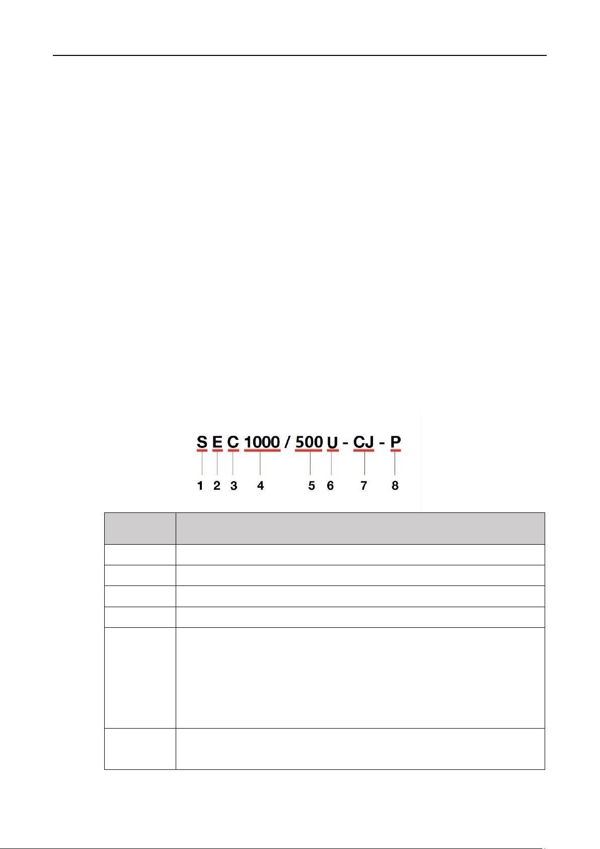
2.2 SEC series products model
NO.
Meaning
1
S: Sinexcel
2
E: Electric Vehicle
3
C: DC Charger
4
Rated output voltage: 1000Vdc
5
Output parameter: Be classified as Power Bank and User Terminal
Power Bank: 360 and 480 (optional), referring to the output power of
the whole charging system
User terminal: 200 and 500 (optional), referring to the Max. output
current per connector
6
Device type
F: Flexible power unit (Power Bank)
SEC Series DC Distributed Charger –User Manual
8
U: User Terminal
7
Charging standard: Only optional for User Terminal. Null for Power
Bank.
C: CCS, referring to CCS Combo connector
J: JAP, referring to Japan standard connector
N: Null
Can choose C/CC/CJ/N
8
System type, can choose P/D
P: Public equipment, normal DC meter
D: Dedicated equipment, dedicated DC meter
N: Null
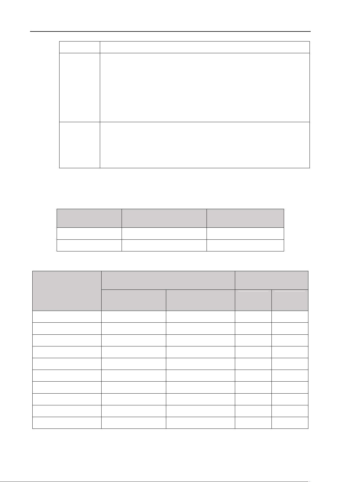
2.3 Models description
2.3.1 Description of Power Bank
Specification
Maximum Output
Power
Maximum Output
Current
SEC1000/360F-N-N
360kW
1206A
SEC1000/480F-N-N
480kW
1608A
2.3.2 Description of User Terminal
Model
Power Distribution
Maximum Output
Current
Connector A
Connector B
Connector
A
Connector
B
SEC1000/200U-C-P
CCS2:200kW
/
200A
/
SEC1000/200U-C-D
CCS2:200kW
/
200A
/
SEC1000/200U-CC-P
CCS2:200kW
CCS2:200kW
200A
200A
SEC1000/200U-CC-D
CCS2:200KW
CCS2:200kW
200A
200A
SEC1000/200U-CJ-P
CCS2:200kW
JAP:100kW
200A
200A
SEC1000/200U-CJ-D
CCS2:200kW
JAP:100kW
200A
200A
SEC1000/200U-CJ-P
CCS2:200kW
JAP:62.5kW
200A
125A
SEC1000/200U-CJ-D
CCS2:200kW
JAP:62.5kW
200A
125A
SEC1000/500U-C-P
CCS2:480kW
/
500A
/
SEC1000/500U-C-D
CCS2:480kW
/
500A
/
SEC Series DC Distributed Charger –User Manual
9
Model
Power Distribution
Maximum Output
Current
Connector A
Connector B
Connector
A
Connector
B
SEC1000/500U-CC-P
CCS2:240kW or
480KW
CCS2:200KW or 0KW
500A
200A
SEC1000/500U-CC-D
CCS2:240kW or
480KW
CCS2:200KW or 0KW
500A
200A
SEC1000/500U-CJ-P
CCS2:240kW or
480KW
JAP:100kW or 0KW
500A
200A
SEC1000/500U-CJ-D
CCS2:240kW or
480kW
JAP:100kW or 0KW
500A
200A
SEC1000/500U-CJ-P
CCS2:240Kw or
480KW
JAP:62.5kW or 0KW
500A
125A
SEC1000/500U-CJ-D
CCS2:240kW or
480kW
JAP:62.5kW or 0KW
500A
125A
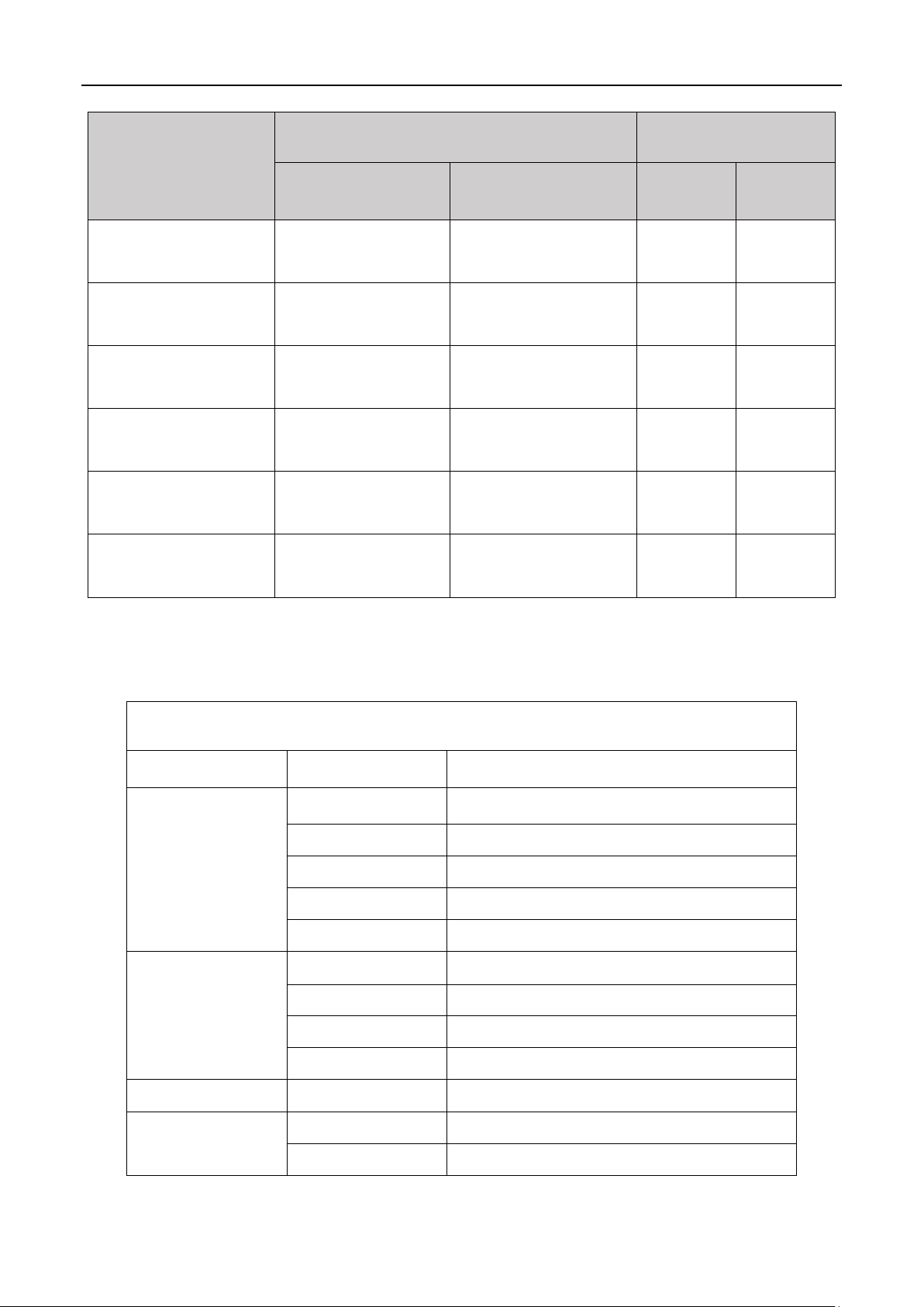
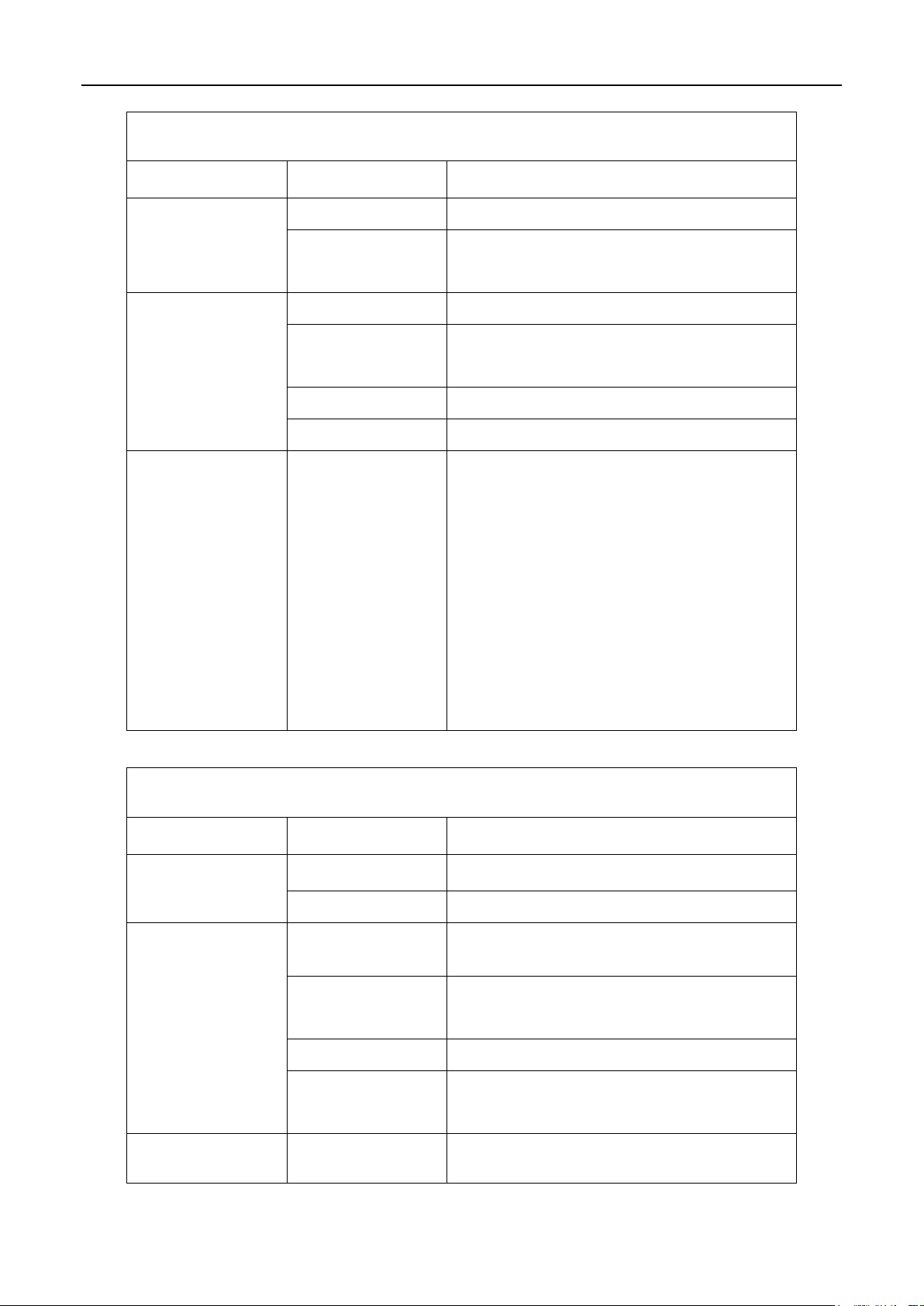
2.4 Product technical specifications
Technical Specifications of Power Bank
Category
Item
Parameter
Input
Characteristic
Input
3P+N+PE
Input Voltage
AC 380~400V
Frequency
50/60Hz
Power Factor
0.99
THDi
<5%
Output
Characteristic
Output Voltage
DC 150-1000 Vdc
Rated Power
360-480kW
Max current
1206/1608A
Efficiency
94% @half load
Standard
System Standard
IEC 61851
Others
Dimensions
W1400*D1000*H2100 mm
Protection Level
IP55
SEC Series DC Distributed Charger –User Manual
10
Technical Specifications of Power Bank
Category
Item
Parameter
Weight
≤850kg
Communication
Protocol
OCPP1.6/2.0(Upgrade)
Environmental
Conditions
Cooling Method
Forced air cooling
Operating
Temperature
-25℃~+65 ℃(Derating over 50℃)
Humidity
5%~95%
Altitude
≤2000m, derating over 2000m
Protection
Lightning protection
Emergency protection
Overload protection
Short - circuit protection
Leakage protection
Overcharge protection
Over/Under voltage protection
Reverse connection protection
Over temperature protection
Technical Specification of User Terminal
Category
Item
Parameter
Input
Characteristic
Operating Voltage
AC230V
Input DC Voltage
DC 150-1000V
Output
Characteristic
Output Voltage
DC 150-1000 V
Max Output
Power
480kW
Max Current
500A
Connector
Standard
IEC 62196
Standard
System Standard
IEC 61851

SEC Series DC Distributed Charger –User Manual
11
Technical Specification of User Terminal
Category
Item
Parameter
Others
Energy Meter
DC meter
Connector Type
1(CCS2) OR 2 (CCS2+JAP or CCS2+CCS2)
Network Interface
4G/LAN
Dimensions
W750*D400*H2100 mm
Protection Level
IP55
Weight
≤225kg
Cable Length
5m (Optional for liquid cooling in 3.5m)
Communication
Protocol
OCPP1.6/2.0(Upgrade)
Screen
7 inches
Payment
QR code/Swiping card/NFC (Optional)
Environmental
Conditions
Cooling Method
Liquid cooling/Air cooling
Operating
Temperature
-25~65 ℃(Derating over 50℃)
Humidity
5%~95%
Altitude
≤2000m
Protection
DC Over current protection
Lightning protection
Emergency protection
Overload protection
Short-circuit protection
Leakage protection
Overcharge protection
Over/Under voltage protection
Reverse connect protection
Over temperature protection

SEC Series DC Distributed Charger –User Manual
12
2.5 Product Features
The maximum charging power can reach 480kW, and there are various power configurations
from 360kW to 480kW to meet the customized needs.
The system includes Power Bank and User Terminals, one Power Bank can provide power to
three User Terminals to meet the needs of charging multiple vehicles simultaneously.
The liquid-cooled User Terminal can automatically allocate power according to vehicle needs
and can achieve 480kW high power charging.
Constant power charging method provides high charging efficiency, simple operation, and
reliable performance.
Ultra-wide output voltage range. The maximum output voltage can reach DC1000V, which
can not only meet the low-voltage charging of smaller vehicles, but also meet the charging
needs of buses and other high-voltage vehicles.
The system has multiple protection functions for hazards such as overload, short circuit,
leakage, lightning, overcharge, overvoltage, reverse connection and overtemperature.
The intelligent standby mode can effectively reduce the operating cos[t of the customer's
entire project life cycle and improve the yield of charging stations.
The cabinet shell is made of stainless steel or hot-dip galvanized sheet + double-layer
spraying material, and the protection level is IP55, which is suitable for outdoor environment.

SEC Series DC Distributed Charger –User Manual
13
2.6 Product View
1. SEC Series Power Bank
Figure 2.6.A SEC Series Power Bank
A LED indicator
D Eye bolts for lifting
B Ventilation area
E Emergency button
C Door handle/ lock
SEC Series DC Distributed Charger –User Manual
14
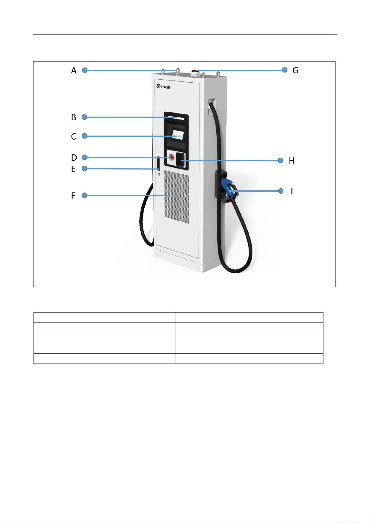
2. SEC Series User Terminal
Figure 2.6.B EC Series User Manual
A Eye bolts for lifting
F Ventilation area
B LED indicator
G Antenna
C Human machine interface
H Card reader
D Emergency button
I Charging connector
E Door handle/ lock
SEC Series DC Distributed Charger –User Manual
15
3 Installation Instruction
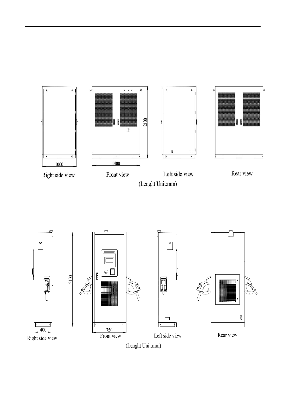
3.1 Dimensions
3.1.1 Power Bank
Figure 3.1.1-A Views and dimensions of SEC Series Power Bank
3.1.2 User Terminal
Figure 3.1.2-A Views and dimensions of SEC Series User Terminal
SEC Series DC Distributed Charger –User Manual
16
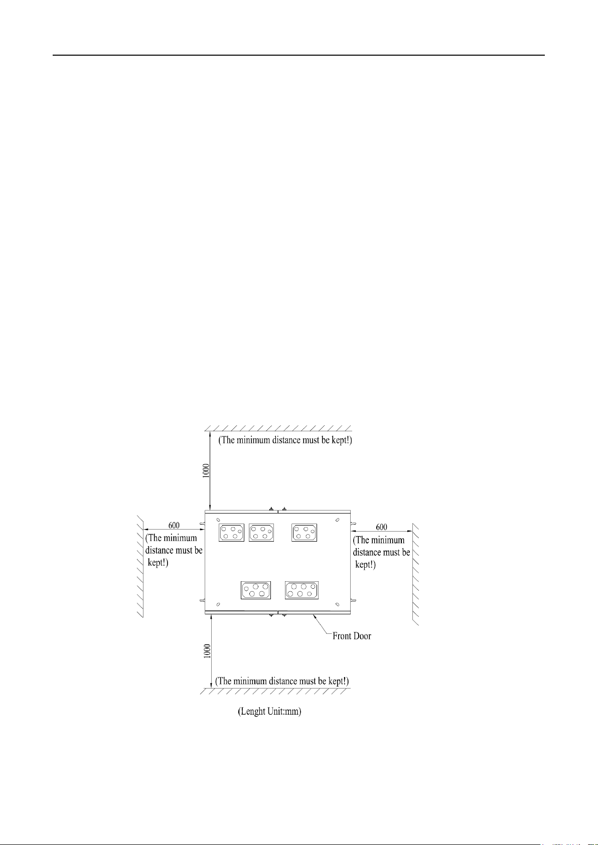
3.2 Installation Requirement
3.2.1 Power Bank
1) Space needs to be reserved for the opening of front and rear doors of the Power Bank.
Please refer to Figure 3.2.1-A for the reserved space dimensions;
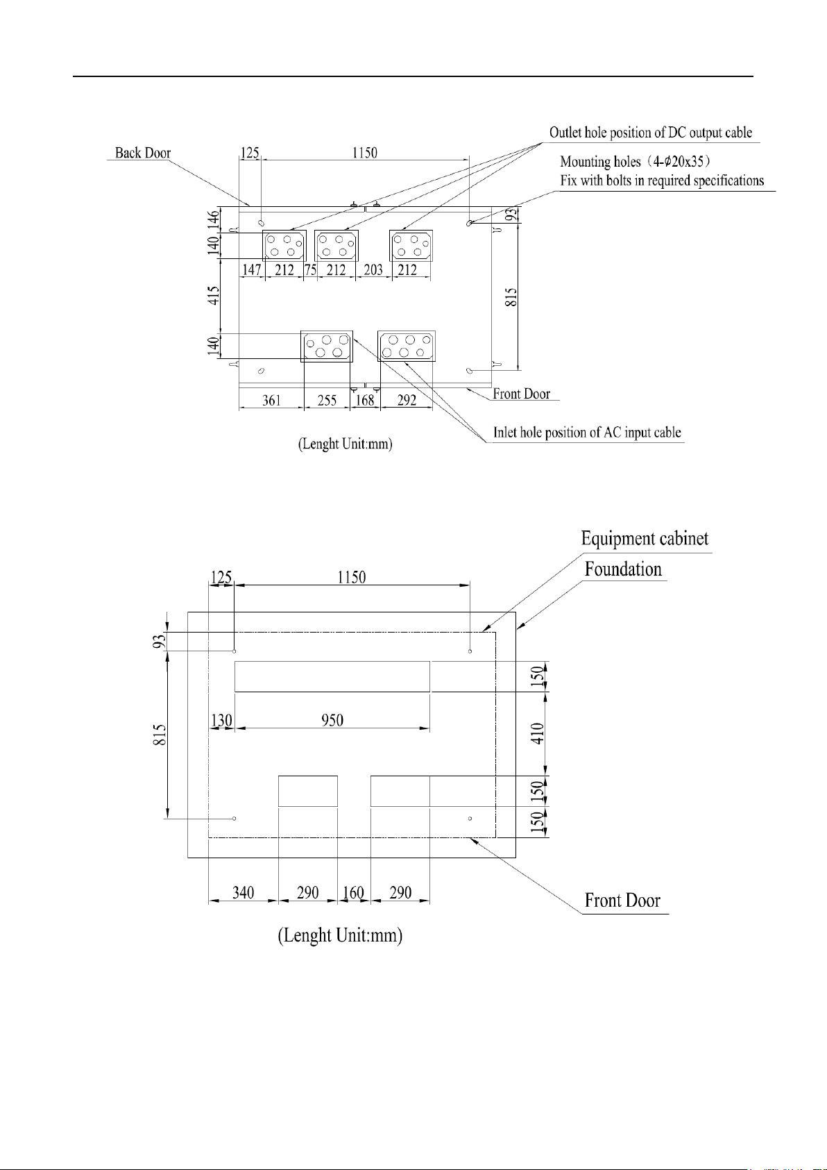
2) Figure 3.2.1-B shows the hole drilling positions and dimensions at the bottom of the Power
Bank;
3) The Power Bank is recommended to be installed on concrete foundation, and the
construction size of the concrete foundation is suggested to be as shown in Figure 3.2.1-C;
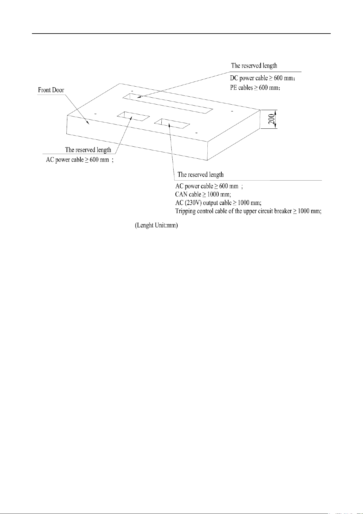
4) The height of the foundation is recommended to be 200mm±20mm, and the vertical
inclination of the installation should not exceed ∠5°. Refer to Figure 3.2.1-D for details;
5) Lay the power cables in advance. Multi-core cables should be stripped under the foundation.
After stripping the AC power cables, the reserved length of the exposed foundation should not be
less than 600mm. The reserved length of signal cables and auxiliary power cables should not be
less than 1000mm. Refer to Figure 3.2.1-D for details;
6) Install 4 M12*80mm stainless steel expansion bolts between the foundation and the Power
Bank cabinet.
Figure 3.2.1-A Power cabinet placement requirements
SEC Series DC Distributed Charger –User Manual
17
Figure 3.2.1-B hole positions and dimensions at the bottom of Power Bank
Figure 3.2.1-C Hole positions and dimensions of the Power Bank concrete foundation
SEC Series DC Distributed Charger –User Manual
18
Figure 3.2.1-D Power bank concrete foundation height and the reserved length of the
input and output cables
This manual suits for next models
14
Table of contents
Other Sinexcel Batteries Charger manuals


Popular Batteries Charger manuals by other brands

Cembre
Cembre BCB1-W Operation and maintenance manual

Matco Tools
Matco Tools MC1220 owner's manual

Leviton
Leviton Evr-Green EVC11-300 user guide

GreenWorks Pro
GreenWorks Pro Ultapower 60V CAC801 Operator's manual

MASCOT
MASCOT 2240P user manual

Accelleron
Accelleron A136-H radial Original assembly instructions


