ADF Web M-Bus User manual

Industrial Electronic Devices
ADFweb.com S.r.l.
User Manual
M
-
Bus / M
-
Bus Wireless / MQTT
Document code: MN67931_ENG Revision 1. Page 2 of 46
NDEX:
Page
INDEX 2
UPDATED DOCUMENTATION 2
REVISION LIST 2
WARNING 2
TRADEMARKS 2
SECURITY ALERT 3
EXAMPLE OF CONNECTION 4
CONNECTION SCHEME 5
CHARACTERISTICS 8
CONFIGURATION 8
POWER SUPPLY 9
FUNCTION MODES 1
LEDS 11
ETHERNET 12
M-BUS 12
M-BUS WIRELESS 13
USE OF COMPOSITOR SW67931 14
NEW CONFIGURATION / OPEN CONFIGURATION 15
SOFTWARE OPTIONS 16
SET COMMUNICATION 18
MQTT SET TOPIC 24
M-BUS 25
UPDATE DEVICE 35
SCAN & DECODE FUNCTION 37
TEMPLATE STRING: DEFINITION OF MQTT
PAYLOAD 38
MECHANICAL DIMENSIONS 41
ORDERING INFORMATIONS 42
ACCESSORIES 44
DISCLAIMER 45
OTHER REGULATIONS AND STANDARDS 45
WARRANTIES AND TECHNICAL SUPPORT 46
RETURN POLICY 46
UPDATED DOCUMENTAT ON:
Dear customer, we thank you for your attention and we remind you that
you need to check that the following document is:
Updated
Related to the product you own
To obtain the most recently updated document, note the “document code”
that appears at the top right-hand corner of each page of this document.
With this “Document Code” go to web page www.adfweb.com/download/
and search for the corresponding code on the page. Click on the proper
“Document Code” and download the updates.
REV S ON L ST:
WARN NG:
ADFweb.com reserves the right to change information in this manual about
our product without warning.
ADFweb.com is not responsible for any error this manual may contain.
TRADEMARKS:
All trademarks mentioned in this document belong to their respective
owners.
Revision
Date Author Chapter
Description
1. 5/12/2 17
Ff All First release version

Industrial Electronic Devices
ADFweb.com S.r.l.
User Manual
M
-
Bus / M
-
Bus Wireless / MQTT
Document code: MN67931_ENG Revision 1. Page 3 of 46
SECUR TY ALERT:
G
ENERAL
NFORMAT ON
To ensure safe operation, the device must be operated according to the instructions in the manual. When using the device, legal and
safety regulation are required for each individual application. The same applies also when using accessories.
NTENDED
U
SE
Machines and systems must be designed so the faulty conditions do not lead to a dangerous situation for the operator (i.e.
independent limit switches, mechanical interlocks, etc.).
Q
UAL F ED
P
ERSONNEL
The device can be used only by qualified personnel, strictly in accordance with the specifications.
Qualified personnel are persons who are familiar with the installation, assembly, commissioning and operation of this equipment and
who have appropriate qualifications for their job.
R
ES DUAL
R
SKS
The device is state-of-the-art and is safe. The instruments can represent a potential hazard if they are inappropriately installed and
operated by untrained personnel. These instructions refer to residual risks with the following symbol:
This symbol indicates that non-observance of the safety instructions is a danger for people that could lead to serious injury or
death and / or the possibility of damage.
CE
CONFORM TY
The declaration is made by our company. You can send an email to [email protected]om or give us a call if you need it.

Industrial Electronic Devices
ADFweb.com S.r.l.
User Manual
M
-
Bus / M
-
Bus Wireless / MQTT
Document code: MN67931_ENG Revision 1. Page 4 of 46
EXAMPLE OF CONNECT ON:
Industrial Electronic Devices
ADFweb.com S.r.l.
User Manual
M
-
Bus / M
-
Bus Wireless / MQTT
Document code: MN67931_ENG Revision 1. Page 5 of 46
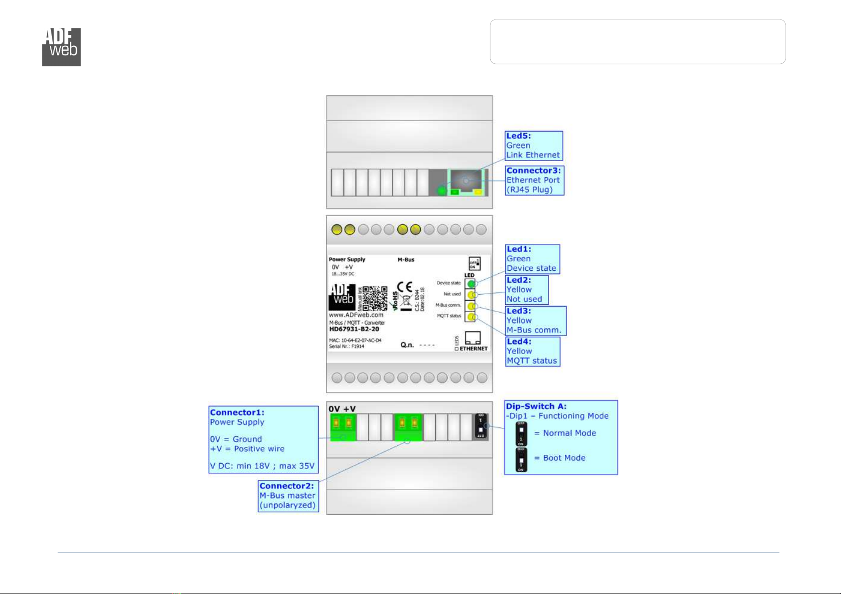
CONNECT ON SCHEME:
Figure 1a: Connection scheme for HD67931 B2 xxx

Industrial Electronic Devices
ADFweb.com S.r.l.
User Manual
M
-
Bus / M
-
Bus Wireless / MQTT
Document code: MN67931_ENG Revision 1. Page 6 of 46
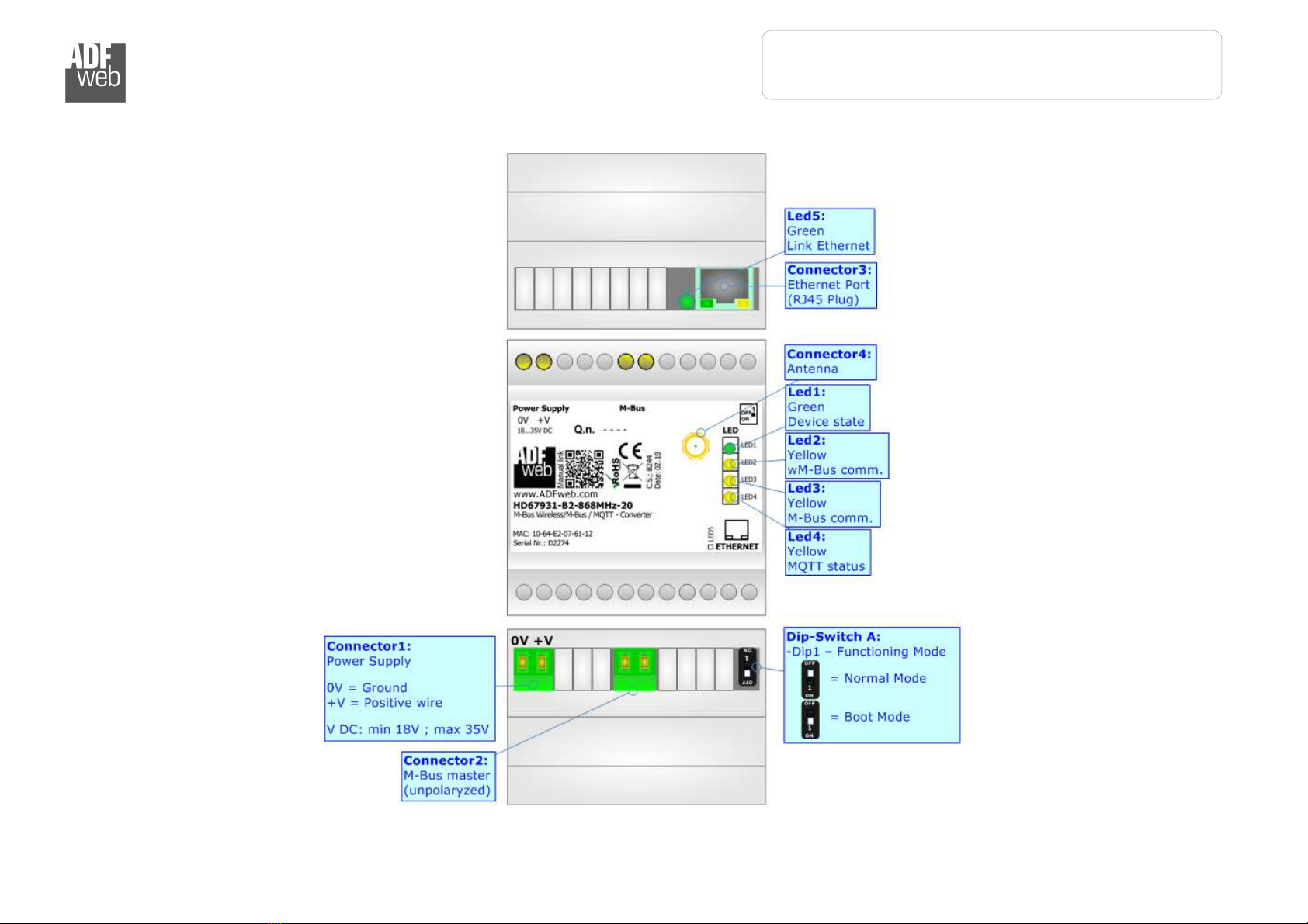
Figure 1b: Connection scheme for HD67931 B2 xxxMHz 0
Industrial Electronic Devices
ADFweb.com S.r.l.
User Manual
M
-
Bus / M
-
Bus Wireless / MQTT
Document code: MN67931_ENG Revision 1. Page 7 of 46
Figure 1c: Connection scheme for HD67931 B2 xxxMHz xxx

Industrial Electronic Devices
ADFweb.com S.r.l.
User Manual
M
-
Bus / M
-
Bus Wireless / MQTT
Document code: MN67931_ENG Revision 1. Page 8 of 46
CHARACTER ST CS:
The HD67931-B2-xxx is a M-Bus / M-Bus Wireless / MQTT Converter.
It allows the following characteristics:
Electrical isolation between Ethernet and M-Bus;
Mountable on 35mm Rail DIN;
Wide power supply input range: 18…35V DC;
Wide temperature range: -4 °C / 85°C [-4 °F / +185°F].
CONF GURAT ON:
You need Compositor SW67931 software on your PC in order to perform the following:
Define the parameter of MQTT;
Define the parameter of M-Bus line;
Define the parameter of M-Bus Wireless line;
Define which M-Bus variables are sent to MQTT Server;
Update the device.
Industrial Electronic Devices
ADFweb.com S.r.l.
User Manual
M
-
Bus / M
-
Bus Wireless / MQTT
Document code: MN67931_ENG Revision 1. Page 9 of 46
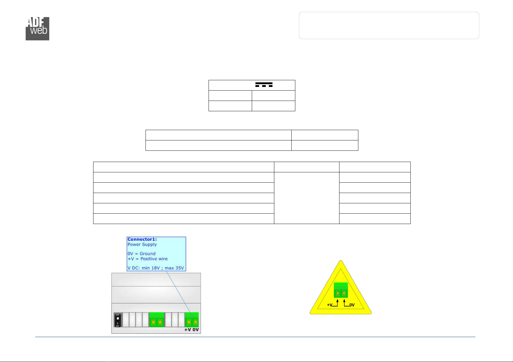
POWER SUPPLY:
The devices can be powered at 18…35V DC. The consumption depends to the code of the device. For more details see the two tables below.
VDC
Vmin Vmax
18V 35V
Consumption at 24V DC:
Device [W/VA]
HD67931-B2-xxxMHz- 3.5
Device No Load [W/VA]
Full Load [W/VA]*
HD67931-B2-xxxMHz-2 , HD67931-B2-2
3.5
4
HD67931-B2-xxxMHz-4 , HD67931-B2-4 5
HD67931-B2-xxxMHz-8 , HD67931-B2-8 8
HD67931-B2-xxxMHz-16 , HD67931-B2-16 14
HD67931-B2-xxxMHz-25 , HD67931-B2-25 3
* This value is with all the Slave M-Bus devices of the code (2 , 4 , 8 , 16 , 25 ) connected to the line (wired side)
HD67
931
-
B2
Caution: Not reverse the polarity power

Industrial Electronic Devices
ADFweb.com S.r.l.
User Manual
M
-
Bus / M
-
Bus Wireless / MQTT
Document code: MN67931_ENG Revision 1. Page 1 of 46
FUNCT ON MODES:
The device has got two functions mode depending of the position of the ‘Dip1 of Dip-Switch A’:
The first, with ‘Dip1 of Dip-Switch A’ at “OFF” position, is used for the normal working of the device;
The second, with ‘Dip1 of Dip-Switch A’ at “ON” position, is used for uploading the Project and/or Firmware.
For the operations to follow for the updating, see ‘UPDATE DEVICE’ section.
According to the functioning mode, the LEDs will have specifics functions, see ‘LEDS’ section.
Industrial Electronic Devices
ADFweb.com S.r.l.
User Manual
M
-
Bus / M
-
Bus Wireless / MQTT
Document code: MN67931_ENG Revision 1. Page 11 of 46
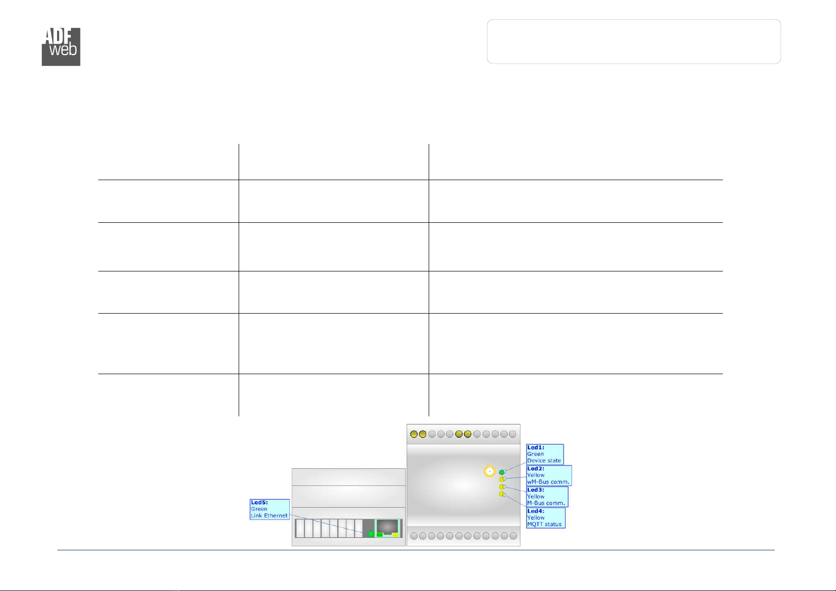
LEDS:
The device has got two LEDs that are used to give information of the functioning status.
The various meanings of the LEDs are described in the table below.
LED Normal Mode Boot Mode
1: Device State (green) Blinks slowly (~1Hz) Blinks quickly: Boot state
Blinks very slowly (~0.5Hz): update in progress
2: wM-Bus comm.
(yellow)
Blinks quickly when a M-Bus
Wireless message is received (only
if M-Bus Wireless is present)
Blinks quickly: Boot state
Blinks very slowly (~0.5Hz): update in progress
3: M-Bus comm. (yellow)
Blinks quickly when a reply to a M-
Bus request arrives (only if M-Bus
is present)
Blinks quickly: Boot state
Blinks very slowly (~0.5Hz): update in progress
4: MQTT status (yellow)
ON: MQTT not connected
OFF: MQTT connected
Blinking: MQTT communication
Blinks quickly: Boot state
Blinks very slowly (~0.5Hz): update in progress
5: Ethernet Link (green) ON: Ethernet cable connected
OFF: Ethernet cable disconnected
ON: Ethernet cable connected
OFF: Ethernet cable disconnected

Industrial Electronic Devices
ADFweb.com S.r.l.
User Manual
M
-
Bus / M
-
Bus Wireless / MQTT
Document code: MN67931_ENG Revision 1. Page 12 of 46
ETHERNET:
The Ethernet connection must be made using Connector3 of HD67931-B2 with at least a Category 5E
cable. The maximum length of the cable should not exceed 1 m. The cable has to conform to the T568
norms relative to connections in cat.5 up to 1 Mbps. To connect the device to an Hub/Switch is
recommended the use of a straight cable, to connect the device to a PC/PLC/other is recommended the
use of a cross cable.
M-BUS:
The M-Bus is a unpolarized bus.
A two wire standard telephone cable (JYStY N*2* .8 mm) is used as the transmission medium for the M-Bus. The maximum distance
between a slave and the repeater is 35 m; this length corresponds to a cable resistance of up 29Ω. This distance applies for the standard
configuration having Baud rates between 3 and 96 Baud, and a maximum of 25 slaves. The maximum distance can be increased by
limiting the Baud rate and using fewer slaves, but the bus voltage in the space state must at no point in a segment fall below 12V, because
of the remote powering of the slaves. In the standard configuration the total cable length should not exceed 1 m, in order to meet the
requirement of a maximum cable capacitance of 18 nF. (Taken from M Bus specifics)

Industrial Electronic Devices
ADFweb.com S.r.l.
User Manual
M
-
Bus / M
-
Bus Wireless / MQTT
Document code: MN67931_ENG Revision 1. Page 13 of 46
M-BUS W RELESS:
The standards of M-Bus Wireless are specified in EN 13757-4. The signal is @ 169 MHz or
433 MHz or 868 MHz (in relation to the order code).
The Antenna connector is a SMA Female (‘Female Outer Shell’ and ‘Female Receptacle’) so
the Antenna must have a SMA Male connector.

Industrial Electronic Devices
ADFweb.com S.r.l.
User Manual
M
-
Bus / M
-
Bus Wireless / MQTT
Document code: MN67931_ENG Revision 1. Page 14 of 46
USE OF COMPOS TOR SW67931:
To configure the Converter, use the available software that runs with Windows called SW67931. It is downloadable on the site
www.adfweb.com and its operation is described in this document. The software works with MS Windows (XP, Vista, Seven, 8, 1 ; 32/64bit).
When launching the SW67931, the window below appears (Fig. 2).
Note:
It is necessary to have installed .Net Framework 4.
Figure 2: Main window for SW67931

Industrial Electronic Devices
ADFweb.com S.r.l.
User Manual
M
-
Bus / M
-
Bus Wireless / MQTT
Document code: MN67931_ENG Revision 1. Page 15 of 46
NEW CONF GURAT ON / OPEN CONF GURAT ON:
The “New Configuration” button creates the folder which contains the entire device’s configuration.
A device’s configuration can also be imported or exported:
To clone the configurations of a Programmable “M-Bus / M-Bus Wireless / MQTT -
Converter” in order to configure another device in the same manner, it is necessary to
maintain the folder and all its contents;
To clone a project in order to obtain a different version of the project, it is sufficient to
duplicate the project folder with another name and open the new folder with the
button “Open Configuration”.

Industrial Electronic Devices
ADFweb.com S.r.l.
User Manual
M
-
Bus / M
-
Bus Wireless / MQTT
Document code: MN67931_ENG Revision 1. Page 16 of 46
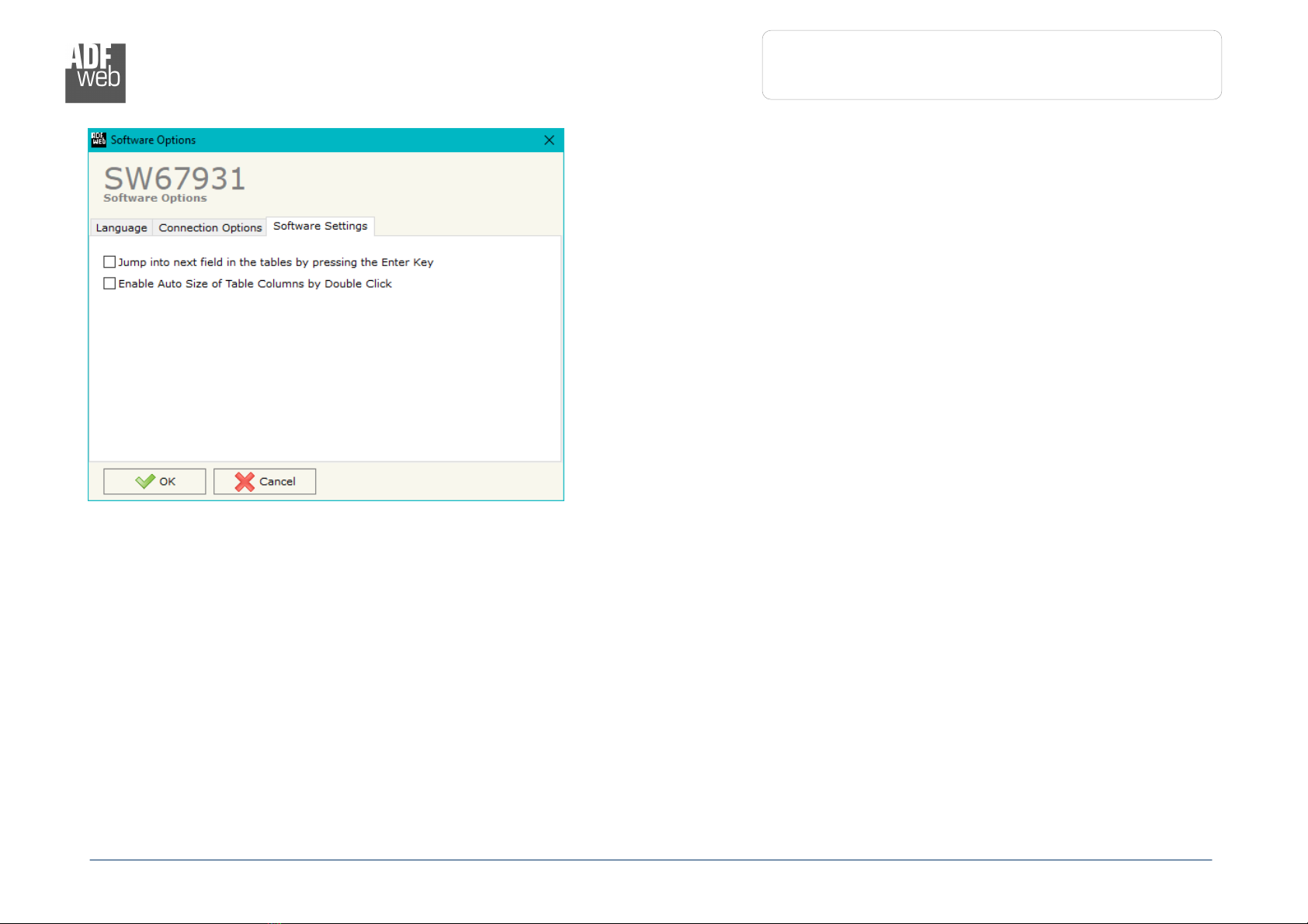
SOFTWARE OPT ONS:
By pressing the “Settings” ( ) button there is the possibility to change the language of the software and check the updatings for the
compositor.
In the section “Language” it is possible to change the language of the
software.
In the section “Connection Options”, it is possible to check if there are some
updatings of the software compositor in ADFweb.com website.
Checking the option “Check Software Update at Start of Program”, the
SW67931 check automatically if there are updatings when it is launched.
Industrial Electronic Devices
ADFweb.com S.r.l.
User Manual
M
-
Bus / M
-
Bus Wireless / MQTT
Document code: MN67931_ENG Revision 1. Page 17 of 46
In the section “Software Settings”, it is possible to enable/disable some
keyboard’s commands for an easier navigation inside the tables contained in
the different sections of the software.
Industrial Electronic Devices
ADFweb.com S.r.l.
User Manual
M
-
Bus / M
-
Bus Wireless / MQTT
Document code: MN67931_ENG Revision 1. Page 18 of 46
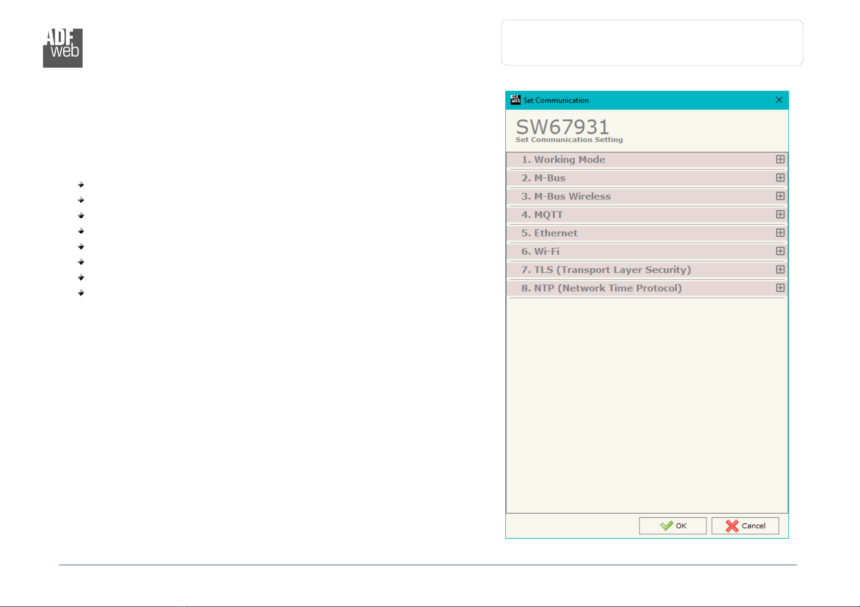
SET COMMUN CAT ON:
By Pressing the “Set Communication” button from the main window for SW67931
(Fig. 2) the window “Set Communication” appears (Fig. 3).
The window is divided in different sections in order to define the different
parameters of the converter:
Working Mode
M-Bus
M-Bus Wireless
MQTT
Ethernet
Wi-Fi
TLS (Transport Layer Security)
NTP (Network Time Protocol)
Figure 3a: “Set Communication” window
Industrial Electronic Devices
ADFweb.com S.r.l.
User Manual
M
-
Bus / M
-
Bus Wireless / MQTT
Document code: MN67931_ENG Revision 1. Page 19 of 46
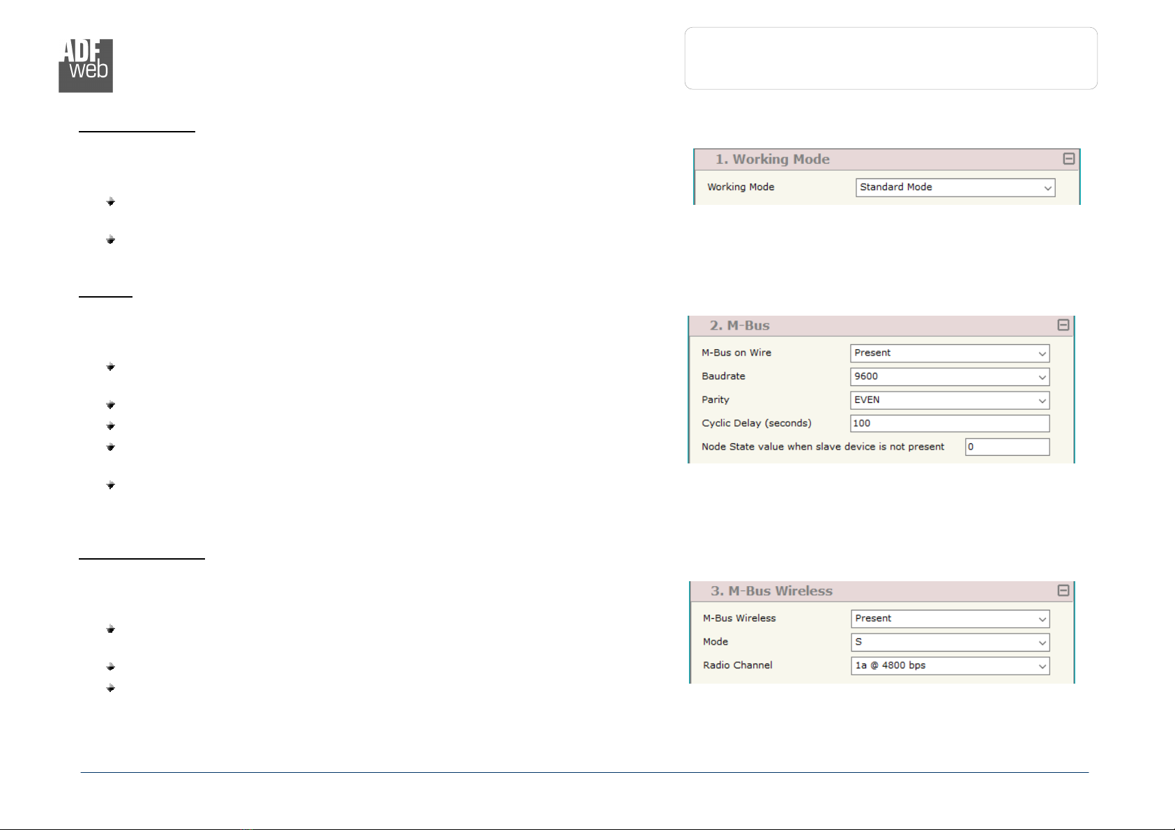
Figure 3b: “Set Communication
Working Mode” window
Figure 3c: “Set Communication
M
Bus” window
Figure 3d: “Set Communication
M Bus Wireless”
window
W
ORK NG
M
ODE
:
This section is used to define the working mode of MQTT side of the converter. It is
possible to define:
Standard Mode: on MQTT side, the data inside the payload of the messages
are already readable and coded in relation to the user definition.
Raw Mode: on MQTT side, it is possible to see the M-Bus responses in raw,
without any decoding.
M-B
US
:
This section is used to define the main parameters of M-Bus line. The means of the
fields are:
In the field “M-Bus on Wire” it is possible to define if the port is present or
not;
In the field “Baudrate” the data rate of the M-Bus line is defined;
In the field “Parity” the parity of the M-Bus line is defined;
If the field “Cyclic Delay” the delay (expressed in seconds) between two M-
Bus scanning is defined;
In the field “Node State value when slave device is not present” it is
possible to insert the value to assign to the “Node State” when the Gateway
doesn’t find the interrogated M-Bus slave.
M-B
US
W
RELESS
:
This section is used to define the main parameters of M-Bus Wireless line. The
means of the fields are:
In the field “M-Bus on Wireless” it is possible to define if the port is present
or not;
In the field “Mode” the communication mode is defined;
In the field “Radio Channel” the radio channel is defined (only for 169
MHz).

Industrial Electronic Devices
ADFweb.com S.r.l.
User Manual
M
-
Bus / M
-
Bus Wireless / MQTT
Document code: MN67931_ENG Revision 1. Page 2 of 46
Figure 3e: “Set Communication
MQTT” window
MQTT:
This section is used to define the main parameters of MQTT line. The means of the
fields are:
In the field “Server URL” the URL or the IP Address of the MQTT Server is
defined;
In the field “Server Port” the port used for MQTT communication is defined;
In the field “Client D” the Client ID of the converter is defined (if ned);
In the field “Keep Alive (seconds)” the delay with which the Keep Alive
message is sent on MQTT is defined;
If the field “Clean Session” is checked, the last MQTT messages are deleted by
the Server and the Client in case of missing ACK. If unchecked, the Server and
the Client hold the last MQTT messages and, in case of incorrect disconnection
or missing ACK, they try to send again them since all the ACK messages are
exchanged correctly (valid only for QoS 1 and QoS 2);
If the field “Will Flag” is checked, the converter will publish the Will topic at the
connection to the Server. With this feature, in case of incorrect disconnection,
the Server will publish this topic to all the MQTT Clients that subscribed it;
In the field “Topic Name Will” the topic used for Will message is defined;
In the field “Message Will” the payload of the Will message is defined;
In the field “Retained Will” the converter will send the Will message with
Retain flag enabled. In this way, the Server will hold the last Will message;
In the field “QoS Will” the QoS type for Will message is defined;
Im the field “Username” the username for the connection to the MQTT server is defined;
In the field “Password” the password for the connection to the MQTT server is defined;
In the field “Template String” the structure of payload for the MQTT messages with the data from M-Bus is defined. See page 38 for
more info.

Industrial Electronic Devices
ADFweb.com S.r.l.
User Manual
M
-
Bus / M
-
Bus Wireless / MQTT
Document code: MN67931_ENG Revision 1. Page 21 of 46
Figure 3f: “Set Com
munication
Ethernet” window
Figure 3g: “Set Communication
Wi Fi” window
E
THERNET
:
This section is used to define the general parameters of Ethernet. The means of the
fields are:
In the field “ p Address” the IP address of the converter is defined;
In the field “SubNet Mask” the Subnet Mask of the converter is defined;
In the field “Gateway” the default gateway of the net is defined. This
feature can be enabled or disabled pressing the Check Box field. This feature
is used for going out of the net;
In the field “DNS” the DNS address is defined. This field is required if the
server address is define by URL and not IP Address.
W
-F
:
This section is used to define the general parameters of Wi-Fi. It is possible to defined
the type of Wi-Fi communication:
Access Point;
Client.
The means of the fields for Access Point configuration are:
In the field “ P Address” the IP address of the converter is defined;
In the field “Subnet Mask” the SubNet Mask of the converter is defined;
In the field “GATEWAY” the default gateway of the net is defined. This feature
can be enabled or disabled pressing the Check Box field. This feature is used
for going out of the net;
In the field “DNS” the DNS address is defined. This field is required if the
server address is define by URL and not IP Address.
In the field “Port” the port used for MQTT communication is defined;
In the field “SS D” the name of the Wi-Fi network to create is defined;
In the field “Password” the password used for Wi-Fi connection is defined;
In the field “Type” the type of security protocol used by the Wi-Fi network is
defined;
This manual suits for next models
2
Table of contents
Other ADF Web Industrial Equipment manuals


