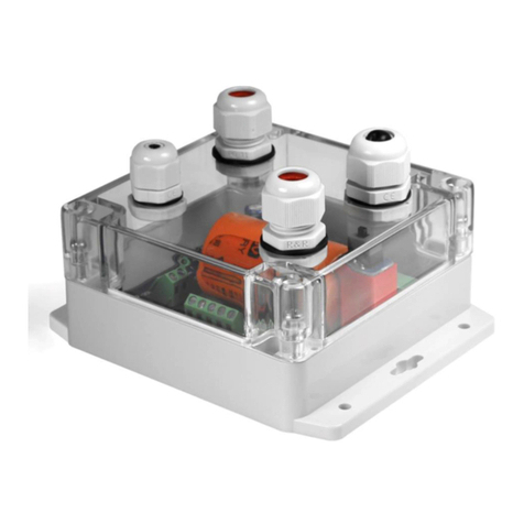
ADGT DTU2 Series User manual

GPRS/NB-IoT Data Loggers
DTU2xx
User Guide
Revision 2.1, November 2021

DTU2xx Data Logger Series
User Guide. r. 2.1 | 2021-11-10
Tel.: +420 538 890 720 2 e-mail: [email protected]
DTU2xx Data Loggers
User Guide (revision 2.1, November 10th, 2021)
This user guide was developed for persons responsible for mounting, configuration and technical maintenance
of the DTU2xx data logger series (hereinafter referred to as DTU or Data Logger). The guide contains
information about the intended purpose, design, technical parameters and operating principles of the DTU.
ADGT systems reserves the right, without any prior notice, to make changes to the operating manual related
to the improvements in hardware and software, as well as to eliminating misprints and inaccuracies.
Safety Instructions
CE WARNING: In a residential environment this product may cause radio interference. In such
cases users may be required to take adequate measures.
WARNINGS!
Do not dispose electronic equipment as unsorted municipal waste. Please use a separate
collection facility or contact the supplier from which this instrument was purchased.
Do not disassemble the device unless you are qualified as service personnel.
AC Input voltage:100-240VAC, 230VAC, 50Hz
Connect the protective grounding conductor of the AC power cord to an earth ground, to avoid
electrical shock.
The equipment should not be serviced when powered up. Make sure to power down the
equipment before performing service activities.
Do not use or install this product near water to avoid fire or shock hazard.
Avoid exposing the equipment to rain or damp areas.
ADGT systems s.r.o
Planichkova, 442/3,
162 00, Prague 6, Prague, Czech Republic
The present document is the property of ADGT systems s.r.o.
Printing is authorized exclusively for private usage.

DTU2xx Data Logger Series
User Guide. r. 2.1 | 2021-11-10
Tel.: +420 538 890 720 3 e-mail: [email protected]
Content
Safety Instructions................................................................................................................................................2
1. Product Overview..............................................................................................................................................4
Product Description....................................................................................................................................................... 4
Technical Specifications................................................................................................................................................ 6
Appearance....................................................................................................................................................................... 8
DTU2xx Interfaces and Wiring Diagrams.............................................................................................................10
Universal GPIOs....................................................................................................................................................10
RS-232 and RS-485 Interfaces ........................................................................................................................13
DTU2xx Operating Modes.........................................................................................................................................15
LED Indication................................................................................................................................................................16
Collection and storage of information .................................................................................................................17
Algorithm of data logger communication..........................................................................................................17
SIM card operation ......................................................................................................................................................17
Operating in NB-IoT network...................................................................................................................................17
Backup battery power supply ..................................................................................................................................18
2. Getting Started................................................................................................................................................ 19
Important safety information...................................................................................................................................19
Installing DTU data logger ........................................................................................................................................19
3. Configuring data logger via PC ..................................................................................................................23
Connecting DTU to PC via USB................................................................................................................................23
DTU Configuring Tool Overview..............................................................................................................................24
Configuring System and Network Setting ..........................................................................................................26
Configuring Inputs.......................................................................................................................................................28
Configuring Serial Interfaces....................................................................................................................................30
Configuring Schedule .................................................................................................................................................32
Configuring SMS Notifications................................................................................................................................34
Configuring Power Consumption Mode When Switching Power to Battery .........................................35
Reboot and Reset .........................................................................................................................................................37
Firmware Update ..........................................................................................................................................................37
Application 1.........................................................................................................................................................39

DTU2xx Data Logger Series
User Guide. r. 2.1 | 2021-11-10
Tel.: +420 538 890 720 4 e-mail: [email protected]
1. Product Overview
Product Description
DTU2xx – a series of battery-powered data loggers
designed for remote metering and monitoring.
Device provides:
Automated data collection from meters with
pulse outputs, meters with serial RS-232 and
RS-485 ports and a wide range of sensors
(resistive, 4-20mA, 1-wire, etc);
Data storage in non-volatile memory;
Wireless data transmission to dispatching
server over GPRS or LTE NB-IoT network.
Data logger is made in an IP30 metal case and equipped with four configurable GPIOs, dual SIM
slots, serial RS-232 and RS-485 ports, and USB port for device configuring.
Devices are powered either from a 230V AC or from a 7-30V DC network (depending on model),
and also have a built-in replaceable 3500 mAh battery to provide backup autonomous operation of
the data logger in the event of external power failure. Battery service life ranges from 4 to 10 years
depending on the model (GPRS or NB-IoT) and its use.
The model range of DTU2xx is represented by the following base models:
Model
Network Type
Transmission Protocol
Power Supply
DTU217
GPRS
TCP
7-30 VDC
DTU217-C*
GPRS
TCP
100-240 VAC
DTU227
LTE NB-IoT
TCP
7-30 VDC
DTU227-U*
LTE NB-IoT
UDP
7-30 VDC
DTU227-C*
LTE NB-IoT
TCP
100-240 VAC
DTU227-UC*
LTE NB-IoT
UDP
100-240 VAC
* Base model options:
-U –UDP protocol. A base software option for all DTU2xx NB-IoT models, which means that the device operates
over the UDP protocol. Otherwise, if there is no ‘-U’ marking, that means that the device operates over TCP protocol.
-C –a built-in 100-240 VAC power supply unit. A base hardware option for all DTU2xx data logger models. Other-
wise, if there is no ‘-C’ marking for these models, that means that the device has 7-30 VDC power supply.
Fig. 1. DTU2xx data logger.
DTU217, DTU227, DTU227-U
7-30 VDC power supply
DTU217-C, DTU227-U, DTU227-UC
100-240 VAC power supply
Fig. 2. DTU2xx base models.

DTU2xx Data Logger Series
User Guide. r. 2.1 | 2021-11-10
Tel.: +420 538 890 720 5 e-mail: [email protected]
DTU2xx base models can be supplied with the set of additional options, which include the following groups:
Hardware Options - minor hardware changes to the device:
-G – RS-485 galvanic isolation
Assembly Options – include replacement or absence of the battery, case and/or type of mounting:
.Z – no battery
.M – no case (for DTU with 7-30 VDC power supply only)
.R – metal DIN rail mounting
.T – wall mounting
The base model in combination with the additional
options constitute a modification of the device and
indicate the difference between a specific modification
and the base model.
Options are added to the name of the base model in
the following sequence:
Base
Model
–
hyphen
Hardware
options
.
dot
Assembly
options (battery,
case, mounting)
Example of a modification name – DTU227-UCG.ZR
Within each group of options, the letters go
alphabetically. If the letters of the option group are not
present in the modification name, then the letter of the
next option group takes its place. If no option is
specified, then we have the base model (see the table
above).
DTU2xx Features
Data transmission according to the schedule, at pressing the button and on the event at
the object.
Date and time regular automatic synchronization.
Dual SIM for communication channel reservation.
Battery discharge monitoring. If the battery is low, a notification will be sent to the server.
Several outputs with a voltage of 3.6V, 5V, 7.5V and 12V for powering external sensors.
Quick and easy device configuration: via PC as well as remotely using web interface.
Application Areas
AMR/AMI Smart Metering Systems (heat, electricity, water, gas)
Automated Control Systems (temperature, leakage, pressure, 1-Wire, current loop)
Power and Energy Industry
Fig. 3. DTU2xx model code designation.

DTU2xx Data Logger Series
User Guide. r. 2.1 | 2021-11-10
Tel.: +420 538 890 720 6 e-mail: [email protected]
Technical Specifications
DTU217
DTU217-C
DTU227
DTU227-U
DTU227-C
DTU227-UC
POWER SUPPLY
Main power supply
source
7-30VDC
100-240VAC/
50Hz
7-30VDC
7-30VDC
100-240VAC/
50Hz
100-240VAC/
50Hz
Max. power consumption
3W1
3W1
1W1
1W1
1W1
1W1
Connector
2-pin terminal block, pitch – 5.08 mm
Backup power supply
source
Li-SOCL2 A-type battery, 3.6V 3200 mAh
Current consumption in
a sleep mode (when
powered by battery)
10 µA (at 2 Hz polling rate), 40 µA (at 20 Hz polling rate),
150 µA (at 100 Hz polling rate)2
Current consumption in
data transfer mode
(when powered by
battery)
150 mA2
36 mA2
36 mA2
Battery life
Not less than four years3
Up to ten years3
CELLULAR NETWORK PARAMETERS
Module frequency range
GSM 850/900/1800/1900
LTE B1/B3/B5/B8/B20/B28 (multiband)
Output power
33dBm (850/900 MHz)
30dBm (1800/1900 MHz)
23dBm±2dB
Data transmission
technology
GPRS class: configured
8/10/auto (up to 12)
NB-IoT Cat NB2
Data transmission rate
up to 85.6 kbps (DL/UL)
125 kbps(DL ) / 150 kbps(UL)
Protocol Stacks
IPv4 TCP
IPv4 TCP
IPv4 UDP
IPv4 TCP
IPv4 UDP
GPIO PARAMETERS
Universal (pulse) inputs
x4 (IO1-IO4)
Connector type
Terminal block, pitch - 3.81mm
Unit of measured value
pulse, ohms, mA, °C, ppm
Pulse counting range
0 - 232
Sensor type
pulse counter, high-frequency pulse counter, signal input, leakage sensor, temperature
sensor, NAMUR, 1-Wire, 4-20 mA current loop, CO2 sensor,
load control, engine hours counter, opening sensor
Polling frequency4
2Hz (default): min. pulse duration – 500ms, max. pulse frequency at the input – 1Hz;
20Hz: min. pulse duration – 50ms, max. pulse frequency at the input – 10Hz;
100Hz: min. pulse duration – 10ms, max. pulse frequency at the input – 50Hz
Relative acceptable pulse
counting error limit
±0,01%
Input condition
Closed, Open, Short circuit, Break
1
Without taking into account the load at the 12V and 7.5V power outputs.
2
If all inputs are configured as counting and the 12V and 7.5V power outputs are turned off.
3
In the operating mode envisaging 3 communication sessions per month.
4
ATTENTION! Increasing the loop polling frequency results in a shorter accumulator battery life.

DTU2xx Data Logger Series
User Guide. r. 2.1 | 2021-11-10
Tel.: +420 538 890 720 7 e-mail: [email protected]
DTU217
DTU217-C
DTU227
DTU227-U
DTU227-C
DTU227-UC
Input resistance
measurement range
0 – 100 kOhm
The line is working properly: open state -3-100 kOhm, closed state - 1-3 kOhm
The line is faulty: line is broken - more than 10kOhm, short circuit - 0-1kOhm
OTHER PORTS & CONNECTORS
Serial Ports
1 x RS-232: non-isolated, Rx, Tx, G signals. Default speed -19200 bps (8N1)
1 x RS-485: non-isolated, A, B signals. Default speed - 19200 bps (8N1).
Load capacity – up to 32 unit load (UL) devices (up to 256 1/8 load devices).
1/2UL = 24kOm. Maximum communication range - up to 1000 m
Power outputs
2 x 3.6V (ENABLED by default)
1 x 5V (DISABLED by default). Enabled when the 1-Wire input is activated ("DS18B20”)
1 x 7.5V (DISABLED by default). Enabled when the "Current loop" input is activated.
1 x 12V (DISABLED by default). Enabled when the "Current loop" input is activated.
SIM
2 x mini-SIM (2FF)
Antenna
1 x SMA-F connector
DEFAULT SETTINGS
Data slice saving
once per hour
Readings transfer to
server
once/day, from 08.00 to 09.00
IOT24.eu server
IP address/server port5
iot24.eu:10002 (GSM)
139.162.147.141:10003 (NB-IoT)
Server connection
on schedule, pressing configuration button (SB),
event at facility (short circuit, break), reboot
Time synchronization
Each connection to server
GENERAL CHARACTERISTICS
Overall dimensions
97 x 88 x 36 mm
Weight
no more than 220 g
Enclosure
aluminum, protection class - IP30
Archive depth
10 years (hourly logging)
Time accuracy
5 sec/day
Average service life
10 years
OPERATING CONDITIONS
Operating temperature
-10...+50°C 6
Relative air humidity
up to 80% at 25°C
Atmospheric pressure
84-106. 7 kPa
5
For devices with a GPRS modem, use a domain name to connect to the server.
For devices with an NB-IoT modem, use only the IP address.
6
When operating from battery at temperatures below 0°C, the battery life could be shorter.

DTU2xx Data Logger Series
User Guide. r. 2.1 | 2021-11-10
Tel.: +420 538 890 720 8 e-mail: [email protected]
Appearance
DTU2xx is a single-board microcontroller device in a metal case with the possibility of mounting on
a DIN rail or on a wall. A description of the buttons and connectors is given below.
Table. 1. DTU2xx buttons and connectors.
Connector
Description
Front side
1
USB
mini-USB B connector for configuring data logger via PC
2
BAT
Power battery switch (default - OFF position)
3
SB
Button for connecting to the server/configuring data logger
4-1
SIM 1
SIM card 1 holder
4-2
Button to remove SIM card 1
5-1
SIM 2
SIM card 2 holder
5-2
Button to remove SIM card 2
6
ANT
SMA-F connector for connecting GSM (NB-IoT) antenna
7
LED indicators (ST1, ST2, ST3)
Rear side
8
XP17
connector
RS-485
A
A+ signal, RS-485 line
B
B- signal, RS-485 line
T
Built-in terminal resistor output (in order to commute terminal resistor,
T-output should be connected to the B- output of RS-485 port)
9
XP27
connector
RS-232
G
Ground
TX
RS-232 interface TX data output
RX
RS-232 interface RX data input
7
Mating part is a 3-pin terminal block with a screw clip (pitch - 3.81 mm).
Fig. 4 DTU2xx connectors and buttons.

DTU2xx Data Logger Series
User Guide. r. 2.1 | 2021-11-10
Tel.: +420 538 890 720 9 e-mail: [email protected]
Connector
Description
10
XP38
connector
GPIO
G
Ground
IO1
Universal counting/signal Input/Output 1
IO2
Universal counting/signal Input/Output 2
IO3
Universal counting/signal Input/Output 3
IO4
Universal counting/signal Input/Output 4
11
XP48
connector
PW-OUT
G
Ground
3.6V
3.6 V power output
3.6V
3.6 V power output
12
XP58
connector
5V
5 V power output
7.5V
7.5 V power output
12V
12 V power output
13-1
XP69
connector
7-30 VDC
DTU217,
DTU227
G
Ground
V
7-30 VDC power supply input
13-2
XP69
connector
~230 VAC
DTU217-C,
DTU227-C
N
Neutral input of power supply voltage 100-240 VAC
L
Line input of power supply voltage 100-240 VAC
14
Data logger grounding screw
8
Mating part is a 3-pin terminal block with a screw clip (pitch - 3.81 mm).
9
Mating part is a 2-pin terminal block with a screw clip (pitch - 5.08 mm).

DTU2xx Data Logger Series
User Guide. r. 2.1 | 2021-11-10
DTU2xx Interfaces and Wiring Diagrams
Universal GPIOs
The data logger has four independent GPIO inputs-outputs (IO1-IO4), that support the connection of a
wide range of meters and sensors. The inputs can be programmatically configured via the web interface
of https://iot24.eu Cloud server or using the DTU Configuration Tool software.
1. Input types for connecting meters
Depending on the meter to be connected, when setting up the data logger, it is possible to select the
following input types:
Counting - the type of input used when connecting pulse meters with a relay output to DTU,
as well as meters with a NAMUR standard output to control the loop integrity. The inputs are
configured to connect meters with a pulse repetition rate at the outputs of up to 100Hz.
High-frequency meter (or HF pulse meter) - the type of input used when connecting high-
frequency impulse meters to the data logger.
Connection. An example of a possible connection of meters to the data logger is given in figure below.
One wire of the meter is connected to one of the inputs IO1 – IO4. The other wire is connected to the
3.6V - 3.6V low current output. The polarity of the wires is not taken into account when connecting.
Up to four meters can be connected to one data logger on one rail.
After connecting the meters, each input must be configured via the https://iot24.eu web interface or
in the DTU Configuration Tool software. When configuring, you must select the type of input (Pulse
meter or HF pulse meter) and set the threshold resistance values at the input.
Depending on the type of meter, the data logger will record 2 or 4 states at the inputs:
closed and open - if the meters are not equipped with a NAMUR circuit.
closed, open, short circuit (SC), open circuit - if the meters have a NAMUR output.
ATTENTION!
When you select the type of input HF impulse meter, you do not need to set the threshold resistance
value, it will be adjusted automatically.
Fig. 5. Connecting meters to DTU2xx.

DTU2xx Data Logger Series
User Guide. r. 2.1 | 2021-11-10
2. Type of input for connecting the engine hours meter.
Engine hours meter - the type of input used when connecting to the data logger devices that
require prophylaxis in terms of operating time, for example, pumps, filters, compressors to
maintain pressure in the system. The engine hours meter allows you to keep track of the time
worked by the device to control the remaining resource.
3. Types of inputs for connecting sensors
Sensors of various types can be connected to the inputs IO1 – IO4 of the data logger: resistance,
current loop 4-20mA, 1-Wire, etc. The following types of inputs are available for selection:
Signal - the two-state input used when connecting resistive sensors to the DTU that measure
the resistance for signal transmission (temperature sensors, leakage, magnetic influence, etc.).
The open and closed resistance thresholds for this type of input are manually adjustable.
Leakage sensor - the type of input used when connecting the ADGT leakage sensor to the
data logger.
Connection. The sensor has a two-wire connection scheme: one wire is connected to any of
the IO1-IO4 (“-”) contacts, and the other to the 3.6V (“+”) contact. Connection polarity is not
important. The plate is placed where the leak is most likely to occur.
Temperature sensor (DMT-12) - the type of input used when connecting the ADGT DMT-12
temperature and magnetic sensor to the DTU. The sensor is designed to measure the
temperature of the pipe surface and determine the effect of a magnetic field on meters.
Connection. Magnetic sensors are mounted on both sides of the water meter for high
accuracy in determining the impact, and the temperature sensor is installed on the pipe. The
sensor is connected to the data logger in a two-wire scheme: one wire is connected to any
of the IO1-IO4 (“-”) contacts, and the second to the 3.6V (“+”) contact. One DMT-12 sensor
is provided for one water meter.
Temperature sensor (DT-14), or DS18B20 sensor - the type of input used when connecting
an ADGT DT-14 temperature sensor with a 1-Wire interface to the data logger. DT-14 is a
waterproof temperature sensor of increased accuracy for measuring temperature at objects.
It is a piece of a three-wire loop connected to a temperature-sensitive DS18B20 element.
Fig. 6. Scheme of connecting ADGT sensors to data logger.

DTU2xx Data Logger Series
User Guide. r. 2.1 | 2021-11-10
The sensor converts the temperature into a digital signal and transmits the information to the
data logger. The DTU takes temperature measurements with an accuracy of ± 0.5 ° C every 5
minutes and, according to a schedule, transmits the values to the server.
Connection. The sensor has three wires, but is connected in a two-wire circuit. Connect the
red (power) and black (ground) wires together and connect to pin G of the GPIO terminal
block. Connect the yellow DQ wire (data line) to any of the IO1-IO4 pins. The sensor receives
power from the data line (in "parasitic" mode).
Current Sensor 4-20 ma – the type of input used when connecting 4-20mA current sensors
to the data logger. When this type is selected, a 100 Ohm load resistor is switched on at the
configurable input, and the 12V and 7.5V outputs of the PW-OUT terminal block are
automatically switched on to enable power supply of current sensors.
The sensor can be connected in accordance with the following diagrams:
The sensor is powered from the built-in data logger power supply. The 4-20mA output of
the sensor is connected to any of the IO1-IO4 inputs, and the +Upow output is connected
to one of the DTU power outputs - 7.5V or 12V.
Fig. 7. Connecting the 1-Wire sensor to the data logger.
Fig. 8. Connecting the current sensor to the DTU
(powered by the data logger).

DTU2xx Data Logger Series
User Guide. r. 2.1 | 2021-11-10
The sensor is powered from an external power supply source. Such a scheme is used if the
supply voltage at the DTU outputs (7.5V and 12V) does not correspond to the voltage that
must be supplied to the sensor.
In this case, the sensor is connected according to the diagram below. 4-20mA output is
connected to any of the inputs IO1-IO4 of the DTU, the +Upow contact of the sensor is
connected to the +Upow of the power supply, and the –Upow of the PSU is connected
to any contact G of the data logger.
RS-232 and RS-485 Interfaces
RS-232 and RS-485 interfaces are designed for remote data collection
from devices. DTU allows organizing a transparent communication
channel between serial devices and upper-level software even in cases
where there is no external power supply at the facility, since the device
can operate autonomously, from a 3500 mAh battery.
The interfaces are co-located, so all information received over a
transparent TCP channel goes to both serial ports, and the response
received over any of the interfaces is transmitted into a single
transparent TCP channel. At one point in time, data exchange is possible
between one of the interfaces ("Client") and a remote node ("Server").
The RS-232 interface uses three signals: Rx, Tx, G.
The RS-485 interface supports A (+) and B (-) signals, and also has a
built-in 120Ω (T) terminal resistor output that is connected to the line
when shorted to B (-).
The load capacity of the RS-485 interface allows you to simultaneously connect:
up to 32 devices with a single load (1UL);
up to 64 devices with 1/2-unit load (1 / 2UL);
up to 128 devices with 1/4-unit load (1 / 4UL);
up to 256 devices with 1/8-unit load (1 / 8UL).
Fig. 9. Connecting the current sensor to the DTU
(powered by an external power supply unit).
Fig. 10. RS-232 and RS-485 ports.

DTU2xx Data Logger Series
User Guide. r. 2.1 | 2021-11-10
The value of the input resistance 1/2 of the unit load of the RS-485 driver is 24 kOhm.
ATTENTION!
The number of devices physically connected to the line can be up to 256, but the total number of UL in
one line should not exceed 32. When connecting devices via the RS-485 interface, be sure to take into
account the load and other limitations of the network and meters, for example, the number of devices
supported by the meter protocol.
Data logger supports the following transparent channel operation modes:
Separate transparent channel
10
. When the option is enabled, the data logger starts working
in the "two-channel" mode. On the one hand, the data transfer channel from the GPIO ports
via the ADGT DTU protocol is kept active, and at the same time, a separate transparent
communication channel between RS-232/RS-485 and the upper-level software is activated.
Both channels work in parallel, with a single scheduled communication output.
Combined transparent channel. In this mode, a transparent data transfer channel from serial
ports is combined with a data transfer channel using the ADGT DTU protocol, which allows
you to simultaneously process the archive of readings from the GPIO ports and data from
serial ports. This mode is necessary if the customer wants to integrate the ADGT DTU protocol
into his own data collecting and processing system.
Transparent channel is off. In this mode, data logger does not process commands from serial
ports.
10
The option is applicable only for GPRS data logger.

DTU2xx Data Logger Series
User Guide. r. 2.1 | 2021-11-10
DTU2xx Operating Modes
The device supports several modes of operation:
Sleep mode
The mode of reduced electricity consumption, being in which, the DTU collects data from metering devices
and monitors the state of the inputs. In the sleep mode, the data logger works most of the time, going
into the connection mode only according to the schedule, when setting up the device or in case of
emergency situations.
ATTENTION!
When connected via USB, the device does not go into a sleep mode.
Server connection and data transfer mode
Data transmission from the DTU to the dispatching server occurs via the TCP (GPRS) or TCP/UDP (NB-IoT)
protocol, which has a client-server architecture. The device always works in the "Client" mode and
independently establishes an outgoing connection with the "Server", to which it sends data after the
connection. The default "Server" is the online dispatching server https://iot24.eu. The server is accessed
through the web interface.
Data logger establishes a connection with the server in the following cases:
According to the established schedule for the scheduled transfer of the accumulated archive
readings. Within 2 minutes after connecting, the device transmits data for the past period to the
server, after which it goes into sleep mode until the next activation. If during one connection not
all information is transmitted, the rest of the data will be sent the next time you connect.
When abnormal events occur at the object. Data logger sends alarm messages to the server in the
event of a short circuit, an open circuit, when sensors are triggered, as well as when the maximum
value of the pulse repetition rate at each of the inputs is exceeded.
Fig. 11. DTU2xx in the utility monitoring system.

DTU2xx Data Logger Series
User Guide. r. 2.1 | 2021-11-10
When turning on and rebooting the data logger.
When you press the SB button – data logger setup/connection to the server button.
Configuration mode
The device comes with pre-configured settings and does not require additional configuration. If necessary,
you can change the operating parameters remotely, via the web interface or by locally connecting the
DTU to a PC, using the DTU Configuration Tool software.
LED Indication
DTU2xx data logger has three LED indicators:
ST1–external power indicator
ST2, ST3 –indicators of connection with the server and
data transmission.
LED indicators modes are presented in table below:
Table. 2. DTU2xx LED indication modes.
Function
Condition
Description
External power
connection
ST1 reading is ON
External power supply 12V or 230V connected
ST1 reading is OFF
External power is not connected
Switching the device to
configuration/connec-
tion with the server
mode by pressing the SB
button
ST2 and ST3 flash 3 times
at the same time
The device has entered the USB configuration/
server connection mode
Server connection and
data transfer mode
ST3 flashes 1 time
every 3 seconds
The device has registered
in the GSM/NB-IoT network
ST2 flashes 1 time
every 3 seconds
Initializing the connection to the server
ST2 and ST3 flash
simultaneously
Connection to the server via TCP (UDP)
established/data transmission is in progress
ST2 and ST3 flash
alternately for 3 seconds
All data has been transferred to this communi-
cation session.
The indication is triggered at the end of the
communication session if the connection to the
server was accessed by pressing the SB button.
Fig. 12. LED indicators.

DTU2xx Data Logger Series
User Guide. r. 2.1 | 2021-11-10
Collection and storage of information
After connecting the wires and power supply, the device connects to the server, synchronizes the date
and time parameters and automatically starts collecting data from the meters according to the preset
settings. In accordance with the given configuration, the DTU performs a continuous counting of the
number of pulses for each channel, with a cumulative total, fixing the meter readings at a given frequency
and storing the slices in non-volatile memory.
To store data, a nonvolatile memory (Flash) microcircuit is installed on the board, which stores the
following service and diagnostic information:
•accumulated counting data on an accrual basis (number of pulses);
•firmware version;
•event log: history of software and hardware restarts, history of pressing the data logger setup
button, information about faults at the inputs.
The amount of stored data is determined by the time taken of the slices. With cuts with a frequency of
once an hour, the depth of the archive will be at least 10 years.
Algorithm of data logger communication
When setting up the schedule, the output of the DTU for communication with the server is set in the "hh"
format (hh - hours, minutes are not set), however, if a large number of connected data loggers
communicate at the same time, this can cause a heavy load on the server. In order to reduce the load,
each device communicates with a delay of several minutes ahead of the specified hour. The delay has a
fixed value, which is calculated based on the IMEI number of the connected DTU and can range from 0 to
60 minutes (but not more than 60 min).
SIM card operation
To reserve the GSM/NB-IoT communication channel, the data logger has two SIM card slots (2FF) with
the ability to configure an active card and support for automatic switching between cards in the absence
of communication on one of the cards. Setting the priority of SIM cards is performed only when connected
locally via a PC, in the DTU Configuration Tool. You cannot set a priority SIM card via the web interface.
By default, the data logger is configured for the SIM1 operating mode, which means that SIM-card 1 is
active by default, the modem works on it and if the connection fails, it does not switch to SIM-card 2. The
option Enable control of the SIM-card activity does not work in this case.
In Auto mode, data logger tries to register on a SIM card, the communication session on which was
successfully established earlier (when the data logger is turned on for the first time — on SIM card 1). If
registration is unsuccessful, data logger automatically switches to another SIM card and tries to register
on it. If the communication session was successful, the data logger remains on this SIM card.
Operating in NB-IoT network
In order for the DTU2xx to connect to the NB-IoT network, the name of the operator's NB-IoT network
through which it is planned to transfer data must be indicated in the modem module.
This parameter is called PLMN (public land mobile network) and is a 5-digit mobile network service area
code including the mobile country code (MCC) and the operator's mobile network code (MNC).

DTU2xx Data Logger Series
User Guide. r. 2.1 | 2021-11-10
The PLMN code can be set only when the DTU is connected locally to a PC using the DTU Configuration
Tool.
To set the PLMN code for your device:
1. Ask your service provider for the PLMN code for the NB-IoT network.
2. Install the PLMN code into the DTU module. In the DTU Configuration Tool, on the System tab,
enter the PLMN in the Operator name line.
Backup battery power supply
NB-IoT DTU22x data loggers are supplied with or without a built-in power supply unit (depending on the
model, see Product Description). Therefore, the devices can be powered both from an external 7-30 VDC
source and from the 100-240 VAC network through a two-contact terminal block.
Additionally, data logger is equipped with a built-in Li-SOCL2 ER18505 (3.6V, 3500 mAh) battery, which
when external power is disconnected, ensures full operation of the data logger in an autonomous mode
(GPRS - up to 4 years, NB-IoT - from 4 to 10 years).
Backup battery is replaceable. By default, the battery is in transport mode, that is, it is turned off (the BAT
switch is in the OFF position). To activate the ability to switch the data logger to the stand-alone mode
when the external power is turned off, turn the switch to the ON mode.

DTU2xx Data Logger Series
User Guide. r. 2.1 | 2021-11-10
2. Getting Started
Important safety information
WARNING! Data loggers with the built-
in 100-240V power supply unit
(DTU217-C, DTU227-C, DTU227-UC)
have electronic equipment safety
CLASS I and need to be properly
grounded before applying power.
To ensure reliable grounding of the
device, use a suitable 3mm hole
ring lug.
To connect the ground, follow these steps:
1. Attach grounding wire to grounding ring lug.
2. Unscrew the grounding screw on the rare side of the terminal (near the ground icon.
3. Insert the grounding screw into the hole of the ring lug and then into the hole on the rear
side of the data logger. Use a spring washer between the screw and the DTU to prevent the
connector from loosening.
4. Tighten the grounding screw and the ring lug to the data logger panel. Do not overtighten
the screw!
ATTENTION! DTU217-C, DTU227-C, DTU227-UC have a built-in power supply unit and can be
connected directly to a 100-240V power supply source. Since the device does not have its own
power switch and can be installed into hard-to-reach places (electrical cabinets, etc.), for safety
reasons, equip the device with an external power-off switch. The switch should be placed in an
easily accessible place and its designation should be visually accessible and easily identified by
the function performed.
NOTE: When using a 230v powered DTU2xx-C device, for double protection against electric
shock, use the diagram in the Application 1.
Installing DTU data logger
Before installing the data logger, you need to register on the dispatching server https://iot24.eu and add
your data logger to the server by the IMEI number and PIN code (see on the label of the case cover).
1. Check the data logger for compliance with the completeness of the technical documentation and
make sure that there is no visible damage to the case and markings. Prepare cable glands for
meters and sensors for operation.
2. Install the SIM-card (-s) into the DTU, having previously disabled the PIN codes. To insert a SIM
card, extract a SIM card tray out of the SIM slot by pressing SIM card tray ejection button with a
SIM ejection tool. Place the SIM cards into the trays and insert each tray back until it clicks:
Fig. 13. DTU2xx grounding screw.

DTU2xx Data Logger Series
User Guide. r. 2.1 | 2021-11-10
the SIM1 tray - into the SIM1
slot with the contact pad down
the SIM2 tray - into the SIM2
slot with the contact pad up.
3. Connect the GSM or LTE NB-IoT
SMA-m antenna to the ANT SMA-f
connector.
4. Connect meters and sensors to the
corresponding DTU GPIO
connectors (IO1-IO4). For pinouts
see section Appearance.
Recommended wiring diagrams
are presented in Universal GPIOs.
ATTENTION!
When connecting wires to GPIOs,
take into account:
IO1-IO4 – negative (“–”) pole;
3.6V – positive (“+”) pole power
output contacts.
Fig. 14. Installing SIM cards.
Fig. 15. Connecting antenna.
Fig. 16. Connecting meters.
Table of contents
Other ADGT Data Logger manuals
