ADIRmed Viva ADIME902-WALL-48-GRY User manual
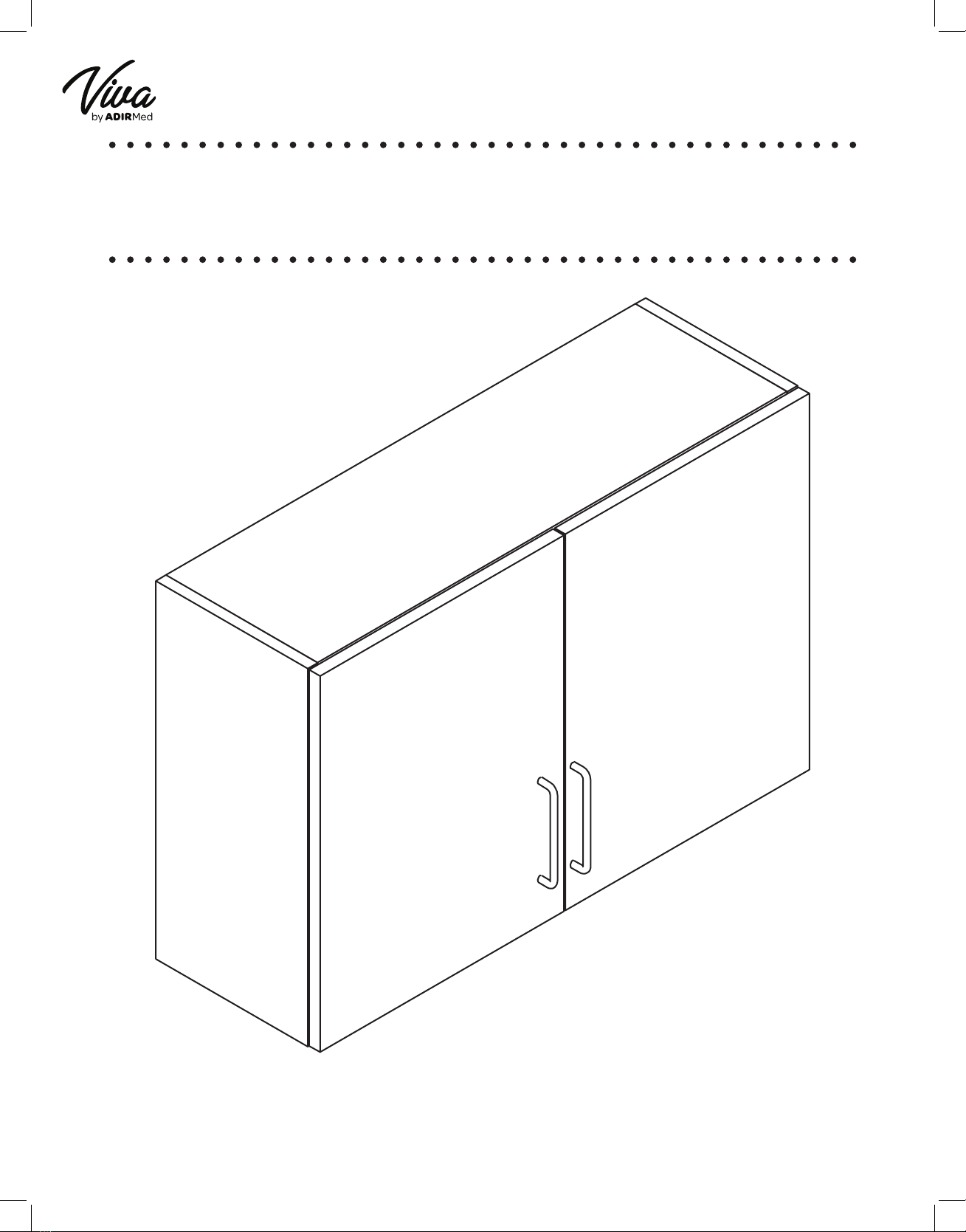
48 INCH WALL CABINET
USER GUIDE
ADIME902-WALL-48-GRY

Thank you
for your
purchase.
Viva by AdirMed maintains
a strong practice of ongoing
development of products and
commercial research.
We recognize that starting and maintaining a medical practice is
expensive. We’ll help make the process cost-eective and elegant.
Additionally, our team of specialists will ensure everything you
need works as eciently as possible, so you can eectively treat
your clients.

Table of Contents
2
3
4
11
17
Parts
Hardware
Assembling Your Wall Cabinet
Hanging Your Wall Cabinet
Warranty

2
Parts
A
Left Panel
C
Middle Panel
B
Right Panel
D
Back Panel
F
Bottom Panel
E
Top Panel
G
Removable Shelf (x2)
I
Center Back Rail
H
Top Back Rail
J
Bottom Back Rail
L
Right Door
K
Left Door
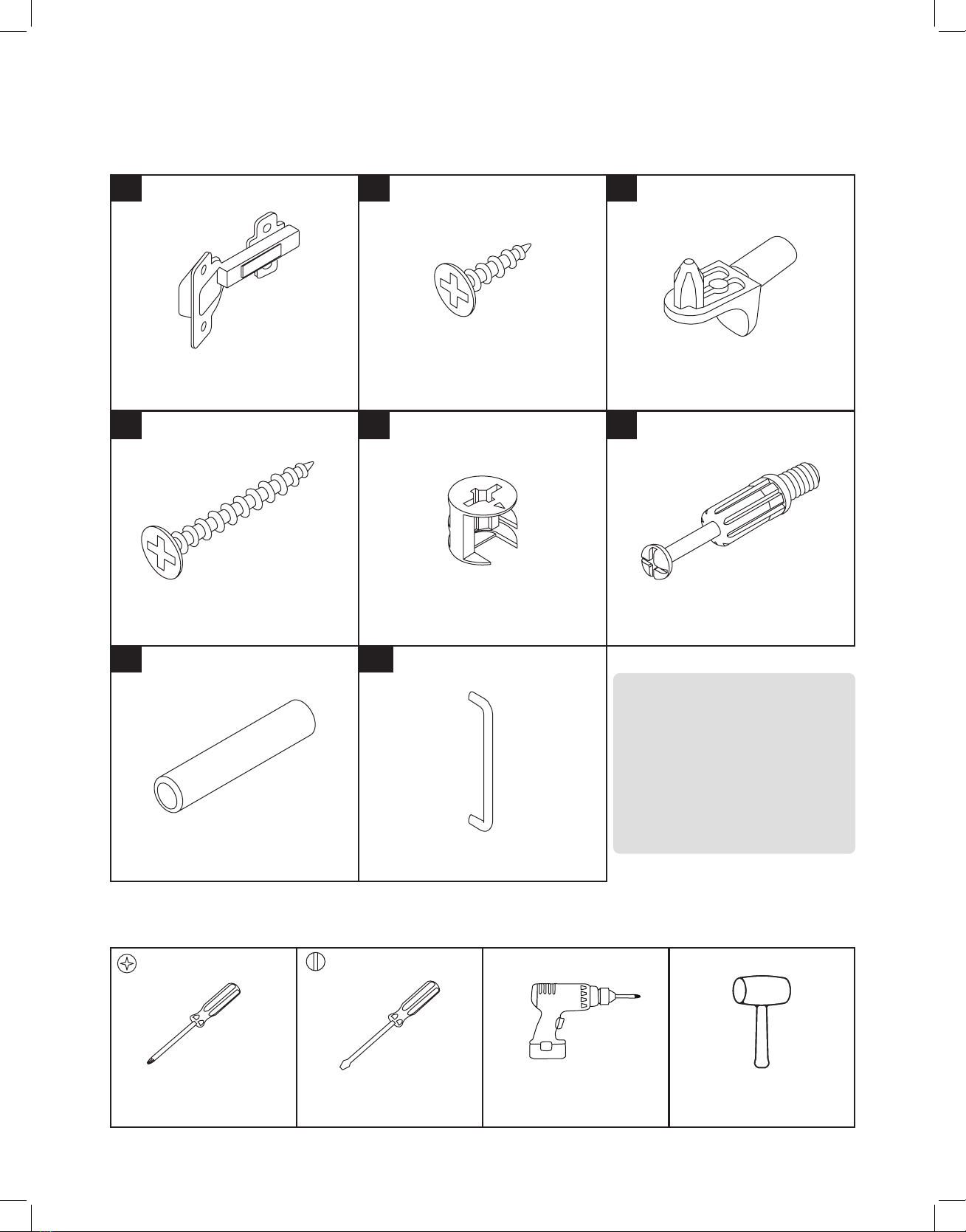
3
1
Hinge (x4)
32
Ø4x15 mm
Wooden Screw (x24)
4
Ø4x30 mm
Wooden Screw (x2)
6
Cam Lock Bolt (x16)
5
Cam Lock (x16)
7
Wooden Dowel (x24)
Shelf Support (x8)
8
Handle (x2)
Hardware
Tools Needed (But Not Included):
Electric Screwdriver Rubber MalletFlat Head Screwdriver
Phillips Head
Screwdriver
• Ø4x15 mm Wooden Screw (x24)
• Ø4x30 mm Wooden Screw (x2)
• Ø15*13 mm Cam Lock (x16)
• Ø8*35 mm Cam Lock Bolt (x16)
• Ø8x40 mm Wooden Dowel (x24)
Hardware Specications:

4
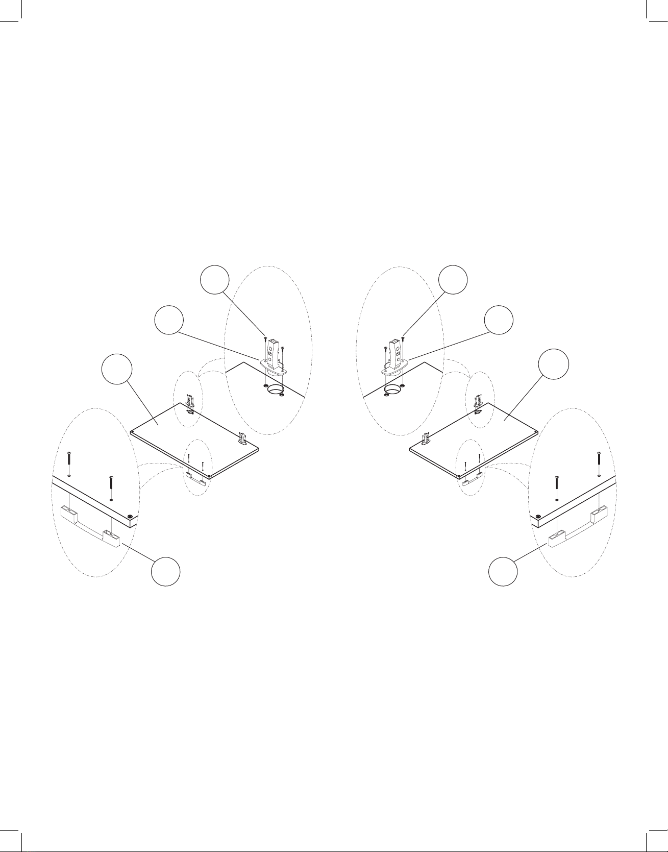
Assembling Your Wall Cabinet
A. Before beginning, ensure you have all the parts and hardware listed above for your wall cabinet.
B. Locate and lay your Bottom Panel (F) on a at surface.
C. Locate the Middle Panel (C), the Top Panel (E), two Wooden Dowels (7), and two Cam Lock Bolts (6).
D. Insert two Wooden Dowels (7), and two Cam Lock Bolts (6) into the four middle predrilled holes on the
Bottom Panel (F).
a. Use a rubber mallet to tap the dowels into place gently.
b. Use a Philips head screwdriver to secure the Cam Lock Bolts (6).
E. Repeat the above steps for the Top Panel (E).
F. Take the Middle Panel (C) and afx the shorter edge to the Bottom Panel (F).
a. Gently tap the Middle Panel (C) with a rubber mallet until ush with the Bottom Panel (F).
G. Line up the hardware installed on the Top Panel (E) with the other edge of the Middle Panel (C).
a. Ensure the etched channel on the Top Panel (E) mirrors the etched channel on Bottom Panel (F).
b. Gently tap it until the Middle Panel (C) and the Top Panel (E) are ush. .
H. Install four Cam Locks (5) in the Middle Panel (C), two per side, and turn to secure the Cam Lock Bolts (6)
in place.
Step 1:
C
E
F
7
5
4x
4x
4x 6
Before starting, ensure you have an open, clean
area to assemble your cabinet. Ensure you have all
the necessary parts and hardware listed above. We
highly recommend hiring a professional contractor
to assemble and install your cabinet(s).
NOTE:

5
A. Turn your structure to rest on the Top Panel (E) and Bottom Panel (F) edges.
a. On both panels, two predrilled holes are at the etched channels’ top and bottom.
b. Gently tap eight Wooden Dowels (7) into both panels.
c. Locate the Top Back Rail (H) and the Bottom Back Rail (J).
d. Attach the Top Back Rail (H) to the Wooden Dowels (7) you installed into the Top Panel (E).
e. Attach the Bottom Back Rail (J) to the Wooden Dowels (7) you installed into the Bottom Panel (F).
f. Tap the Bottom Back Rail (J) and Top Back Rail (H) with a rubber mallet until ush.
B. Lay the Left Panel (A) on a at, clean surface.
C. Install six Wooden Dowels (7) and six Cam Lock Bolts (6) into three of the edges on the Left Panel (A), as
shown.
D. Once the hardware is secure, attach your structure and push it down until it is ush with the Left Panel (A).
E. Install four Cam Locks (5) on the bottom of the Top
Panel (E) and the Bottom Panel (F).
a. Gently tap the Middle Panel (C) with a rubber
mallet until ush with the Bottom Panel (F).
F. Install two Cam Lock (5) on the bottom of the Bottom
Back Rail (J) and the Top Back Rail (H)
a. Turn to secure the Cam Lock Bolts (6) in place.
C
E
E
65
7
F
F
A
J
H
H
7
6x
8x
6x
6x
Step 2:
J

6
A. Locate the Back Panel (D) and slide it between the etched channels on both the Top Panel (E) and the
Bottom Panel (F), as pictured.
7
5
6
D
B
6x
6x
6x
Step 3:
A. Take the Right Panel (B), and lay it on a at, clean surface with the predrilled holes facing up.
B. Along three of the edges on the Right Panel (B), install six Cam Lock Bolts (6) and six Wooden Dowels (7).
C. Lift the Right Panel (B) and line the installed hardware up with the predrilled holes on the Top Panel (E),
Back Panel (D), Top Back Rail (H), and Bottom Back Rail (J).
D. Insert the hardware and push the Right Panel (B) down until it is ush with the rest of the structure.
E. Install six Cam Locks (5) on the Top Panel (E), Back Panel (D), Top Back Rail (H), and Bottom Back Rail (J).
a. Turn to secure the Cam Lock Bolts (6) in place.
Step 4:

7
H
4
J
2x
Step 5:
A. Take one Ø4x30 mm Wooden Screw (4) and secure it to the middle of the Top Back Rail (H), as pictured.
B. Repeat the above step for the Bottom Back Rail (J), as shown.
8
2 2
1 1
4x 4x
2x 2x
KL
8 8
A. Locate the Hinges (1), Ø4x15 mm Wooden Screws (2), the Left Door (K), and the Right Door (L).
B. Adhere the Hinges (1) to the inside of the doors using two screws per Hinge (1), as pictured.
a. Eight screws total will be used between the two doors.
C. Take both Handles (8) and afx them to both doors with their accompanying screws, and thread them
through the predrilled holes on the doors.
D. Secure them in place with a Philips head screwdriver.
Step 6:
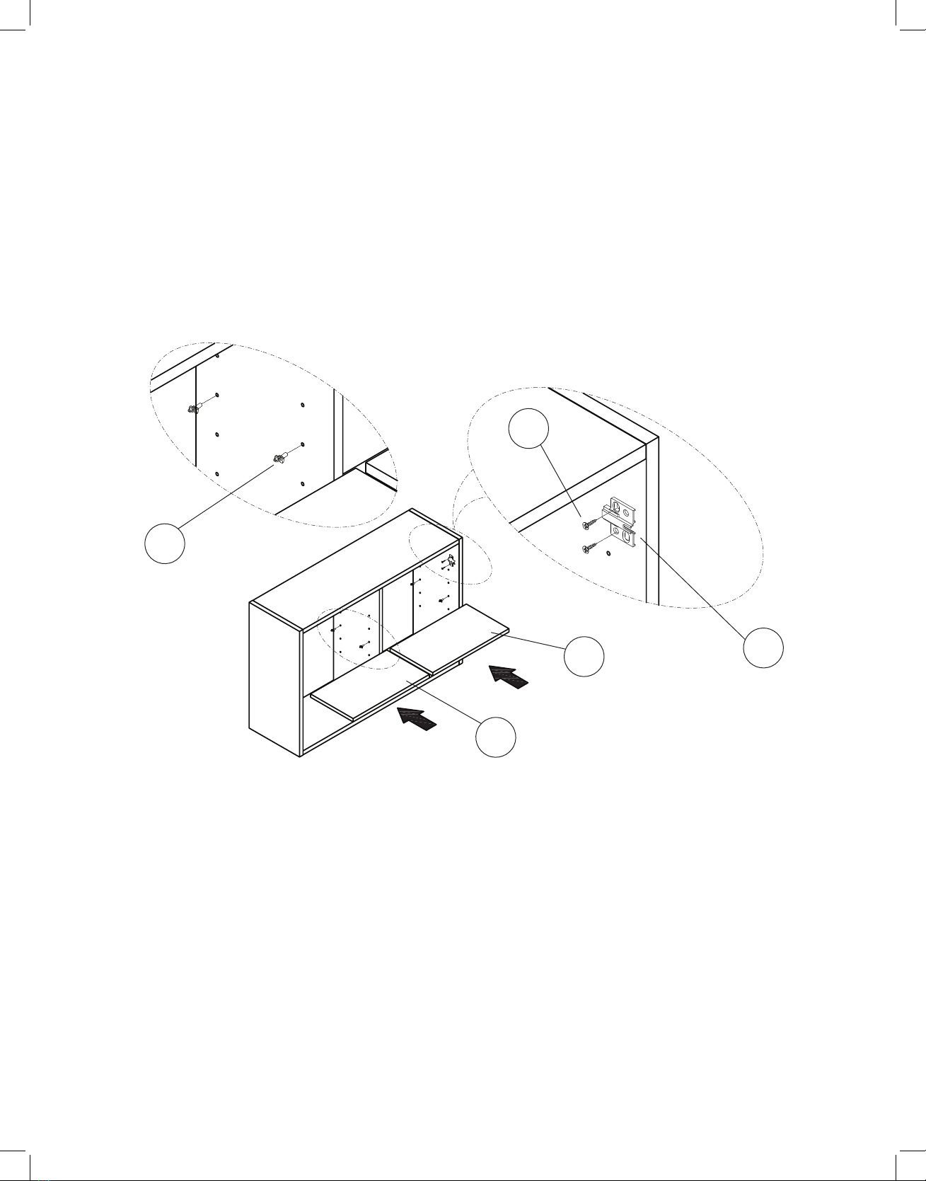
9
A. On the Left Panel (A) and the Right Panel (B), install the other side of the Hinges (1) with two Ø4x15 mm
Wooden Screws (2) per Hinge (1), as pictured.
B. Insert eight Shelf Supports (3), as pictured, and at your desired height.
C. Insert both Removeable Shelves (G) as pictured, and ensure the pegs insert into the shelves.
Step 7:
8x
4x
G
G
3
2
1

10
K
L
1
2
A. Connect the Hinges (1) as pictured and secure them together with one Ø4x15 mm Wooden Screws (2),
per Hinge (1).
a. Four screws total will be used between the two doors.
B. If your doors do not line up, adjust the screws, as shown.
Step 8:
8x
2

11
Hanging Your Wall Cabinet
Parts: Hardware:
Using The French Cleating System
A 1
Top Cleat Plastic Anchors (x4)
B 2
Bottom Cleat
Screws (x4)
(M6 x 70 mm)
Tools Needed (But Not Included):
4 ft Level
Phillips Head
Screwdriver
Drill
Electric
Screwdriver Stud Finder
Tape Measure
9 mm Drill Bit
Pencil
•Before beginning, locate where exactly you want the Wall Cabinet to be installed.
• You must nd at least one stud to mount the French cleating system into.
•Make sure you have all the necessary tools listed above prior to beginning.
•We highly recommend using two people to ensure everything is level and
properly installed.
NOTE:
12
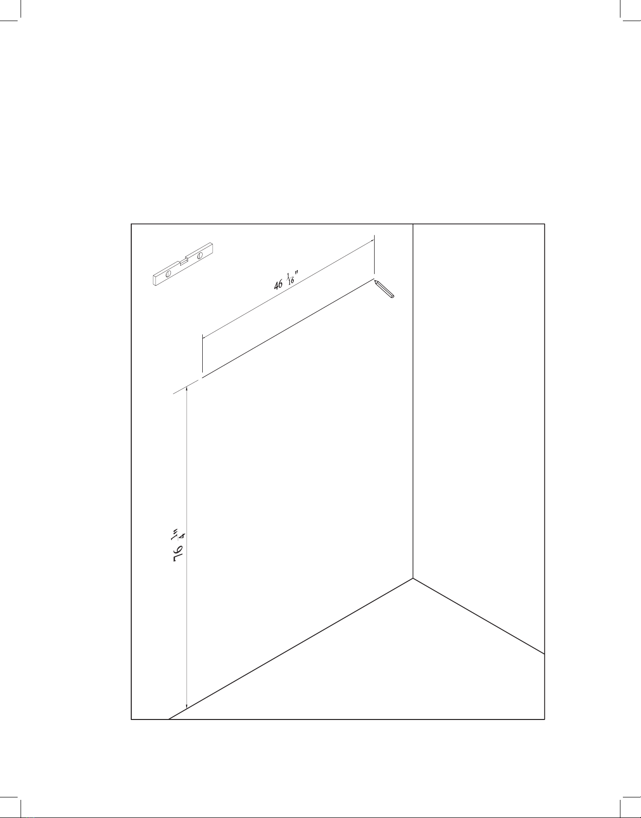
A. Using a stud nder, nd at least one stud that a mounting screw will be secured in before beginning.
B. Taking your tape measure, measure from the ground up 76 1/4”.
a. Mark this measurement on the wall with a pencil.
b. This is the height of your mounting holes.
C. Using the mark on the wall, take your 4-foot level, and measure out 46 1/16”.
a. Mark this line with a pencil going right to the left.
Step 1:
13
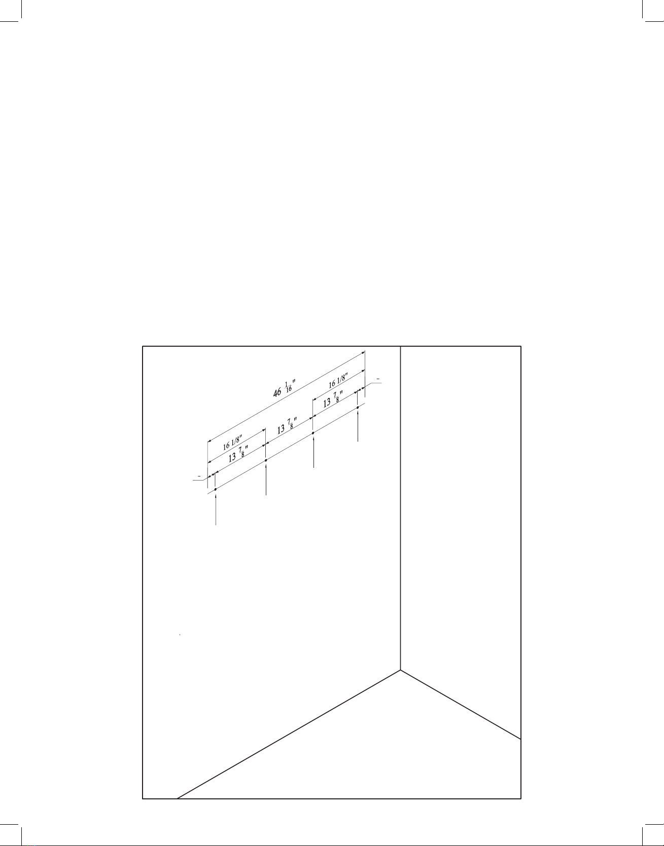
A. Take your tape measure, and starting from the left side of your line, measure from left to right 2 1/4”.
a. Mark this measurement on the wall.
b. This will be your left drill hole for Bottom Cleat (B).
B. Take your tape measure, and starting from the right side of your line, measure from right to left 2 1/4”.
a. Mark this measurement on the wall.
b. This will be your right drill hole for Bottom Cleat (B).
C. Using your tape measure, measure from right to left on your line, 16 1/8”.
a. Mark this measurement on the wall.
b. This will be your 1st central drill hole for Bottom Cleat (B).
D. Using your tape measure, measure from left to right on your line, 16 1/8”.
a. Mark this measurement on the wall.
b. This will be your 2nd central drill hole for Bottom Cleat (B).
Step 2:
21
4''
21
4''
Mark
Mark
Mark
Mark
14
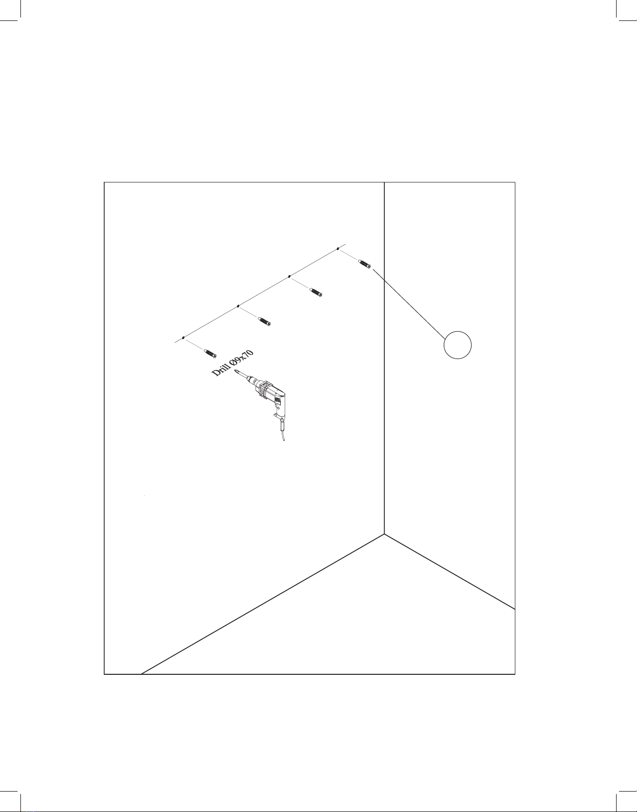
A. Drill the four holes marked on the wall with a 9 mm drill bit at a depth of 2.75”.
B. Insert the four Plastic Anchors (1) into the holes.
Step 3:
1
15
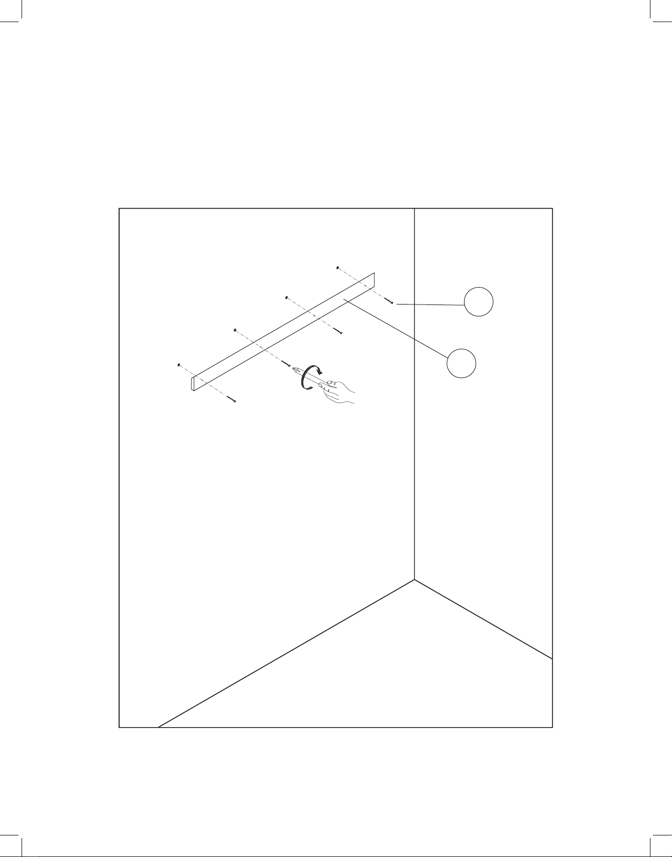
A. Locate the Bottom Cleat (B), and line it up with the holes you drilled in Step 3.
a. Insert the four included Screws (2) into the predrilled holes on the cleat.
b. Secure them in place with either a Philips head screwdriver or an electric screwdriver.
Step 4:
B
2
16
A. With two people, lift your wall cabinet up and over the Bottom Cleat (B).
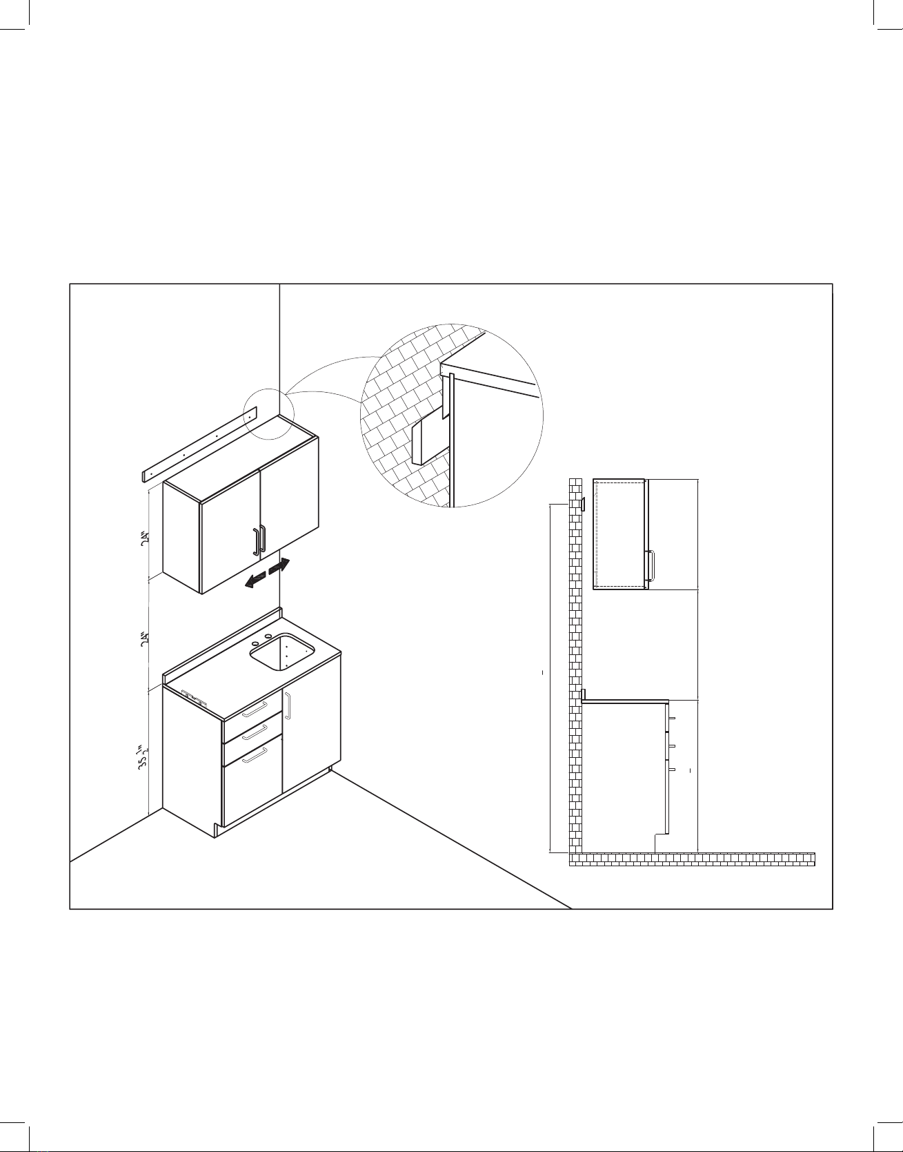
B. Slowly slide the cabinet down until the Top Cleat (A) 45° edge ts securely on the Bottom Cleat’s (B) edge.
Step 5:
33 1
4"24" 24"
76 1
4''

17
Warranty
Adir Corp (the “Company” or “Tiger Companies”) warrants to the purchaser that the product
will be free from defects in workmanship and materials for a period of 3 years from the date
of purchase. The warranty period is not extended if we repair, replace, exchange, or provide a
refund for the product (as determined in our sole discretion). We may change the availability
of this limited warranty at our discretion, but any changes will not be retroactive.
These warranties are not assignable or transferable to any other person, including, without
limitation, any subsequent owner or other transferee of the product.
This Warranty does not apply to: (a) damage caused by misuse, tampering, abuse, neglect, or
accident; (b) damage caused by improper installation, modication, or service; (c) alteration
of the serial number; or (d) use that violates the instructions furnished by the Company will
void this warranty.
The sole responsibility of the Company shall be limited to (a) the repair or replacement (in its
sole discretion) of any component of the product which fails to conform to this; (b) a refund
the purchase price of such product (in its sole discretion), at no cost to the purchaser for the
period of the warranty, or (c) an exchange for a similar product, comparable in function and
price.
Contact the Company directly at 1-(800)-805-1790 to obtain service under this warranty. If
it becomes applicable to send a defective product to the Company, a Return Authorization
Number must rst be obtained from the Company. In order to obtain service under this
warranty, purchaser may be required to provide the Company with the following items
(a) proof of purchase, (b) photographs and or videos (of the damage, and (c) a written
testimonial describing the defect.
Products shipped without prior Return Authorization and Return Authorization Number may
not be accepted, and the Company will not be responsible for their disposition and/or cost of
return to the owner.
The Company will not assume any responsibility for any loss or damage incurred in shipping
and or delivery.
The product(s) must be returned within 14 calendar days of receiving the return authorization
from the Company and must include the original proof of purchase for the warranty to be
honored.
Any implied warranties that the purchaser may have are limited to the duration of the
warranties described above. There are no further warranties that extend or apply beyond the
face hereof, and the Company expressly disclaims and excludes any and all warranties of
merchantability or tness for a particular purpose. Some states do not allow limitations on
how long an implied warranty lasts, so the above limitation may not apply to you.
THE REMEDIES DESCRIBED ABOVE ARE YOUR SOLE AND EXCLUSIVE REMEDIES AND
THE COMPANY’S ENTIRE LIABILITY FOR ANY BREACH OF THIS LIMITED WARRANTY. OUR
LIABILITY SHALL UNDER NO CIRCUMSTANCES EXCEED THE ACTUAL AMOUNT PAID BY
YOU FOR THE DEFECTIVE PRODUCT, NOR SHALL WE UNDER ANY CIRCUMSTANCES BE
LIABLE FOR ANY CONSEQUENTIAL, INCIDENTAL, SPECIAL OR PUNITIVE DAMAGES OR
LOSSES, WHETHER DIRECT OR INDIRECT. SOME STATES DO NOT ALLOW THE EXCLUSION
OR LIMITATIONS OF INCIDENTAL OR CONSEQUENTIAL DAMAGES, SO THE LIMITATION MAY
NOT APPLY TO YOU.
This warranty gives you specic legal rights, and you may also have additional rights which
vary from state to state.
1.
2.
3.
4.
5.
6.
7.
8.
9.
10.
11.

ADIME902-WALL-48-GRY
© 2023 AdirCorp
adircorp.com
Table of contents
Other ADIRmed Indoor Furnishing manuals


Popular Indoor Furnishing manuals by other brands

Homelegance
Homelegance 1711 Assembly instruction

Whittier Wood
Whittier Wood 1370GACl Assembly instructions

Kiddicare
Kiddicare Jessica Wardrobe Assembly instructions

Hooker Furniture
Hooker Furniture 1595-90151-LTBK Assembly instruction

CHILDHOME
CHILDHOME Teddy Instructions for use

Vela
Vela Samba 926645 Mounting instructions

Jahnke
Jahnke GLAM Coffee manual

Home Decorators Collection
Home Decorators Collection MT61CW Assembly instructions

RH Baby&child
RH Baby&child 355- 115 Assembly instructions

Lloyd Pascal
Lloyd Pascal 056.50.341M quick start guide

URBAN OUTFITTERS
URBAN OUTFITTERS CORA Assembly instructions

LDI Spaces
LDI Spaces SAFCO 1701 instructions


