manuals.online logo
Brands
  1. Home
  2. •
  3. Brands
  4. •
  5. Teknik
  6. •
  7. Indoor Furnishing
  8. •
  9. Teknik 5422378 User manual

Teknik 5422378 User manual

You could totally write
a novel on this.
Sit Stand Desk
Model 5422378
Table of Contents Assembly Tools Required
Part Identification
Hardware Identification
Assembly Steps
Français
Español
Safety
Warranty
Hammer
Not actual size
No. 2 Phillips Screwdriver
Tip Shown Actual Size
2-3
4-5
6-38
39-43
44-48
49-50
51
A RIGHT END (1)
B LEFT END (1)
C TOP (1)
D LIFT TOP (1)
D14 LARGE RIGHT DRAWER SIDE (1)
D15 LARGE LEFT DRAWER SIDE (1)
D20 SMALL RIGHT DRAWER SIDE (1)
D21 SMALL LEFT DRAWER SIDE (1)
D74 SMALL DRAWER BACK (1)
D78 LARGE DRAWER BACK (1)
D716 DRAWER BOTTOM (2)
E UPRIGHT (1)
F LARGE BOTTOM (1)
G BACK STRETCHER (1)
H STRETCHER (1)
I LONG BACK (1)
J SMALL BACK (1)
K FRONT (1)
L SHELF (1)
M PEDESTAL LEFT END (1)
N PEDESTAL RIGHT END (1)
O FRONT LEG (1)
P LEFT FRONT LEG (1)
Q RIGHT FRONT LEG (1)
R REAR LEG (1)
S LEFT REAR LEG (1)
T RIGHT REAR LEG (1)
U PEDESTAL BOTTOM (1)
V PEDESTAL BACK (1)
W LARGE DRAWER BOX FRONT (1)
X LIFT TOP STRETCHER (1)
Y SMALL DRAWER BOX FRONT (1)
Z END MOLDING (1)
AA SMALL UPRIGHT (1)
BB LARGE DRAWER FRONT (1)
CC SMALL DRAWER FRONT (1)
Page 2
Part Identification
åWhile not all parts are labeled, some of the parts will have a label or an inked letter on the edge
to help distinguish similar parts from each other. Use this part identification to help identify similar parts.
Now you know
our ABCs.
A
B
C
D
E
F
G
H
I
J
K
L
M
N
O
P
Q
R
S
T
U
V
W
X
Y
Z
AA
BB
CC
D14
D15
D20
D21
D74
D78
D716
D716
Page 3
Hardware Identification
FILE GLIDE - 2
4B
LONG PULL - 2
21K
40CA CABINET RIGHT - 1 40CB CABINET LEFT - 1 40CC DRAWER RIGHT -1 40CD DRAWER LEFT - 1
SUPPORT BRACKET - 2
37G
(EXTENSION SET SHOWN SEPARATED)
EXTENSION RAIL - 2
35MA EXTENSION SLIDE - 2
35MC
141M LIFT TABLE
MECHANISM SET - 1
NUT - 8
24M
WASHER - 8
13M
METAL BRACKET - 1
2G
ANGLE
BRACKET - 3
5G
7F TWIST-LOCK®
FASTENER - 24
PULL - 2
7K
10A SLIDE CAM - 4
CAM SCREW - 37
8F
CORD CLIP - 4
9P
WOOD DOWEL - 7
15F
GROMMET - 1
10P
HIDDEN CAM - 37
1F
Page 4
CAM
COVER - 10
12P
KNOB - 1
188K
GLUE - 1
177M
Hardware Identification
åScrews are shown actual size. You may receive extra hardware with your unit.
BLACK 9/16" LARGE HEAD SCREW - 28
1S
BLACK 7/8" LARGE HEAD SCREW - 6
17S
GRAY 1-3/8" MACHINE SCREW - 4
39S
BLACK 7/8" MACHINE SCREW - 1
37S
12S BROWN 1" FLAT HEAD SCREW - 2
3S GOLD 5/16" FLAT HEAD SCREW - 16
BLACK 1/2" FLAT HEAD SCREW - 4
11S
BLACK 9/16" FLAT HEAD SCREW - 2
32S
BLACK 3/4" MACHINE SCREW - 4
92S
BLACK 1-1/4" MACHINE SCREW - 4
93S BLACK 1-15/16" FLAT HEAD SCREW - 5
113S
30S BLACK 1-9/16" FLAT HEAD SCREW - 8
Page 5
Step 1
å Assemble your unit on a carpeted floor or on the empty
carton to avoid scratching your unit or the floor.
å To begin assembly, push sixteen SAUDER TWIST-LOCK®
FASTENERS (7F) into the large holes in the RIGHT END (A),
UPRIGHT (E), SHELF (L), PEDESTAL BOTTOM (U),
and PEDESTAL BACK (V).
å NOTE: The remaining TWIST-LOCK® FASTENERS will be
used in Step 14.
(16 used)
7F
7F
Do not tighten the TWIST-LOCK® FASTENERS in this step.
7F
A
E
L
U
V
Page 6
Step 2
J
A
B
E
G
H
I
J
K
M
N
V
Arrow
The arrow in the HIDDEN
CAM must point toward the
hole in the edge of the board.
Hole
å Push thirty-seven HIDDEN CAMS (1F) into the ENDS (A and B),
BACK STRETCHER (G), UPRIGHT (E), STRETCHER (H), LONG
BACK (I), SMALL BACK (J), FRONT (K), PEDESTAL
ENDS (M and N), and PEDESTAL BACK (V).
Arrow
1F
1F
Arrow
Page 7
Some assembly
(and snacks) required.
(37 used)
Step 3
8F
å Turn thirty-seven CAM SCREWS (8F) into the LEGS (O, P, Q, R, S, and T),
LEFT END (B), and STRETCHER (H).
O
P
Q
R
S
T
B
H
8F
8F
Page 8
(37 used)
Step 4
Page 9
å Turn two BLACK 9/16" FLAT HEAD SCREWS (32S) into
the PEDESTAL RIGHT END (N) until the shoulders of the
SCREWS rest on the surface of the PEDESTAL RIGHT END.
å NOTE: Do not overtighten the SCREWS.
å Slide the END MOLDING (Z) onto the PEDESTAL RIGHT
END (N). Line up the groove in the MOLDING over the
heads of the SCREWS in the PEDESTAL RIGHT END.
å NOTE: If the MOLDING comes up o of the SCREWS,
remove it and slide it on again.
These edges should
be even after the
MOLDING is slid on.
BLACK 9/16" FLAT HEAD SCREW
(2 used in this step)
32S
Shoulder
Apply pressure with your hands
as you guide the MOLDINGS over
the SCREWS and onto the END.
N
Z
Step 5
Page 10
Q
T
N
A
å Fasten the RIGHT END (A) and PEDESTAL RIGHT
END (N) to the RIGHT REAR LEG (T). Tighten four
HIDDEN CAMS.
å Fasten the RIGHT FRONT LEG (Q) to the RIGHT END (A) and
PEDESTAL RIGHT END (N). Tighten four HIDDEN CAMS.
Surface with HIDDEN CAMS
Edge with
TWIST-LOCK®
FASTENERS
Angled edge
END MOLDING (Z)
Angled edge
Step 6
Page 11
å Fasten the CABINET RIGHT (40CA) to the RIGHT END (A)
and the CABINET LEFT (40CB) to the UPRIGHT (E). Use
four GOLD 5/16" FLAT HEAD SCREWS (3S) through
holes #1 and #3.
GOLD 5/16" FLAT HEAD SCREW
(4 used in this step)
3S
1
2
3
4
Roller end
Roller end
A
E
Don't worry. It isn't
Rome. This can be built
in a day.
1
2
34
Step 7
Page 12
Open end
Open end
å Separate the EXTENSION SLIDES (35MC) from the EXTENSION RAILS (35MA) as shown in the upper diagram below. Be
prepared, the parts are greasy.
å Fasten the EXTENSION RAILS (35MA) to the PEDESTAL RIGHT END (N) and PEDESTAL LEFT END (M). Use four GOLD
5/16" FLAT HEAD SCREWS (3S) through holes #1 and #3.
å NOTE: For each EXTENSION RAIL, turn a SCREW into the hole shown in the enlarged diagram. Then, slide the inner cartridge
of the EXTENSION RAIL in to find the other hole that lines up with the hole in the ENDS. Turn a SCREW into this hole.
å NOTE: The EXTENSION SLIDES (35MC) will be used later for the DRAWERS.
GOLD 5/16" FLAT HEAD SCREW
(4 used in this step)
3S
Push the black lever in and pull the SLIDE from the RAIL.
35MA
35MC
N
M
1
2
3
1
2
3
Step 8
Page 13
Inspect the parts thoroughly before
assembling. Disassembly of glued
parts is extremely dicult.
Caution
!
15F
15F
å First, fill the holes in the LEFT REAR LEG (S) 1/4 to 1/2 full
with GLUE (177M). Then, insert the WOOD DOWELS (15F)
into the holes. Wipe away the excess GLUE.
å Now, fill the holes in the LEFT END (B) and STRETCHER (H) 1/4
to 1/2 full with GLUE. Then, insert the WOOD DOWELS (15F) in
the LEFT REAR LEG (S) into these holes. Tighten three HIDDEN
CAMS. Wipe away the excess GLUE.
B
H
S
Surface
with
HIDDEN
CAMS
Surface with HIDDEN CAMS
1
2
Angled edge
The CAM SCREWS
should be here.
Fill the holes 1/4 to 1/2 full with GLUE.
177M
Step 9
Page 14
å Fasten the LONG BACK (I) to the LEFT END (B). Tighten
two HIDDEN CAMS.
B
Surface
with
HIDDEN
CAMS
I
Curved edge
Step 10
Page 15
å First, fill the hole in the STRETCHER (H) 1/4 to 1/2 full
with GLUE (177M). Then, insert the WOOD DOWEL (15F)
into the hole. Wipe away the excess GLUE.
å Now, fill the hole in the BACK STRETCHER (G) 1/4 to 1/2
full with GLUE. Then, insert the WOOD DOWEL (15F) in
the STRETCHER (H) into this hole. Tighten the
HIDDEN CAM. Wipe away the excess GLUE.
Inspect the parts thoroughly before
assembling. Disassembly of glued
parts is extremely dicult.
Caution
!
15F
G
H
The HIDDEN
CAM will be on
the back surface.
Fill the holes 1/4 to 1/2 full with GLUE.
177M
Step 11
Page 16
E
M
R
å Fasten the UPRIGHT (E) and PEDESTAL LEFT END (M) to the REAR LEG (R).
Tighten four HIDDEN CAMS.
Angled edge
Surface with
HIDDEN CAMS
These two small
holes must be here.
Roller end
Step 12
Page 17
E
M
R
I
G
å Fasten the BACK LEG (R) to the LONG BACK (I). Use two BROWN 1" FLAT
HEAD SCREWS (12S).
å Fasten the PEDESTAL LEFT END (M) to the BACK STRETCHER (G). Use two
BLACK 1-15/16" FLAT HEAD SCREWS (113S).
BROWN 1" FLAT HEAD SCREW
(2 used in this step)
12S
BLACK 1-15/16" FLAT HEAD SCREW
(2 used in this step)
113S
Step 13
Page 18
å NOTE: Position the TWIST-LOCK® FASTENERS exactly as shown.
å Insert the dowel end of eight SAUDER TWIST-LOCK®
FASTENERS (7F) into the LEFT END (B), LONG BACK (I),
and UPRIGHT (E).
å Push the LARGE BOTTOM (F) onto the TWIST-LOCK®
FASTENERS (7F) working each one into the large holes in the
LEFT BOTTOM.
å Tighten six TWIST-LOCK® FASTENERS (7F).
å Push the two remaining TWIST-LOCK® FASTENERS (7F) into the
long edge of the LARGE BOTTOM (F).
E
B
I
F
7F
7F
7F
7F
How to use the SAUDER TWIST-LOCK® FASTENER
1. Insert the dowel end of the FASTENER into the
hole of the adjoining part.
NOTE: The dowel end of the FASTENER must
remain fully inserted in the hole of the adjoining
part while locking the FASTENER.
2. Tighten the FASTENER with a Phillips
screwdriver as tight as possible.
Dowel end
Dowel end
This hole
must be here.
Step 14
Page 19
K
O
P
Inspect the parts thoroughly before
assembling. Disassembly of glued
parts is extremely dicult.
Caution
!
15F
15F
å First, fill the holes in the short edges of the FRONT (K) 1/4 to 1/2
full with GLUE (177M). Then, insert two WOOD DOWELS (15F)
into the holes. Wipe away the excess GLUE.
å Now, fill the holes in the FRONT LEGS (O and P) a 1/4 to 1/2
full with GLUE. Then, insert the WOOD DOWELS (15F) in the
FRONT (K) into the holes in the FRONT LEGS (O and P). Tighten
four HIDDEN CAMS. Wipe away the excess GLUE.
1
2
Angled edge
Angled edge
Surface with HIDDEN CAMS
These holes must be here.
Fill the holes 1/4 to 1/2 full with GLUE.
177M
Step 15
Page 20
O
P
B
F
E
å First, fill the holes in the short edge of the LEFT END (B) and
STRETCHER (H) 1/4 to 1/2 full with GLUE (54M). Then, insert a
WOOD DOWEL (15F) into each hole. Wipe away the excess GLUE.
å Now, fill the holes in the LEFT FRONT LEG (P) 1/4 to 1/2 full with
GLUE. Then, insert the WOOD DOWELS (15F) in the LEFT END (B)
and STRETCHER (H) into the holes in the LEFT FRONT LEG (P).
Tighten seven HIDDEN CAMS. Wipe away the excess GLUE.
å Fasten the KNOB (188K) to the FRONT (K). Use a BLACK 7/8"
MACHINE SCREW (37S).
H
M
BLACK 7/8" MACHINE SCREW
(1 used for KNOB)
37S 188K

Other Teknik Indoor Furnishing manuals
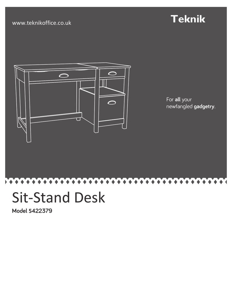
Teknik 5422379 User manual

Teknik

Teknik 5422379 User manual

Teknik Chunky 4 Shelf Bookcase 5422095 User manual

Teknik

Teknik Chunky 4 Shelf Bookcase 5422095 User manual

Teknik Boulevard Cafe Series User manual

Teknik

Teknik Boulevard Cafe Series User manual

Teknik Shaker Style 5428225 User manual

Teknik

Teknik Shaker Style 5428225 User manual

Teknik 5418793 User manual

Teknik

Teknik 5418793 User manual

Teknik Craft 5421416 User manual

Teknik

Teknik Craft 5421416 User manual

Teknik Home Study 5426055 User manual

Teknik

Teknik Home Study 5426055 User manual

Teknik 5414142 User manual

Teknik

Teknik 5414142 User manual

Teknik Barrister Home 5418705 User manual

Teknik

Teknik Barrister Home 5418705 User manual

Teknik 5427415 User manual

Teknik

Teknik 5427415 User manual

Teknik 5426463 User manual

Teknik

Teknik 5426463 User manual

Teknik 5418072 User manual

Teknik

Teknik 5418072 User manual

Teknik Hythe 5426437 User manual

Teknik

Teknik Hythe 5426437 User manual

Teknik 5401562 User manual

Teknik

Teknik 5401562 User manual

Teknik City Centre 5427120 User manual

Teknik

Teknik City Centre 5427120 User manual

Teknik Boulevard Cafe 5421950 User manual

Teknik

Teknik Boulevard Cafe 5421950 User manual

Teknik 5424152 User manual

Teknik

Teknik 5424152 User manual

Teknik Office Affiliate 5427468 User manual

Teknik

Teknik Office Affiliate 5427468 User manual

Teknik Barrister Home 5417772 User manual

Teknik

Teknik Barrister Home 5417772 User manual

Teknik Hampstead Park Compact Desk 5420284 User manual

Teknik

Teknik Hampstead Park Compact Desk 5420284 User manual

Teknik 5427412 User manual

Teknik

Teknik 5427412 User manual
Teknik Boulevard Cafe 5420650 User manual

Teknik

Teknik Boulevard Cafe 5420650 User manual

Teknik Avon 5422051 User manual

Teknik

Teknik Avon 5422051 User manual

Teknik Barrister Home L-Shaped Desk 5418270 User manual

Teknik

Teknik Barrister Home L-Shaped Desk 5418270 User manual

Popular Indoor Furnishing manuals by other brands

Crate&Barrel Jenny Lind quick start guide

Crate&Barrel

Crate&Barrel Jenny Lind quick start guide

Whitewood Furniture SV-39 Assembly instructions

Whitewood Furniture

Whitewood Furniture SV-39 Assembly instructions

Lightolier AGL specification

Lightolier

Lightolier AGL specification

Mayline 5 COLUMN CRNR XR BASE Assembly instructions

Mayline

Mayline 5 COLUMN CRNR XR BASE Assembly instructions

Kesseböhmer TOP-MOTION Mounting instruction

Kesseböhmer

Kesseböhmer TOP-MOTION Mounting instruction

KSIX NTstar BXDESK00 Assembly instructions

KSIX

KSIX NTstar BXDESK00 Assembly instructions

Emerald Home Furnishings Bainbridge 1325642 Assembly instructions

Emerald Home Furnishings

Emerald Home Furnishings Bainbridge 1325642 Assembly instructions

BUT MILY CHAIR PP GREY quick start guide

BUT

BUT MILY CHAIR PP GREY quick start guide

Elements KT900DR Assembly instructions

Elements

Elements KT900DR Assembly instructions

Trasman 2286 BO2 Assembly manual

Trasman

Trasman 2286 BO2 Assembly manual

Teamson Fantasy Fields W-3843G manual

Teamson

Teamson Fantasy Fields W-3843G manual

Duluth Forge CT-L-2 owner's manual

Duluth Forge

Duluth Forge CT-L-2 owner's manual

DIVERSIFIED WOODCRAFTS 3020K Assembly instructions

DIVERSIFIED WOODCRAFTS

DIVERSIFIED WOODCRAFTS 3020K Assembly instructions

ATA Etagere T1633x037 manual

ATA

ATA Etagere T1633x037 manual

Epic Office Furniture Ascend Tech Assembly instructions

Epic Office Furniture

Epic Office Furniture Ascend Tech Assembly instructions

Hillsdale Furniture 4149-831 quick start guide

Hillsdale Furniture

Hillsdale Furniture 4149-831 quick start guide

SEI MS9875H0TX Assembly instructions

SEI

SEI MS9875H0TX Assembly instructions

Rauch 59851.0210 Assembly instructions

Rauch

Rauch 59851.0210 Assembly instructions

manuals.online logo
manuals.online logoBrands
  • About & Mission
  • Contact us
  • Privacy Policy
  • Terms and Conditions

Copyright 2025 Manuals.Online. All Rights Reserved.