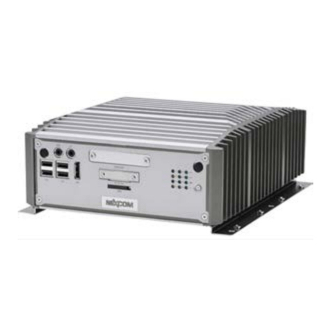
ADITEL KW948 User manual

48 STEP PER DEGREE
RETRANSMISSION UNIT KW948
AMI – GFV MARINE

KW948 48 STEP RETRANSMISSION UNIT KW948
TECHNICAL MANUAL
CONTENTS
1. Contents page
2. Data sheet
3. Installation notes. Checking operation
4. Layout. Schematics are not published in this document
AMI-GFV MARINE LTD
Parham Drive
Eastleigh
Southampton
SO50 4NU
UK
Telephone 44 (0) 2380 480450
Fax 44 (0) 2380 480451
Web www.amimarine.net
Design and manufacture at
ADITEL
Cefn Laboratories
Abergavenny UK
Telephone 44 (0) 1873 840405
Web www.aditel.org.uk www.v-d-r.net
DESIGNER and AUTHOR Andrew Fairgrieve 08/03/06

48 STEP PER DEGREE
RETRANSMISSION UNIT
KW948
INTRODUCTION
The KW948 may be used in a refit when a new
gyro replaces the old one, which had 48 step
per degree repeaters.
This includes certain C Plath, Anschutz, and
other gyros. The repeaters are those that use a
24 volt DC motor supply, with standard
industrial stepper motors having two isolated
windings.
New gyro compasses are normally supplied with
a 24 volt supply so they keep operating if power
is lost. The KW948 uses the same DC source,
so it too can keep operating. If the new gyro
supply does not have enough power it needs an
additional power source.
Typical repeaters take no more than 0.8 amps
per step, but the power required is less than expected from a simple ohms law calculation. The KW948
outputs the full voltage to rotate the repeaters, then, when in position it gives a rectangular pulse train to hold
position at a low current.
SPECIFICATION
INPUT: NMEA 0183. All valid heading sentences. 4800 baud.
One or more decimal places are accepted.
OUTPUT: 6 pin lift-off connector block. 24 volts DC for illumination.
Drive for 2 pole stepper motors, with two separate windings.
Maximum current 6 Amps total, hold current approximately 0.5 amps.
A version for 96 steps per degree is available.
Rotation (follow-up) rate. 5 or 10 degrees per second. Adjustable by jumper.
With an input of two decimal places the motors will naturally rotate in a smoother way than
with one decimal place, 100 steps rather than 10.
ALARM RELAY: Low power single pole change over relay to switch an independent external alarm
POWER: 24 volts DC at 0.2 to 6 Amps depending on load. Resettable fuse.
CONNECTIONS: Pluggable terminal blocks.
ENCLOSURE: 25 cm wide x 35 cm high x 15 cm deep
Grey electrical enclosure with door, for bulkhead mounting.
ENCAPSULATION: Certain parts are normally encapsulated to prevent copying. This means it is not
possible to change the EPROM or replace the output driver chips.
AMI - GFV MARINE Ltd. Southampton, UK
TEL 44 (0) 23 8048 0450 FAX 44 (0) 23 8048 0451/2
Email – [email protected] Web - http://www.amimarine.net

KW948 48 STEP RETRANSMISSION UNIT KW948
INSTALLATION NOTES
CAUTION
If you are not experienced with gyro retransmission do not attempt connecting up to the
repeaters. You are likely to cause damage.
TEST OF THE REPEATER SYSTEM
Check to confirm that all repeater motors are...
• Mechanically free to turn
• Electrically isolated from ground
• The two windings of each motor are identical in resistance
• The two windings of each motor are isolated from each other
• Note the resistance, typically 3 to 20 ohms.
POWER INPUT
The cable must be substantial as large peak currents are drawn. The KW948 is normally
connected to ship’s maintained navigation battery supply.
NMEA 0183 INPUT
The twisted pair cable screen should be grounded at the source, the gyro or its
retransmission unit. Gyro compasses sometimes have a proprietary output, or come set
to the wrong baud rate. If the KW948 does not respond to the gyro’s output then the gyro
is not sending NMEA 0183 heading data.
REPEATERS
The KW948 has one output, to be connected to the existing gyro repeater distribution
box. For first tests do not connect the repeaters. Note that the connectors lift off, BUT
never lift off with power connected!!!
The repeaters have two windings, which connect to S1-S2 and S3-S4.
FIRST TESTS
• LD3 +24v indicator, on
• LD4 status LED
o Off = no power
o Green = processor running OK & heading data input OK
o Flash red/green = processor running OK, data input is not correct
o Red = processor not running. A definite fault
• LD1 data input LED. Flashes in time with the data input
• LD2 diagnostic data output LED. Flashes to show the processor is running
• LD5 & LD6 Red/green step output indicators
o The LEDs come on at switch-on
o If the gyro is turned then the output LEDs LD5 & LD6 will be seen to
change colour and intensity if heading is changed slowly.
o If heading is changed quickly they will appear red & green
o Sometimes it is difficult or unwise to slew the gyro. In that case use a PC
with a simulator program such as AIS-SIM

TESTS WITH THE REPEATERS
Switch on, and measure the output voltages (S1 to S2) and (S3-S4) using a voltmeter.
The voltage should be enough to give about 0.1 to 0.3 amps per winding when the
heading is not moving. More will probably not harm, but it depends on the rating of the
repeater motor,
If this is not the case it will be necessary to change the EPROM.
At rest the two voltage S1-S2 and S3-S4 can be different, and are sometimes zero. Due
to differences in components two KW948s can produce different results, but as long as
they are approximately the same, and the system works, there is no problem.
TESTING THAT REPEATERS FOLLOW
Move heading input. If the repeaters move the wrong way switch off, reverse one pair of
wires, S1-S2. Switch on and try again.
The repeaters will eventually have to be aligned to true heading but for initial tests this is
not necessary.
Move heading and hold it. Check that all the repeaters have followed successfully. Do
the exercise as fast as possible. The KW948 can not go out of synchronisation, and will
follow up if the heading input moves faster than the output rotates.
A good exercise is to use RECSIM simulator and change heading from 000 to 180
degrees. All repeaters should remain in synchronisation.
The output rotation rate can be high or low (10 or 5 degrees per second by default)
according to the setting of jumper J1.

ADJUSTING THE OUTPUT DRIVING POWER
The following paragraphs explain how the KW948 may be adapted to suit different repeaters. To date the
default values have never been changed.
This is now coming to the more technical aspects of the interface. If the repeaters fail to follow on fast turns
then perhaps they need to be driven harder, by forcing more current into the windings, and for longer. This is
made possible by changing some locations in the EPROM. CAUTION. The repeater motors will run hotter
the higher power you use.
SETTING THE EPROM PRESET LOCTIONS
This table is for reference but may easily be used by AMI’s expert dealers to program eproms. If anyone
wants a perfect solution for a particular repeater send it to me and I will do the necessary adjustments.
Location 55 hex 56 hex 57 hex 58 hex
Description PWM pulse width
when stopped
(x 0.25 mS)
PWM width (x
0.25 mS)
Follow up rate per step
(x 0.25 mS)
Step drive width
during turning (x 0.25
mS)
Default or
typical value
2 10 Hex = 16
decimal
10 Hex = 16 decimal 5
What it
means
The holding voltage
and hence current
depends on this
value.
This must be
greater than
location 55.
16 x 0.25 = 4 mS per
step. This gives the 5/10
deg/sec default follow
up rate.
The greater this value
the greater is the
current in the motor
during turns

Table of contents
Other ADITEL Marine Equipment manuals


