6
QUICK START GUIDE
CB-1450 DATA BUOY PLATFORM
2091 Exchange Court
Fairborn, Ohio 45324
937-426-2703
www.NexSens.com
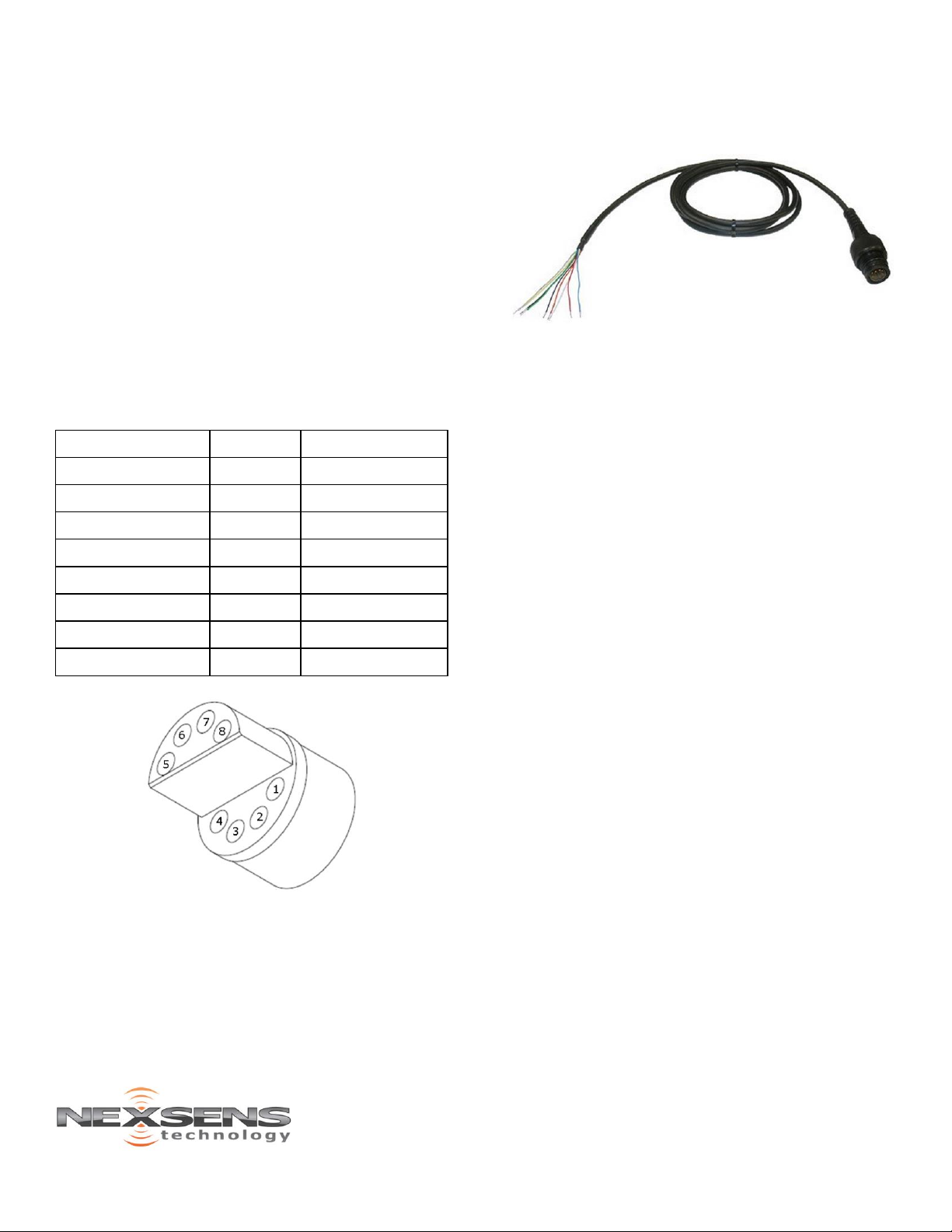
Table 2: Wiring for user-supplied battery/regulator
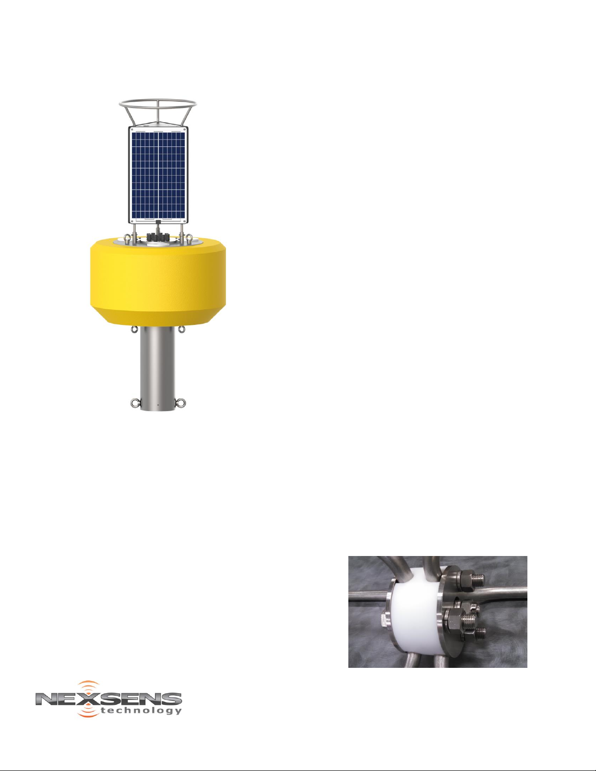
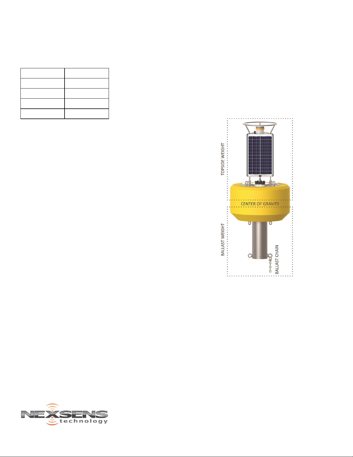
Ballast Weight and Stability
To prevent overturning of a CB-1450 buoy
system and to ensure that it is stable in the
water, sufficient ballast weight must be added.
The required amount is dependent on the wind
and wave conditions. The center of gravity of the
buoy is somewhere near the water surface
without instruments connected. Any weight
added above the water surface must be
appropriately counterbalanced by adding ballast
weight below the surface.
The larger the distance from the location of
added weight to the center of gravity, the greater
the effect on the stability of the buoy will be. For
example, if a weather sensor is mounted 36″
above the water surface, it will cause more
instability than if it were mounted 24″ above the
surface and, as a result, would require more
subsurface ballast weight to counterbalance the
buoy. Conversely, a ballast weight added further
below the surface will provide a greater
stabilizing effect than the same size weight
mounted closer to the surface.
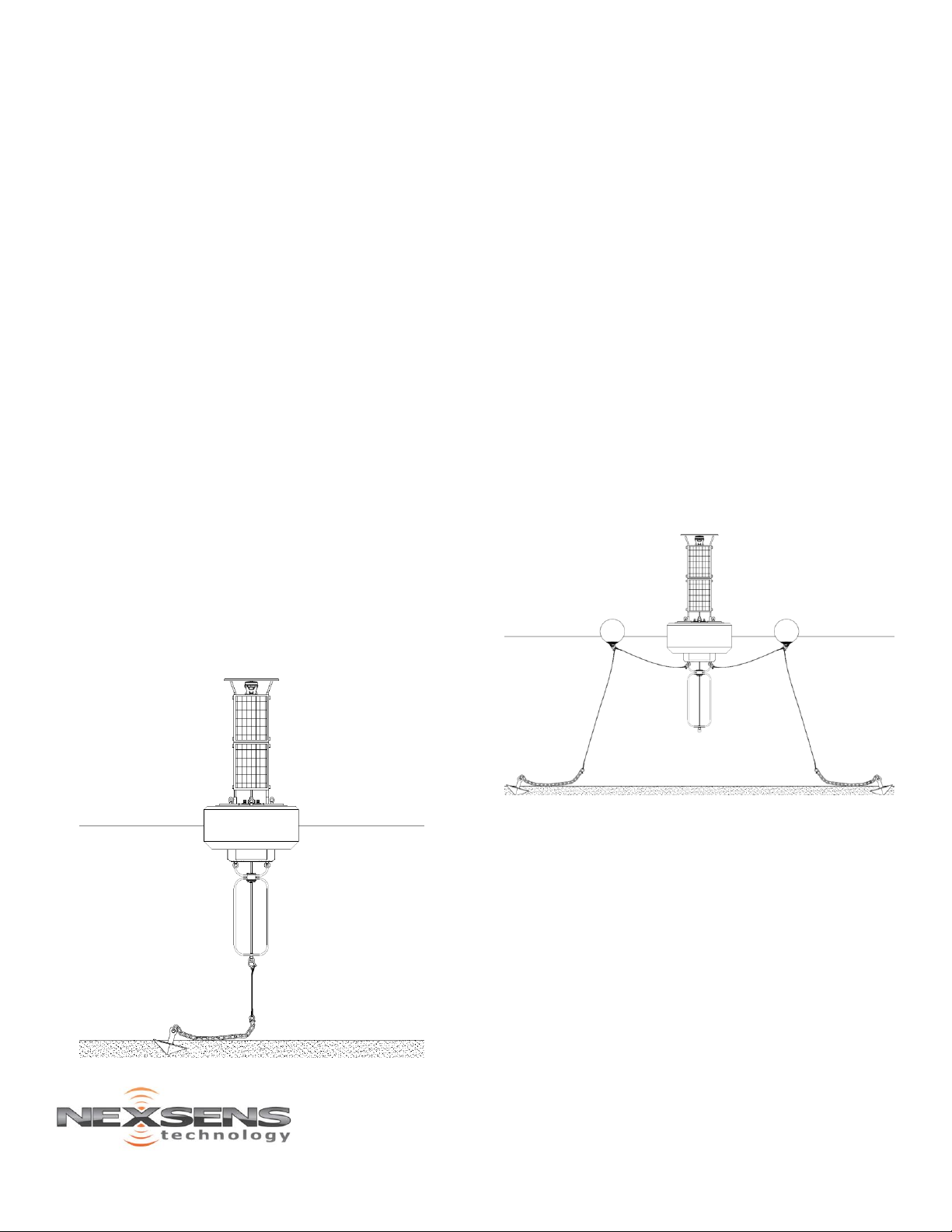
An instrument cage mounted to the buoy frame
helps to stabilize the buoy and provides a deeper
location for mounting additional weight. For
single-point mooring configurations, mooring
chain and lines connected to the bottom of the
cage may provide adequate ballast. For multi-
point configurations, the mooring hardware does
not contribute to the ballast weight.
Before deployment of a CB-1450 system, some
experimentation may be required to properly
balance the buoy. If needed, add ½” chain
(~2.3lb/ft) or other weight to the bottom of the
cage. Figure 13 shows an example of a buoy
system with a short section of chain added.
The buoy data well is not rated for submersion,
so proper ballast weight is critical to ensure that
the buoy does not overturn, including when the
buoy is subjected to additional loading (e.g. high
wind/waves, periodic snow/ice loads, etc.).
Figure 13: CB-1450 Data Buoy with Ballast Chain
Saltwater Deployment
Sacrificial zinc anodes should be used whenever a
buoy is deployed in a saltwater environment to
prevent corrosion. These zinc anodes must be
inspected and replaced as needed.