AXIOMTEK tBOX330-870-FL Series User manual

tBOX330-870-FL Series
Embedded System
User’s Manual

ii
Disclaimers
This manual has been carefully checked and believed to contain accurate information.
Axiomtek Co., Ltd. assumes no responsibility for any infringements of patents or any third
party’s rights, and any liability arising from such use.
Axiomtek does not warrant or assume any legal liability or responsibility for the accuracy,
completeness or usefulness of any information in this document. Axiomtek does not make
any commitment to update the information in this manual.
Axiomtek reserves the right to change or revise this document and/or product at any time
without notice.
No part of this document may be reproduced, stored in a retrieval system, or transmitted, in
any form or by any means, electronic, mechanical, photocopying, recording, or otherwise,
without the prior written permission of Axiomtek Co., Ltd.
Copyright 2014 Axiomtek Co., Ltd.
All Rights Reserved
Dec. 2014, Version A1
Printed in Taiwan

iii
Safety Precautions
Before getting started, please read the following important safety precautions.
1. User should not modify any unmentioned jumper setting without Axiomtek FAE’s
instruction. Any modification without instruction might cause system to become
damage
2. The tBOX330-870-FL does not come equipped with an operating system. An
operating system must be loaded first before installing any software into the
computer.
3. Be sure to ground yourself to prevent static charge when installing the internal
components. Use a grounding wrist strap and place all electronic components in any
static-shielded devices. Most electronic components are sensitive to static electrical
charge.
4. Disconnect the power cord from the tBOX330-870-FL before making any installation.
Be sure both the system and the external devices are turned OFF. Sudden surge of
power could ruin sensitive components. Make sure the tBOX330-870-FL is properly
grounded.
5. Make sure the voltage of the power source is correct before connecting the
equipment to the power outlet.
6. Turn OFF the system power before cleaning. Clean the system using a cloth only.
Do not spray any liquid cleaner directly onto the screen.
7. Do not leave this equipment in an uncontrolled environment where the storage
temperature is below -40℃or above 85℃. It may damage the equipment.
8. Do not open the system’s back cover. If opening the cover for maintenance is a must,
only a trained technician is allowed to do so. Integrated circuits on computer boards
are sensitive to static electricity. To avoid damaging chips from electrostatic
discharge, observe the following precautions:
Before handling a board or integrated circuit, touch an unpainted portion of the
system unit chassis for a few seconds. This will help to discharge any static
electricity on your body.
When handling boards and components, wear a wrist-grounding strap, available
from most electronic component stores.

iv
Classification
1. Degree of production against electric shock: not classified
2. Degree of protection against the ingress of water: IP40
3. Equipment not suitable for use in the presence of a flammable anesthetic mixture
with air or with oxygen or nitrous oxide.
4. Mode of operation: Continuous
General Cleaning Tips
You may need the following precautions before you begin to clean the computer. When you
clean any single part or component for the computer, please read and understand the details
below fully.
When you need to clean the device, please rub it with a piece of dry cloth.
1. Be cautious of the tiny removable components when you use a vacuum cleaner to
absorb the dirt on the floor.
2. Turn the system off before you start to clean up the component or computer.
3. Never drop the components inside the computer or get circuit board damp or wet.
4. Be cautious of all kinds of cleaning solvents or chemicals when you use it for the
sake of cleaning. Some individuals may be allergic to the ingredients.
5. Try not to put any food, drink or cigarette around the computer.

v
Cleaning Tools:
Although many companies have created products to help improve the process of cleaning
your computer and peripherals users can also use household items to clean their computers
and peripherals. Below is a listing of items you may need or want to use while cleaning your
computer or computer peripherals.
Keep in mind that some components in your computer may only be able to be cleaned using
a product designed for cleaning that component, if this is the case it will be mentioned in the
cleaning.
Cloth: A piece of cloth is the best tool to use when rubbing up a component. Although
paper towels or tissues can be used on most hardware as well, we still recommend
you to rub it with a piece of cloth.
Water or rubbing alcohol: You may moisten a piece of cloth a bit with some water or
rubbing alcohol and rub it on the computer. Unknown solvents may be harmful to the
plastics parts.
Vacuum cleaner: Absorb the dust, dirt, hair, cigarette particles, and other particles
out of a computer can be one of the best methods of cleaning a computer. Over time
these items can restrict the airflow in a computer and cause circuitry to corrode.
Cotton swabs: Cotton swaps moistened with rubbing alcohol or water are excellent
tools for wiping hard to reach areas in your keyboard, mouse, and other locations.
Foam swabs: Whenever possible it is better to use lint free swabs such as foam
swabs.
NOTE: We strongly recommended that you should shut down the system before you
start to clean any single components.
Please follow the steps below:
1. Close all application programs
2. Close operating software
3. Turn off power switch
4. Remove all device
5. Pull out power cable

vi
Scrap Computer Recycling
If the computer equipments need the maintenance or are beyond repair, we strongly
recommended that you should inform your Axiomtek distributor as soon as possible for the
suitable solution. For the computers that are no longer useful or no longer working well,
please contact your Axiomtek distributor for recycling and we will make the proper
arrangement.
Trademarks Acknowledgments
Axiomtek is a trademark of Axiomtek Co., Ltd.
Windows® is a trademark of Microsoft Corporation.
AMI® is a registered trademark of American Megatrends Inc.
IBM, PC/AT, PS/2, VGA are trademarks of International Business Machines Corporation.
Intel® and Atom™ are trademarks of Intel Corporation.
Winbond is a trademark of Winbond Electronics Corp.
Other brand names and trademarks are the properties and registered brands of their
respective owners.

vii
Table of Contents
Disclaimers.............................................................................................................. ii
Safety Precautions................................................................................................. iii
Classification......................................................................................................... iv
CHAPTER 1 INTRODUCTION..............................................................................1
1.1 General Description............................................................................ 1
1.2 System Specifications........................................................................ 2
1.2.1 CPU .................................................................................................................... 2
1.2.2 System I/O ......................................................................................................... 2
1.2.3 System Specification........................................................................................ 2
1.2.4 Driver CD Content............................................................................................. 3
1.3 Dimensions ......................................................................................... 4
1.4 I/O Outlets............................................................................................ 5
1.5 Packing List......................................................................................... 6
CHAPTER 2 HARDWARE INSTALLATION......................................................7
2.1 Installing the swappable HDD/SSD or CFast™Card ......................... 7
2.2 Installing the Express Mini Card........................................................ 8
CHAPTER 3 CONNECTOR.....................................................................................9
3.1 Connectors.......................................................................................... 9
3.1.1 VGA & DVI Connector ...................................................................................... 9
3.1.2 Serial Port Connector..................................................................................... 10
3.1.3 USB3.0 Stack Ports ........................................................................................ 10
3.1.4 LED Indicators................................................................................................. 11
3.1.5 DC Power Input connector............................................................................. 11
3.1.6 LAN Connector (LAN1~ LAN4)...................................................................... 11
3.1.7 Digital I/O Connector...................................................................................... 12
3.1.8 SIM Card Connector ....................................................................................... 12
3.1.9 PCI-Express Mini Card Connector................................................................ 13
3.1.10 CFast™Socket................................................................................................. 14
3.1.11 Antenna opening ............................................................................................ 14
3.1.12 USB2.0 Stack ports......................................................................................... 15
3.1.13 CANBus Connector ........................................................................................ 15
3.1.14 HDD tray locker............................................................................................... 15
3.1.15 Remote switch Connector ............................................................................. 16
CHAPTER 4 AMI BIOS SETUP UTILITY ..........................................................17
4.1 Starting.............................................................................................. 17
4.2 Navigation Keys................................................................................ 18
4.3 Main Menu ......................................................................................... 19
4.4 Advanced Menu ................................................................................ 20
4.5 Chipset Menu .................................................................................... 27
4.6 Boot Menu ......................................................................................... 30
4.7 Security Menu ................................................................................... 31
4.8 Save & Exit Menu.............................................................................. 32
APPENDIX A WATCHDOG TIMER...................................................................33
APPENDIX B DIGITAL I/O ..................................................................................35

viii
This page is intentionally left blank.

tBOX330-870-FL Series User’s Manual
Introduction
1
CHAPTER 1
INTRODUCTION
This chapter contains general information and detailed specifications of the tBOX330-870-FL.
The Chapter 1 includes the following sections:
General Description
System Specification
Dimensions
I/O Outlets
Package List
1.1 General Description
The tBOX330-870-FL is an embedded system that supports 3rd Gen. Intel®Core™i7-3517UE
processor (1.7 up to 2.8 GHz) or i3-3217UE processor (1.6 GHz) onboard, to provide
Windows®7 Embedded, Windows®7, Windows®WinCE Embedded and Linux, optimized for
the most endurable operation. It features fanless design with rich I/O, supports onboard 4GB
DDR3 memory, and enhanced system dependability by built-in Watchdog Timer.
Features
3rd Generation Intel®Core™i (17W) processor onboard
Intel®QM77 PCH
High performance DDR3-1600 4GB memory onboard
IEC60945, DNV 2.4 certificate
Fanless with operating temperature range of -40°C ~ +70°C
Isolated RS-232/422/485, CANbus and DIO
Supports USB 3.0 and SATA3
2x removable & lockable 2.5” SATA drive bays and 1x CFast™
3x internal mini PCIe slots and 1x SIM socket
Lockable I/O ports, LAN and USB connectors
Comply to fire protection of vehicles Europe standard PrCEN TS 45545-2
Reliable and Stable Design
The tBOX330-870-FL adopts the advanced cooling system and supporting CFast™,
which makes it especially suitable for vibration environments, the best for industrial
automation, digital signage and gaming application.
Embedded O/S Supported
The tBOX330-870-FL is not only supported Windows®7, but also embedded O/S,
such as Windows®7 Embedded, WinCE and Linux. For storage device, the
tBOX330-870-FL is supported 2x 2.5" SATA drive bays, and 1x CFast™slot.

tBOX330-870-FL Series User’s Manual
Introduction
2
1.2 System Specifications
1.2.1 CPU
CPU
Onboard Intel®Core™i7-3517UE processor (4M Cache, 1.7 up to 2.8 GHz)
Onboard Intel®Core™i3-3217UE processor (3M Cache, 1.6 GHz)
BIOS
American Megatrends Inc. BIOS.
“Load Optimized Default” to backup customized Setting in the BIOS flash chip to
prevent from CMOS battery fail
System Memory
Onboard 4GB DDR3-1600 Memory
Graphics
Integrated Intel®HD Graphics 4000 for DVI, VGA
1.2.2 System I/O
3x 9-pin D-sub male connectors, COM1~3 for isolated RS-232/422/485
1x 9-pin D-sub male connector, isolated CANbus
1x 15-pin D-sub female connector for VGA
1x DVI-D female connector
2x screw audio connectors (Mic-IN/Line-OUT)
4x isolated RJ-45 connectors for 10/100/1000Base-T
2x USB 2.0 connectors(rear side) and 2x USB 3.0 connectors(front side)
1x isolated 4-in/4-out DIO connector
1x 24VDC power input connector
1.2.3 System Specification
Watchdog Timer
Reset supported; 255 levels, 1~255 sec.
Power Supply
24VDC-in power supply
Power Rate:1.8A@24Vdc
Operation Temperature
-40℃~ 70℃(- 40ºF ~ 158ºF)
Storage Temperature
-40℃~ 85℃(- 40ºF ~ 176ºF)
Humidity
5% ~ 95% (non-condensation)
Vibration Endurance
5Grms w/ SSD,CFast (5 ~ 500Hz, X, Y, Z directions)

tBOX330-870-FL Series User’s Manual
Introduction
3
Weight
5.5kg (12.12lb) without package
6.5kg (14.33lb) with package
Dimensions
288.5mm(W) x 211.3mm(D) x 85.75mm(H)
NOTE: All specifications and images are subject to change without notice.
1.2.4 Driver CD Content
Chipset Driver
Graphic Drivers
Audio Drivers
Ethernet Driver
User Manual
Quick Manual
CANBUS Command User Manual
CANBUS Programmer’s Guide
CANBUS Library
AXCAN CANBUS diagnostic tool

tBOX330-870-FL Series User’s Manual
Introduction
4
1.3 Dimensions
The following diagrams show you dimensions and outlines of the tBOX330-870-FL.
tBOX330-870-FL Series User’s Manual
Introduction
5
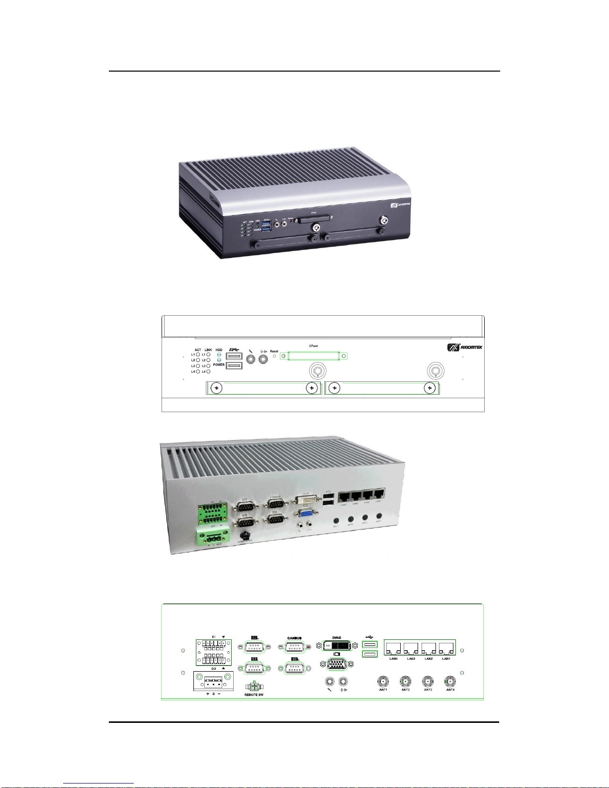
1.4 I/O Outlets
The following figures show you I/O outlets on front view of the tBOX330-870-FL.
Front View
Front View Drawing
Rear View
Rear View Drawing

tBOX330-870-FL Series User’s Manual
Introduction
6
1.5 Packing List
The package bundled with your tBOX330-870-FL should contain the following items:
tBOX330-870-FL System Unit x 1
tBOX330-870-FL Quick Manual x 1
CD x 1 (For Driver and User’s Manual)
Screws pack
Foot pad x4
Wall-mount Brackets
DIO female connector
HDD/SSD (optional)
CFast (optional)
Express Mini Card Module (optional)
If you can not find this package or any items are missing, please contact Axiomtek distributors
immediately.

tBOX330-870-FL Series User’s Manual
Hardware Installation
7
CHAPTER 2
HARDWARE INSTALLATION
The tBOX330-870-FL is convenient for your various hardware configurations, such as HDD
(Hard Disk Drive), CFast™card and mini PCIe card. The chapter 2 will show you how to install
the hardware.
2.1 Installing the swappable HDD/SSD or CFast™Card
Step 1 Turn off the system, and unplug the power cord. Locate thumb screw at the
front side, unlock and loosen screws.
Step 2 Assemble the HDD/SSD bracket together with the SATA HDD/SSD
Step 3 Slide CFast card or HDD/SSD into slot cautiously
Step 4 Fasten screws of HDD/CFast bracket

tBOX330-870-FL Series User’s Manual
Hardware Installation
8
2.2 Installing the Express Mini Card
Step 1 Turn off the system, and unplug the power cord.
Step 2 Turn the system upside down to locate screws at the bottom, loosen screws
to remove the bottom cover.
one slot contains an internal SIM card slot which can support
2G/3G/4G modules.
Step 3 Slide SIM or Mini card into slot cautiously.
Step 4 Fasten the screws.
Step 5 Close the cover on the chassis, and fasten all screws.

tBOX330-870-FL Series User’s Manual
Jumper Setting & Connector
9
CHAPTER 3
CONNECTOR
3.1 Connectors
Connectors are connected the CPU board with other parts of the system. Loose or improper
connection might cause problems. Make sure all connectors are properly and firmly
connected before your turn on the system.
3.1.1 VGA & DVI Connector
DB15 connector commonly is used for the CRT Monitor.
Pin
Signal
Pin
Signal
Pin
Signal
1
Red
2
Green
3
Blue
4
N.C.
5
GND
6
GND
7
GND
8
GND
9
VCC
10
GND
11
N.C.
12
DDC DATA
13
Horizontal Sync
14
Vertical Sync
15
DDC CLK
DVI-D connector is for the digital visual interface display.
Pin
Signal
Pin
Signal
1
TX2-
2
TX2+
3
Ground
4
No use
5
No use
6
DVI_SPD_CLK
7
DVI_SPD DATA
8
No use
9
TX1-
10
TX1+
11
Ground
12
No use
13
No use
14
VGAVCC
15
Ground
16
FPDETECT
17
TX0-
18
TX0+
19
Ground
20
NO use
21
No use
22
Ground
23
TXC+
24
TXC-
CN19B

tBOX330-870-FL Series User’s Manual
Jumper Setting & Connector
10
3.1.2 Serial Port Connector
The COM1~COM3 port connector is a standard DB-9 connector.The pin assignment of RS-
232/RS-422/RS-485 is listed on the following table. If you need COM port to support RS-422
or RS-485, please set it up in BIOS settings.
Pin
RS-232
RS-422
RS-485
1
DCD, Data carrier detect
TX-
Data-
2
RXD, Receive data
TX+
Data+
3
TXD, Transmit data
RX+
NC
4
DTR, Data terminal ready
RX-
NC
5
GND, ground
GND, ground
GND, ground
6
DSR, Data set ready
NC
NC
7
RTS, Request to send
NC
NC
8
CTS, Clear to send
NC
NC
9
RI, Ring indicator
NC
NC
COM
3.1.3 USB3.0 Stack Ports
Pin
Signal USB Port 0
Pin
Signal USB Port 1
1
USB_VCC (+5V level
standby power)
10
USB_VCC (+5V level
standby power)
2
USB_Data2-
11
USB_Data3-
3
USB_Data2+
12
USB_Data3+
4
GND
13
GND
5
SSRX2-
14
SSRX3-
6
SSRX2+
15
SSRX3+
7
GND
16
GND
8
SSTX2-
17
SSTX3-
9
SSTX2+
18
SSTX3+

tBOX330-870-FL Series User’s Manual
Jumper Setting & Connector
11
3.1.4 LED Indicators
Status\LED
ACT( L1~L4)
LINK(L1~L4)
HDD
POWER
LAN Linked
Bright
100Mbps
Green LED
1000Mbps
Yellow LED
HDD Active
Flash
Power on
Bright
3.1.5 DC Power Input connector
There are three pins of the DC-in connector as below table
Pin
Description
Definination
1
+
For DC power in V+.
2
G
For ACC (Ignition)
3
-
For DC power in V-.
3.1.6 LAN Connector (LAN1~ LAN4)
The RJ-45 LAN connectors which support 10/100/1000Mbps
Pin
Description
LAN
1
MDI0+
2
MDI0-
3
MDI1+
4
MDI2+
5
MDI2-
6
MDI1-
7
MDI3+
8
MDI3-

tBOX330-870-FL Series User’s Manual
Jumper Setting & Connector
12
3.1.7 Digital I/O Connector
The tBOX330-870-FL is supported an isolated 4-in/4-out Digital I/O (DIO)
Pin
Signal
Pin
Signal
1
EXT POWER
7
COM+
2
IN0
8
OUT0
3
IN1
9
OUT1
4
IN2
10
OUT2
5
IN3
11
OUT3
6
GND
12
COM-
NOTE: Please refer to Appendix B for more information about Digital I/O
3.1.8 SIM Card Connector
The SIM Card slot is an ISO 7816 standard 6-pin connector for PCI Express Mini
Card.
Pin
Signal
LOCK
OPEN
C1
C2
C3
C5
C6
C7
C1
SIM_PWR
C2
SIM_RESET
C3
SIM_CLK
C5
GND
C6
SIM_VPP
C7
SIM_DATA
Other manuals for tBOX330-870-FL Series
1
Table of contents


