Mark 7 650 User manual

MARK 7® RELOADING USER MANUAL VERSION 2.7 COPYRIGHT 2017
ALL RIGHTS RESERVED
1
Mark 7® 650 X & PRO Autodrive
User Manual
V 2.7
Read this manual and the Dillon Precision Manual completely. Understand all
safety and operating instructions. Failure to comply with the warnings and
instructions may result in serious injury, illness or death.

MARK 7® RELOADING USER MANUAL VERSION 2.7 COPYRIGHT 2017
ALL RIGHTS RESERVED
2
Table of Contents
Table of Contents........................................................................................................................2
Important Safety Instructions.....................................................................................................3
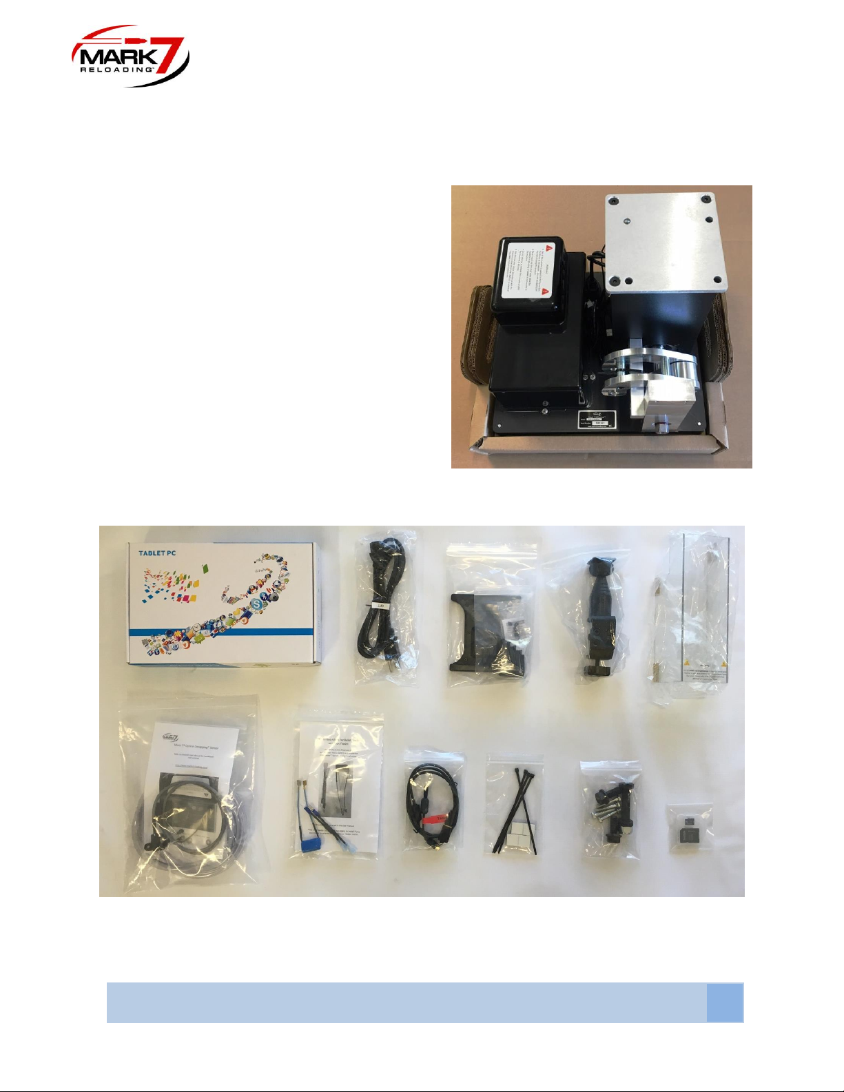
Box Contents...............................................................................................................................6
Set-Up Procedures......................................................................................................................7
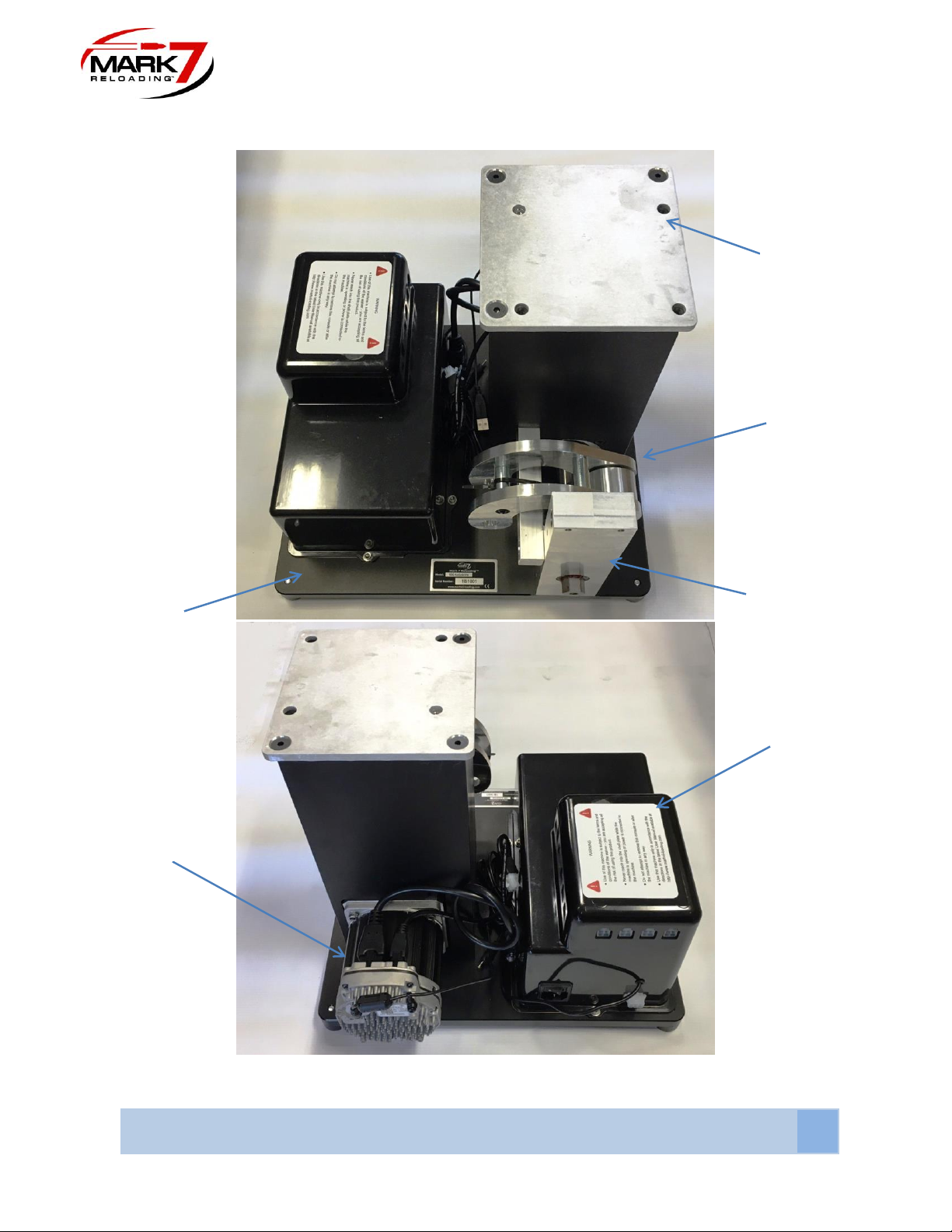
1. Removal Of Equipment From The Packing Carton...............................................................8
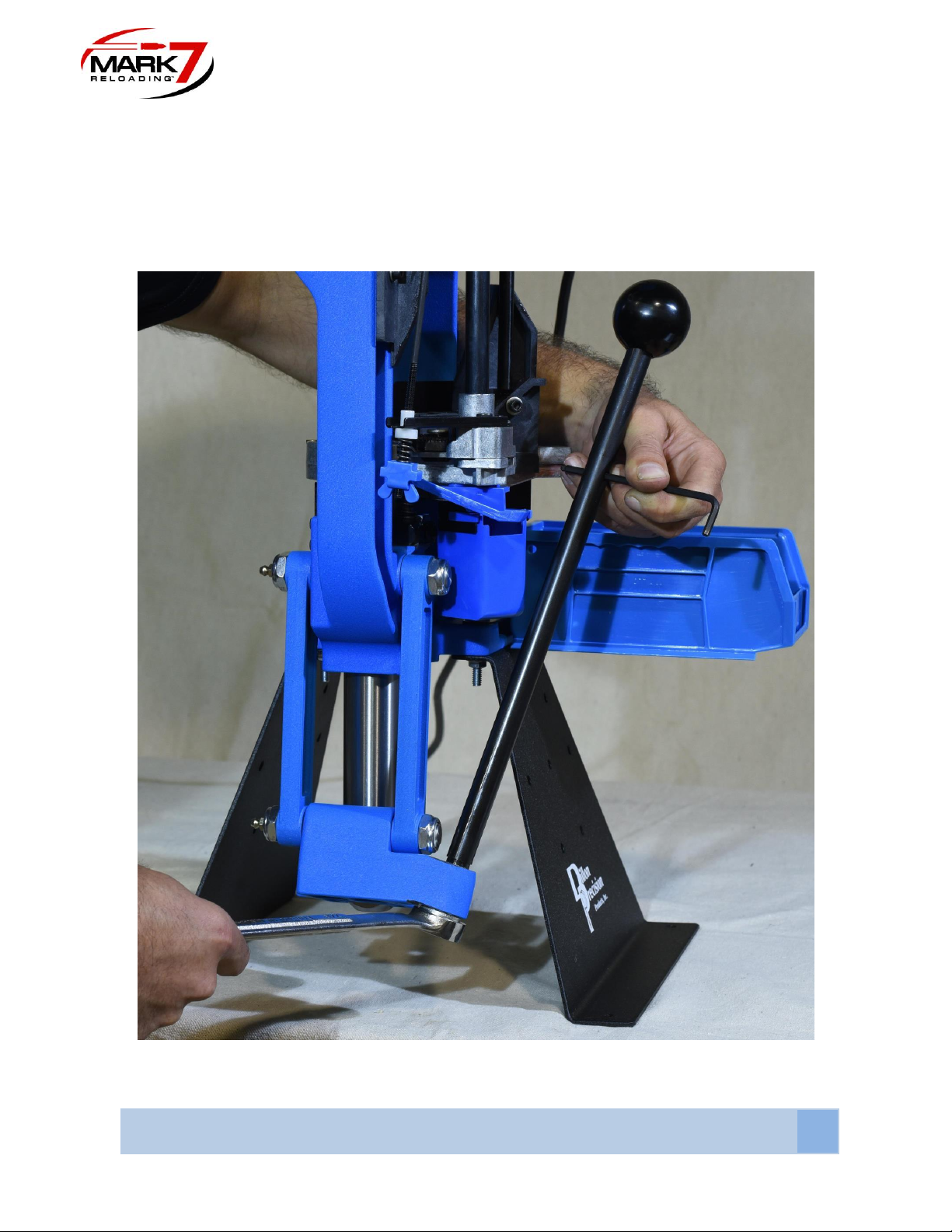
2. Removing 650 Handle...........................................................................................................9
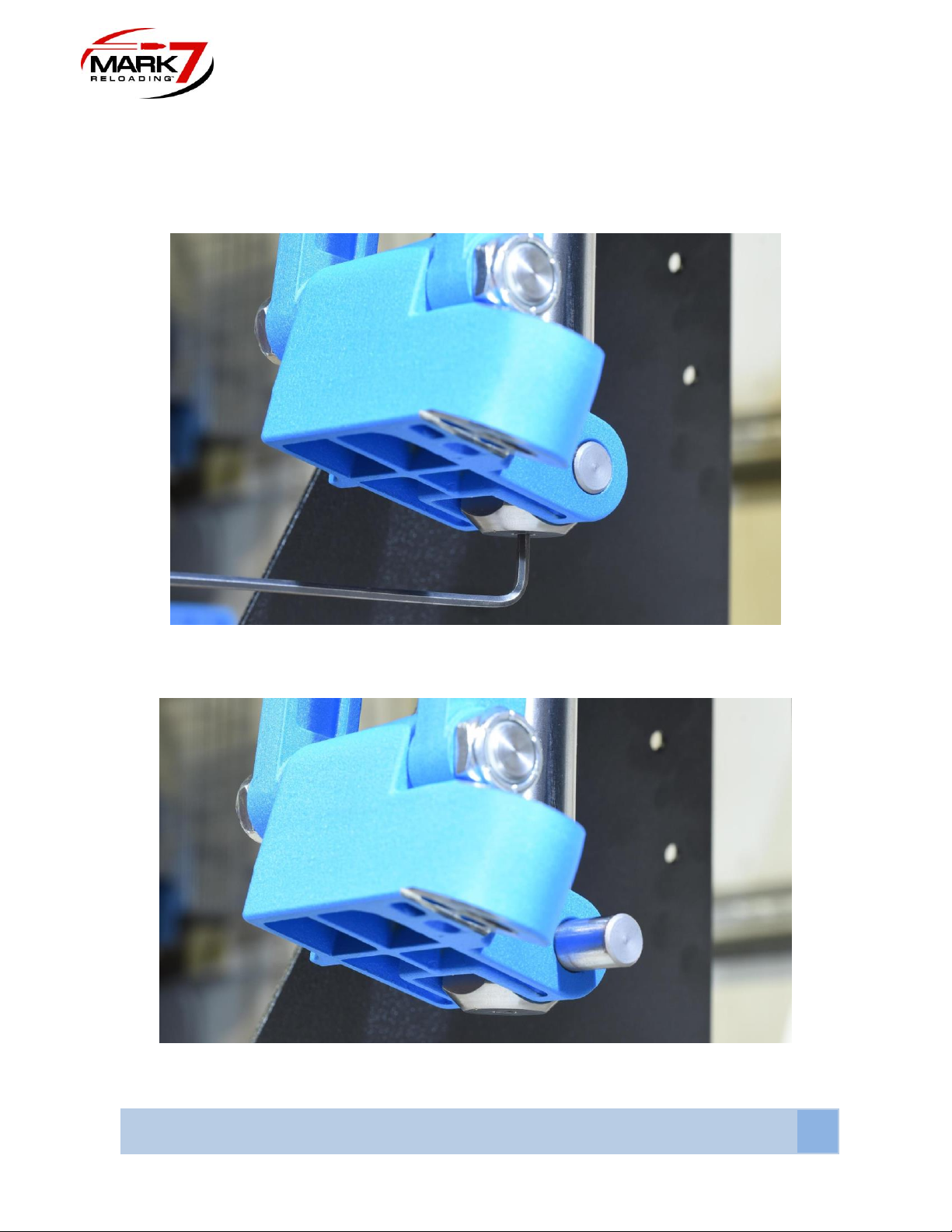
3. Removing 650 Knuckle and Pin ..........................................................................................10
4. Removing 650 Link Arms ....................................................................................................11
5. Removing Link Arm Bottom Pin ..........................................................................................12
6. Reinstalling the 650 Link Arms............................................................................................13
7. Connecting the Mark 7Crank To The 650 Ram...............................................................14
8. Mounting 650.......................................................................................................................15
9. Installing Crank Shield.........................................................................................................18
10. Tablet and Holder Installation............................................................................................19
11. Console Cable Locations and Setup.................................................................................22
12. Manually Driving Press .....................................................................................................25
13. EMI Filter For BulletFeeders .............................................................................................26
14. EMI Filter for Case Feeder ...............................................................................................27
Sensors
Optical Decapping Sensor™ ...................................................................................................29
(Optional)..........................................................................................32
(Optional) ………………..………………………....…………...…….…33
Operating Instructions .............................................................................................................44
Main Screen............................................................................................................................44
Waiver Screen & Software/Firmware version ........................................................................45
Before each session of use of the machine ............................................................................45
Control Screen ........................................................................................................................46
Monitors Screen......................................................................................................................47
Sensors Screen……………………………………………………………………………………….48
Setup Screen...........................................................................................................................49
Software and Firmware Update ..............................................................................................51
General Maintenance and Storage..........................................................................................54

MARK 7® RELOADING USER MANUAL VERSION 2.7 COPYRIGHT 2017
ALL RIGHTS RESERVED
3
Reloading Manual .....................................................................................................................55
Ensuring proper system operation ..........................................................................................55
Calibration...............................................................................................................................55
Test Rounds............................................................................................................................55
Digital Clutch Setting...............................................................................................................56
.........................................................................................................................56
Settings ...................................................................................................................................57
Communications Errors...........................................................................................................58
Troubleshooting........................................................................................................................58
Important Safety Instructions
Read this manual completely prior to installation and operation. Understand all safety and
operating instructions. Failure to comply with the WARNINGS and instructions may result in
serious injury or death. WARNINGS throughout this manual will be symbolized by the yellow
WARNING symbols seen below.
WARNING –Activities using the Mark 7® 650 Autodrive are inherently dangerous and
may lead to injury and even death. Actions as a result of using the Mark 7® product are
solely the responsibility of the user –if you get injured through the reloading process or
through the use of ammunition as a result of the reloading process it is your fault.
WARNING –Mark 7® equipment should only be operated by trained personnel that follow
all safety precautions. Failure to do so could result in serious injury or death.
This product is designed to be used by reloading personnel in conjunction only with a
fully functioning and well lubricated Dillon 650 reloading press. Its use should be limited
to experienced personnel only. All personnel using this equipment are assumed to have
prior experience setting up and operating a Dillon 650 reloading press. This document
contains basic operating and maintenance instructions only.

MARK 7® RELOADING USER MANUAL VERSION 2.7 COPYRIGHT 2017
ALL RIGHTS RESERVED
4
WARNING - Never leave your Mark 7® Autodrive unattended while it is operating.
WARNING –Never run the Mark 7® Autodrive without the crank shield fully attached.
WARNING –Never operate the Mark 7® Autodrive if it is out of factory specification.
WARNING –Never operate the Mark 7® Autodrive unless it is completely within Dillon
Precision factory specifications and is operating within factory parameters. This
includes the shell plate locating pins and other machine-specific features. Read and
understand the latest Dillon Precision 650 manual for your make and model machine and
ensure that you fully understand the Dillon directions.
WARNING –Never operate the Mark 7® Autodrive with any third party accessories that
substantially change the operation of the Mark 7® Autodrive
WARNING –Never operate the Mark 7® Autodrive while impaired.

MARK 7® RELOADING USER MANUAL VERSION 2.7 COPYRIGHT 2017
ALL RIGHTS RESERVED
5
WARNING –Never operate that Mark 7® Autodrive without using high quality brass and
always use sufficient lubrication on your brass while operating the Mark 7® Autodrive.
WARNING –the Mark 7® Autodrive is designed to help automate the process of loading
and processing of ammunition. Never operate the Mark 7® Autodrive at speeds higher
than you have tested and are comfortable with for the type of reloading or processing
that you are undertaking. Run the Mark 7® Autodrive at the slowest possible setting to
create quality ammunition.
WARNING –Always wear protective clothing and eyewear. Flying debris may result when
using this equipment. It is the responsibility of the user to ensure that appropriate
protective clothing and equipment are used to provide protection from those hazards to
which personnel are exposed or could be exposed while working with this product.
Failure to do so could result in serious injury or death.

MARK 7® RELOADING USER MANUAL VERSION 2.7 COPYRIGHT 2017
ALL RIGHTS RESERVED
6
Box Contents
Please review these contents and inform us right away if you appear to be missing any of
these items:
Main: Mark 7® 650 AutoDrive Assembly (1 item)
Middle Insert: (11 items)
•Tablet
•AC Power Cable
•Tablet Holder Mount
•Tablet Holder Clamp
•Crank Shield
•Optical Decapping Sensor™
•EMI Filter Kit for Bullet and Case Feeder
•Micro-USB Cable for Tablet
•Cable Management Zip Ties
•Mounting Hardware and Knuckle
•MicroSD Card: for software updates
Figure 2: Box Contents Included with Machine
Figure 1: 650 Main Assembly

MARK 7® RELOADING USER MANUAL VERSION 2.7 COPYRIGHT 2017
ALL RIGHTS RESERVED
7
Set-Up Procedures
The Mark 7® 650 Autodrive is manufactured with superior craftsmanship, quality
materials and is backed by a factory warranty.
WARNING –Only use Mark 7® accessories with the Mark 7® Autodrive. Mark 7®
equipment is prepared and tested by Mark 7® prior to delivery. To place the equipment
into service, please review the following instructions carefully. In order to ensure proper
operation and avoid damage to your press perform the pre-installation steps.
Prior to installation perform the following manual press checks and adjustments (see
Dillon Precision XL 650 Manual for location of some of the items below):
1. Ensure that the press/autodrive combination is on a very solid surface that does not
move. The Mark 7®autodrive is designed to sit on the 4 rubber feet in the corners, but it
can also be directly bolted to your work bench by removing the 4X rubber feet in the
corners. Use ¼-20 bolts to fasten the baseplate to the work surface from underneath.
Small vibrations can have an unpredictable impact on the operation of the machine.
Ensure that the machine does not move whatsoever when operating.
2. Always have your loader properly grounded to a high-quality grounding line.
3. Ensure that the press operates according to Dillon Precision specifications before you
install the autodrive. Any modifications to your machine outside of the Dillon
standard configuration and parameters will void the Mark 7® warranty. Ensure that
the shell plate retaining shoulder bolt is adjusted so that the shell plate turns freely but is
not too loose. Ensure that the index ring pawl enables the shell plate to move
completely from one index position to the next. Verify that the 650 shell plate is aligned
with the tool head using the 650 alignment pin.
4. Check that there is no powder or other debris under the shell plate. Lubricate the press
as described in the Dillon Precision user's manual. Keep the shell plate clean.
5. There will likely be three (3) cables coming from the machine: the power to the case
feeder, bullet feeder, and autodrive. For best performance we recommend to keep
the case feeder and Mr.Bulletfeeder cables separated from our system cables if
possible.

MARK 7® RELOADING USER MANUAL VERSION 2.7 COPYRIGHT 2017
ALL RIGHTS RESERVED
8
1. 650 Autodrive Component Identification
Figure 3: 650 Base Unit Front and Rear View
Riser Mount
Crank
Base Plate
Servo Motor
Electronics
Console
Front Support

MARK 7® RELOADING USER MANUAL VERSION 2.7 COPYRIGHT 2017
ALL RIGHTS RESERVED
9
2. Removing 650 handle
Using a 7/8”wrench and a pin to lock the rotation of the handle remove the lock nut on the
bottom of the handle as shown below. Depending on the age of the 650 press it may be
required to punch out the handle out of the 650 knuckle.
Figure 4: Removing 650 Handle

MARK 7® RELOADING USER MANUAL VERSION 2.7 COPYRIGHT 2017
ALL RIGHTS RESERVED
10
3. Removing 650 Knuckle and pin
Using a 1/8” allen key remove the set screw on the bottom of the 650 ram and slide out the
knuckle pin. This pin and set screw will be re-used later in the assembly, set aside in a safe
place.
Figure 5: Removing Set Screw from 650 Ram (Do Not Discard Set Screw)
Figure 6: Removing Knuckle Pin (Do not Discard Pin)

MARK 7® RELOADING USER MANUAL VERSION 2.7 COPYRIGHT 2017
ALL RIGHTS RESERVED
11
4. Removing Link Arms From 650 - Using 2X 7/8” or (22mm) wrenches remove the nuts on
the right light link arm. Slide off the right link arm, then pull out the left link arm attached with the
pins as an assembly as shown in the figure below.
Figure 7: Removing Link Arms (Remove Left Link Arm)
Figure 8: Link Arms, Knuckle and Pin Removed From 650.

MARK 7® RELOADING USER MANUAL VERSION 2.7 COPYRIGHT 2017
ALL RIGHTS RESERVED
12
5. Removing The Bottom Pin From The Left Side Link
Place the lower pin in a bench vice or vice grips. If possible wrap the pin in a thick cloth or
rubber sheet to avoid imperfections due to clamping. Remove the lock nut and slide the left link
arm off the pin.
Figure 9: Removing Lower Pin on Left Side Link Arm
Figure 10: Left Link Removed

MARK 7® RELOADING USER MANUAL VERSION 2.7 COPYRIGHT 2017
ALL RIGHTS RESERVED
13
6. Reinstalling The Link Arms To The 650
Slide the upper pin in the left side link into the 650 frame. Install the right side link on the pin
and tighten the lock nuts, keep the lock nuts loose so the link arms can still rotate. Final
tightening will occur when the 650 is mounted to the autodrive.
Figure 11: Re-Installing Link Arms to 650 Press (Do Not Fully Tighten at This Stage)

MARK 7® RELOADING USER MANUAL VERSION 2.7 COPYRIGHT 2017
ALL RIGHTS RESERVED
14
7. Connecting Mark 7® Crank To 650 Ram
Clean the Dillon knuckle pin with alcohol and coat the surface with fresh synthetic multi-purpose
grease. Add grease to the contact points on the Mark 7® knuckle and insert the pin through the
crank and knuckle and lock in place with the set screw.
Figure 12: Installing Mark 7®Knuckle to Crank.
There are 2X set screws on the lower crank that lock it to drive shaft. Due to variations in the
650 press these may need to be backed out in order to line up the 650 ram to the Mark 7®
knuckle properly.
Figure 13: Set Screws on Lower Crank

MARK 7® RELOADING USER MANUAL VERSION 2.7 COPYRIGHT 2017
ALL RIGHTS RESERVED
15
8. Mounting 650 Onto Mark 7® Autodrive - Place the XL 650 onto the top plate of the mount
on the autodrive. Using a 7/16”wrench partially tighten the ¼-20 X 1.5” hex head screws.
Rotate the link arms up and away from the front support.
Figure 14: XL 650 Mounted to Mark 7 Mount

MARK 7® RELOADING USER MANUAL VERSION 2.7 COPYRIGHT 2017
ALL RIGHTS RESERVED
16
Insert the M14 Bolt through the Mark 7® knuckle and through the ram. We recommend moving
the shell plate platform to the mid/upper position so the index ring isn’t engaged. Make sure
both washers on the M14 bolt as shown in the figure below. Partially tighten with a pair of 7/8”
(22 mm) wrenches.
Figure 15: Inserting M14 Bolt through 650 Ram (Shown Partially Tightened)
Rotate the link arms back down and thread the ½ -13”X 1.25”hex head as shown below
Figure 16: 1/2“ Hex Head Screws Partially Tightened

MARK 7® RELOADING USER MANUAL VERSION 2.7 COPYRIGHT 2017
ALL RIGHTS RESERVED
17
Now that everything is connected, fully tighten the XL 650 to the riser mount, top and bottom link
arms, and the M14 Screw through 650 ram. If the 4X set screws on the lower crank were
loosened during the install re-tighten with medium Loctite if possible.
Figure 17: XL 650 fully mounted

MARK 7® RELOADING USER MANUAL VERSION 2.7 COPYRIGHT 2017
ALL RIGHTS RESERVED
18
9. Installing Crank Shield
Remove the backing tape on the crank shield and place the shield around the crank on the right
side of the machine. Gently flex the plastic so you can adhere the 3M tape to the backside of
the front support and front side of the riser mount.
Figure 18: Shield Installed (Left). Removing Shield (Right)
Firmly press on the inside of shield to allow the adhesive to achieve a proper bond. To remove
the shield gently pry at each corner with a flat head screw driver to disengage the 3M
tape as shown in the right image below.

MARK 7® RELOADING USER MANUAL VERSION 2.7 COPYRIGHT 2017
ALL RIGHTS RESERVED
19
10. Tablet & holder installation
The tablet holder can be mounted directly to the 650 case feeder pole or remotely next to the
machine. First attach tablet holder arm to the tablet holder. The tablet holder will make a
positive clicking sound when it is seated correctly. Clamp the tablet holder to the desired
location.
Figure 19: Recommended Tablet Mounting Location (Standard 9 Inch Tablet Shown
Above)

MARK 7® RELOADING USER MANUAL VERSION 2.7 COPYRIGHT 2017
ALL RIGHTS RESERVED
20
WARNING –The operator of the press should always stand in front of the machine,
facing the tablet with hands near the tablet to press the STOP button in the event the
press needs to stop. You should visually see the decapping die spent primers and watch
for bullets toppling or powder spilling. The best vantage point for this is standing to the
front left or right side of the machine.
Figure 20: Tablet Holder orientation for 9 inch tablet (left) 10 inch (Right)
Figure 21: Side view of Tablet holder 9 inch (left) 10 inch (Right)
Other manuals for 650
1
This manual suits for next models
2
Table of contents
Other Mark 7 DC Drive manuals
Popular DC Drive manuals by other brands

Allen-Bradley
Allen-Bradley 25-JBAA installation instructions

Aumuller
Aumuller SP Series Assembly instructions

ISANTA
ISANTA Senco Smart Load SHS51XP installation instructions

INVT
INVT Goodrive300-01A Series Operation manual

LOVATO ELECTRIC
LOVATO ELECTRIC VLB Series installation manual

Evco
Evco EVDRIVE06 Series user manual